

Page 1
MNS Microwave Chip Capacitors MA4M Series
p
MA4M Series
MNS Microwave
Chi
Capacitors
Features
•
Excellent Repeatability
(Wafer-to-Wafer and Lot-to-Lot)
•
Small Size
•
Low Loss, High Q
•
Available with Round or Square Bonding Pads
Description
M/A-COM’s MA4M series of MNS (metal-nitride-silicon) silicon chip capacitors is designed specifically for high reliability and
repeatable performance in microwave circuit ap plications . These
capacitors are made using a low press ure chemical vapor depos ition (LPCVD) that results in dense, uniform nitride layers. These
capacitors exhibit higher capacitance per unit area (resulting in
smaller chip size) than similar MOS, MIS and ceramic capacitors.
Evaporated gold contacts are used t o provide an easily bondable
metal pad on the capacitor chip. M/A-COM MNS capacitors have
shown no measurable capacitance change when subjected to the
rated standoff voltage of 150ºC.
The MA4M series of chip capacitors is an excellent choice for use
in hybrid microwave circuits up through Ku-band, where low
loss, high reliability, small size and temperature stability are
prime concerns.
Case Style
350
These chip capacitors are suited for applications requiring DC
blocks, coupling capacitors, bypass capacitors, capacitive loads
and tuning elements in oscillators, multipliers and filters.
Comparison of M/A-COM MNS Capacitors to Ceramic Chip Capacitors
Characteristics Compared MNS Ceramic
Operating Temperature Range -55 to +200°C -55 to +125°C
Temperature Coefficient 180 PPM 1000 PPM
Insertion Loss of a 20 pF Capacitor in a 50 Ω line at 15 GHz
Chip Size
200 pF, 100V 40 x 40 mils 70 x 70 mils
20 pF, 100V 22 x 22 mils 50 x 50 mils
M/A-COM Division of AMP Incorporated ■ North America: Tel. (800) 366-2266, Fax (800) 618-8883 ■ Asia/Pacific: Tel.+85 2 2111 8088, Fax +85 2 2111 8087
■
Europe: Tel. +44 (1344) 869 595, Fax+44 (1344) 300 020
www.macom.com
AMP and Connecting at a Higher Level are trademarks.
Specifications subject to change without notice.
0.1 dB 0.2 dB
V3.00
Page 2
MNS Microwave Chip Capacitors MA4M Series
Specifications
Chip Capacitor s with Round Bonding Pads
Chip Capacitor s with Square Bonding Pads
Model
Number
Capactance
1,2,3,4
(pF)
±
10 %
Maximum
Standoff
Voltage
2,5
Rating
(Volts)
Chip
Style
Nominal
Top
Contact
Diameter
(mils)
MA4M2002 2 200 132 3.5
MA4M2005 5 200 132 6.0
MA4M1010 10 100 132 6.0
MA4M1020 20 100 132 9.0
MA4M2020 20 200 132 11.5
MA4M1030 30 100 132 11.0
MA4M1050 50 100 132 14.0
MA4M1080 80 100 199 18.0
MA4M1100 100 100 199 20.0
MA4M2100 100 200 200 26.0
MA4M1200 200 100 200 28.0
MA4M1250 250 100 200 32.0
MA4M1300 300 100 201 35.0
Maximum
Standoff
Voltage
Rating
(Volts)
2,5
Chip
Style
Model
Number
Capactance
1,2,3,4
(pF)
±
10 %
MA4M3010 10 200 350
MA4M3020 20 200 351
MA4M3030 30 200 352
MA4M3050 50 200 354
MA4M3100 100 50 358
MA4M3150 150 50 359
Notes:
1 5% capacitance tolerance is available on request.
2 Other capacitance and standoff voltage values are av ai la ble o n re ques t.
3 Capacitance is mea s u r ed a t 1 MHz.
4 Temperature coeffic i ent o f capacitance is nominally 180 PPM/°C.
5 Device failure may occur if standoff voltage ratio is exceeded.
MA4M2300 300 200 263 45.0
MA4M1600 600 100 263 48.0
Maximum Ratings
Applied Voltage
Operating Temperature
Storage Temperature
Specified standoff voltage
-55°C to +200°C
-55°C to +200°C
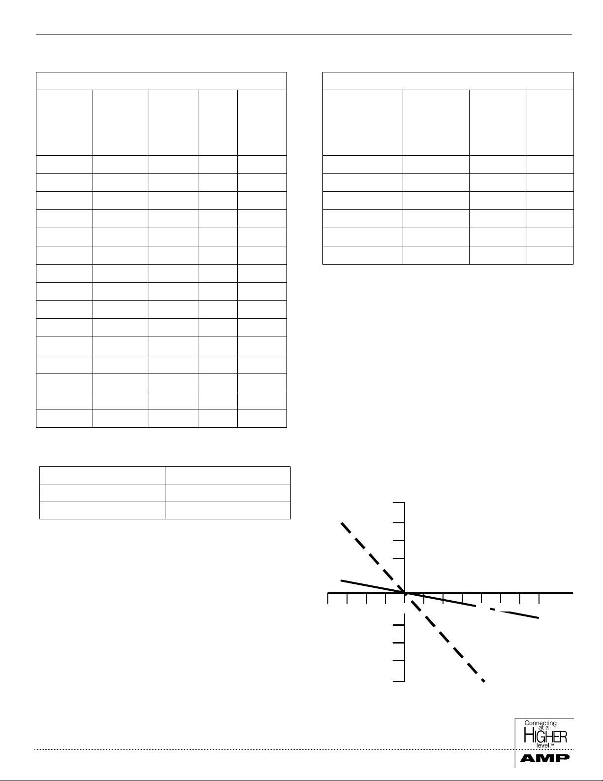
TYPICAL CAPACITANCE CHANGE FOR MNS and
CERAMIC CAPACITOR vs TEMPERATURE
(200 pF CAPACITOR)
+10
%
+8
+6
+4
-75 -25 0 50
25 125 150 200
-4
-6
-8
-10
CAPACITANCE
CHANGE
TEMPERATURE qC
M/A-COM M A4M1200
CAPACITOR
CERAMIC
CAPACITOR
M/A-COM Division of AMP Incorporated ■ North America: Tel. (800) 366-2266, Fax (800) 618-8883 ■ Asia/Pacific: Tel.+85 2 2111 8088, Fax +85 2 2111 8087
■
Europe: Tel. +44 (1344) 869 595, Fax+44 (1344) 300 020
www.macom.com
AMP and Connecting at a Higher Level are trademarks.
Specifications subject to change without notice.
V3.00
Page 3

MNS Microwave Chip Capacitors MA4M Series
Case Style
C A
B
Chip INCHES MILLIMETERS
Style DIM. MIN. MAX. MIN. MAX.
132 A 0.020 0.024 0.51 0.61
B 0.003 0.008 0.08 0.203
199 A 0.027 0.031 0.69 0.79
B 0.004 0.008 0.10 0.203
200 A 0.037 0.041 0.94 1.04
B 0.004 0.008 0.10 0.203
201 A 0.047 0.051 1.19 1.30
B 0.004 0.008 0.10 0.203
263 A — 0.060 — 1.52
B 0.004 0.008 0.10 0.203
Note:
For “C” dimension on above case styles, see spec i f i c a t io ns.
Chip INCHES MILLIMETERS
C A
B
Style DIM. MIN. MAX. MIN. MAX.
350 A 0.018 0.021 0.46 0.53
B — 0.008 — 0.203
C — 0.009 — 0.23
351 A 0.018 0.021 0.46 0.53
B — 0.008 — 0.203
C — 0.012 — 0.30
352 A 0.018 0.021 0.46 0.53
B — 0.008 — 0.203
C — 0.015 — 0.38
354 A 0.020 0.023 0.51 0.58
B — 0.008 — 0.203
C — 0.018 — 0.46
358 A 0.018 0.021 0.46 0.53
B — 0.008 — 0.203
C — 0.013 — 0.33
359 A 0.018 0.021 0.46 0.53
B — 0.008 — 0.203
C — 0.016 — 0.41
M/A-COM Division of AMP Incorporated ■ North America: Tel. (800) 366-2266, Fax (800) 618-8883 ■ Asia/Pacific: Tel.+85 2 2111 8088, Fax +85 2 2111 8087
■
Europe: Tel. +44 (1344) 869 595, Fax+44 (1344) 300 020
www.macom.com
AMP and Connecting at a Higher Level are trademarks.
Specifications subject to change without notice.
V3.00
Page 4

MNS Microwave Chip Capacitors MA4M Series
p
Bonding and Handling Considerations for
MNS Chi
Capacitors
Handling
Normal precautions that are common to the handling of hybrid
semiconductors also apply to MNS chip capacitors. Removal of
chips from waffle packs and subsequent handling should be
done with a vacuum pencil. Pencils equipped with either metallic or nonmetallic tips are acceptable.
Surface Preparation
Each MNS chip and substrate should be free of oils and other
surface contamination. Such contaminants may result in poor
solder wetting. Cleansing can be done with acetone, alcohol,
freon, TMS or other common microelectronic solvents. Burnishing of MNS capacitor chips is not necessary or recommended.
Solder
Soldering temperatures up to 300ºC are acceptable for a duration
not greater than 5 seconds for MNS chip capacitors. Any of the
common tin-lead-silver, lead-indium, or higher temperature gold
alloy solders are acceptable provided that the 300ºC temperature
is not exceeded. Pure tin or tin-antimony solders are not
recommended. Cleaning of residual flux is required and can be
accomplished with a fluorinated or chlorinated solvent.
Conductive Epoxy
Any of the conductive epoxies that are available for semiconductor die attachment are acceptable for MNS chip capacitor
attachment. Follow the manufacturer’s recommendations for
mixing and application carefully. Take care to seat the capacitor
on the substrate using a soft implement.
Lead Bonding
Ball, ultrasonic, TC or pulse bonding of the wire or ribbon leads
are all acceptable methods . Temperature for the pulse bon der
should not exceed 300ºC. Maximum pressure applied to the
MNS capacitor chips should not exceed 25 grams for any of the
methods used. Proper procedure will result in bond strength that
exceeds MIL-STD-883B Method 2011.2 for gold wire or gold
ribbon.
M/A-COM Division of AMP Incorporated ■ North America: Tel. (800) 366-2266, Fax (800) 618-8883 ■ Asia/Pacific: Tel.+85 2 2111 8088, Fax +85 2 2111 8087
■
Europe: Tel. +44 (1344) 869 595, Fax+44 (1344) 300 020
www.macom.com
AMP and Connecting at a Higher Level are trademarks.
Specifications subject to change without notice.
V3.00
 Loading...