

Page 1
Silicon Double Balanced HMIC
Mixer, 1700 - 2300 MHz
TM
V 1.00
MA4EX190L-1225
Features
n Low Cost Miniature Plastic Package
n 6.1 dB Typical Conversion Loss at 1900 MHz
n 6.5 dB Typical Conversion Loss at 2200 MHz
n +3 to +7 dBm LO Drive
n HMIC Patented Process
n Silicon Low Barrier Schottky Diodes
n DC - 500 MHz IF Bandwidth
Description
M/A-COM’s MA4EX190L-1225 is a silicon monolithic
1500-2500 MHz double balanced mixer in a low cost
miniature surface mount SOT-25 package. The die uses
M/A-COM’s unique HMICTM silicon/glass process to
achieve low loss passive elements while retaining the
advantages of high barrier silicon Schottky diodes.
Applications
These mixers are well suited for high volume WLAN and
cellular applications where small size and repeatability are
required. Typical applications include frequency
conversion, modulation, and demodulation for receivers
and transmitters in both portable cellular and base
station applications.
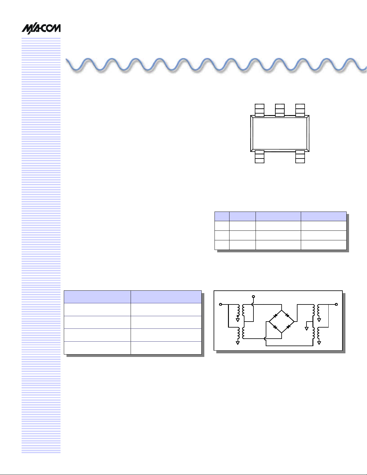
Package Outline
2 3 1
4
5
PIN Configuration
PIN Function PIN Function
1 RF 4 GND
2 GND 5 IF
3 LO
Absolute Maximum Ratings
Parameter Maximum Ratings
Operating Temperature
Storage Temperature
Incident LO Power
Incident RF Power
1. Exceeding these limits may cause permanent damage.
-40 °C to +85 °C
-65 °C to +150 °C
1
+20 dBm
+20 dBm
Functional Schematic
RF
IF
LO
1
Page 2
Silicon Double Balanced HMICTM Mixer, 1700-2300 MHz
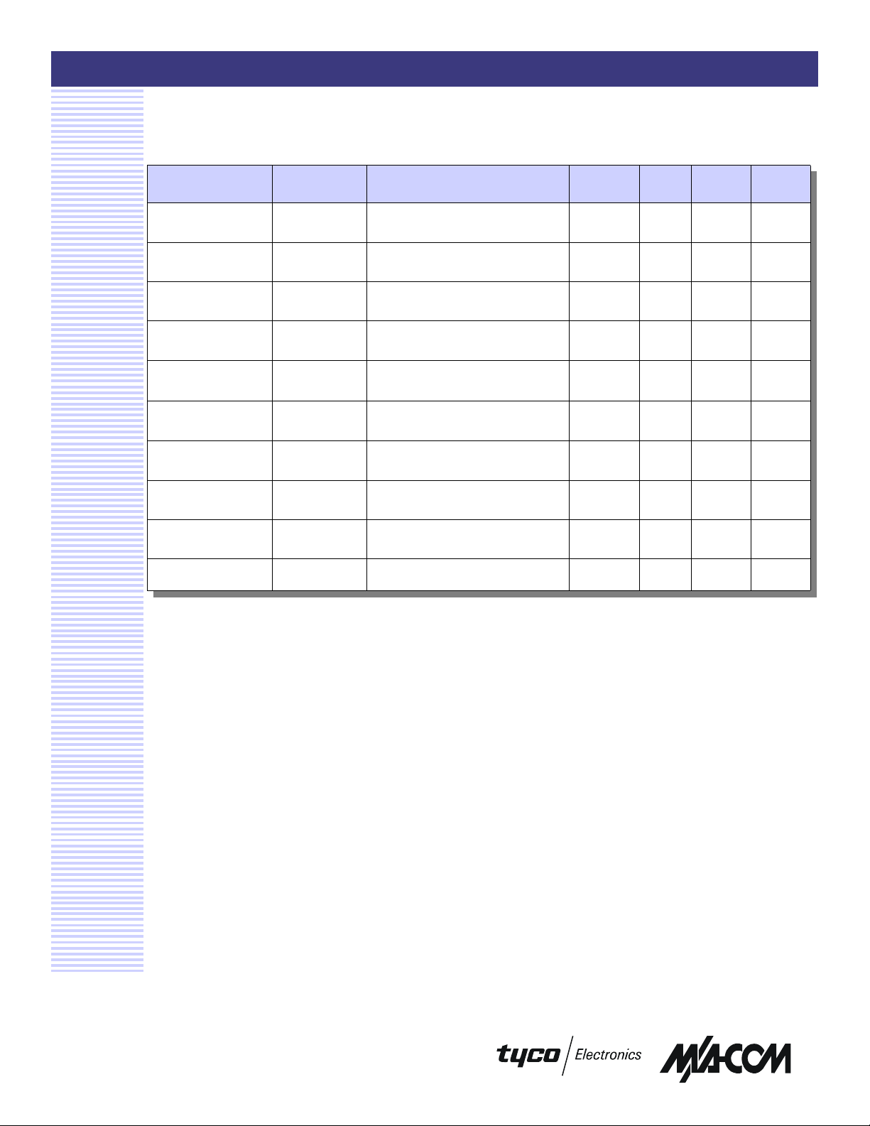
Electrical Specifications: @ + 25 °C
MA4EX190L-1225
V 1.00
Parameter Frequency
Conversion Loss
L - R Isolation
L - I Isolation
R - I Isolation
LO VSWR
RF VSWR
IF VSWR
Input IP3
Input 1 dB Compression
IF 1 dB Bandwidth
1900 MHz
1700-2300 MHz
1900 MHz
1700-2300 MHz
1900 MHz
1700-2300 MHz
1900 MHz
1700-2300 MHz
1900 MHz
1700-2300 MHz
1900 MHz
1700-2300 MHz
DC - 500 MHz LO Drive = +5 dBm
1900 MHz
1700-2300 MHz
1900 MHz
1700-2300 MHz
MHz 0 500.0
Range
Test Conditions Units Min. Typ. Max.
LO Drive = +5 dBm
RF = -10 dBm, IF = 60 MHz
LO Drive = +5 dBm
RF Level = -10 dBm
LO Drive = +5 dBm
RF Level = -10 dBm
LO Drive = +5 dBm
RF Level = -10 dBm
LO Drive = +5 dBm
RF Level = -10 dBm
LO Drive = +5 dBm
RF Level = -10 dBm
RF Level = -10 dBm
LO Drive = +7 dBm
IF = 60 MHz
LO Drive = +7 dBm
IF = 60 MHz
dB
dB
dB
dB
dB
dB
dB
dB
2.0:1
1.15:1
1.5:1
dBm
dBm
dBm
dBm
6.1
25.0
23.0
20.0
14.5
13.5
6.5
24.0
21.0
19.0
2.0:1
1.7:1
+16.5
+17.0
+1.9
+2.5
6.8
8.5
M/A-COM Inc. and its affiliates reserve the right to make changes to the product(s)
or information contained herein without notice. MA-COM makes no warranty,
representation or guarantee regarding the suitability of its products for any
particular purpose, nor does M/A-COM assume any liability whatsoever arising out
of the use or application of any product(s) or information.
Visit www.macom.com for additional data sheets and product information.
n North America: Tel. (800) 366-2266
2
n Asia/Pacific: Tel.+81-44-844-8296, Fax +81-44-844-8298
n Europe: Tel. +44 (1344) 869 595, Fax+44 (1344) 300 020
Page 3

Silicon Double Balanced HMICTM Mixer, 1700-2300 MHz
Typical Performance Curves (LO Drive = +5 dBm, RF = -10 dBm, IF = 60 MHz)
Isolation Conversion Loss
MA4EX190L-1225
V 1.00
5.000
5.500
PLO = 7dBm
6.000
6.500
LOSS (DB)
7.000
7.500
8.000
1700 1750 1800 1850 1900 1950 2000 2050 2100 2150 2200 2250 2300
PLO = 3dBm
FREQUENCY (MHz)
PLO = 5dBm
VSWR
4.00
3.50
3.00
2.50
VSWR
2.00
1.50
L Port
I Port
R Port
0
-5
-10
-15
L-I
ISOLATION(dB)
-20
-25
-30
1700 1750 1800 1850 1900 1950 2000 2050 2100 2150 2200 2250 2300
R-I
L-R
FREQUENCY (MHz)
Input IP3 & 1 dB Compression Point
25
PLO = 7dBm PLO = 5dBm
20
15
10
IP3 (dBm)
5
1db Compression Pt.
PLO = 3dBm
1.00
1700 1750 1800 1850 1900 1950 2000 2050 2100 2150 2200 2250 2300
50 100 150 200 250 300 350 400 450 500
FREQUENCY (MHz)
M/A-COM Inc. and its affiliates reserve the right to make changes to the product(s)
or information contained herein without notice. MA-COM makes no warranty,
representation or guarantee regarding the suitability of its products for any
particular purpose, nor does M/A-COM assume any liability whatsoever arising out
of the use or application of any product(s) or information.
Visit www.macom.com for additional data sheets and product information.
0
1700 1750 1800 1850 1900 1950 2000 2050 2100 2150 2200 2250 2300
FREQUENCY (MHz)
n North America: Tel. (800) 366-2266
3
n Asia/Pacific: Tel.+81-44-844-8296, Fax +81-44-844-8298
n Europe: Tel. +44 (1344) 869 595, Fax+44 (1344) 300 020
Page 4

Silicon Double Balanced HMICTM Mixer, 1700-2300 MHz
MA4EX190L-1225
V 1.00
Case Style - SOT-25
Ordering Information
Part Number Package
MA4EX190L-1225 Tube
SOT-25 Dimensions
Dim
A .106 .122 2.70 3.10
B .100 .118 2.54 3.00
C — .051 — 1.30
D .063 REF. 1.60 REF.
E .032 .043 .80 1.10
F .014 .020 .35 .50
G .003 — .08 —
H .000 .006 .00 .15
J .018 REF. .45 REF.
Notes: 1. Leads Coplanarity should be 0.003 (0.08) max.
Inches
Min. Max. Min. Max.
Millimeters
MA4EX190L-1225T Tape and Reel
M/A-COM Inc. and its affiliates reserve the right to make changes to the product(s)
or information contained herein without notice. MA-COM makes no warranty,
representation or guarantee regarding the suitability of its products for any
particular purpose, nor does M/A-COM assume any liability whatsoever arising out
of the use or application of any product(s) or information.
Visit www.macom.com for additional data sheets and product information.
n North America: Tel. (800) 366-2266
4
n Asia/Pacific: Tel.+81-44-844-8296, Fax +81-44-844-8298
n Europe: Tel. +44 (1344) 869 595, Fax+44 (1344) 300 020
 Loading...