

Page 1
M/A-COM, Inc.
North America: Tel. (800) 366-2266 ■ Asia/Pacific: Tel. +81 (03) 3226-1671 ■ Europe: Tel. +44 (1344) 869 595
Fax (800) 618-8883 Fax +81 (03) 3226-1451 Fax +44 (1344) 300 020
1
Specifications Subject to Change Without Notice.
V3.00
Step Recovery
Diodes
MA43000, MA44600,
MA44700 Series
Features
●
Low Transition Times
●
Tight Capacitance Ranges
●
High Voltage and Low Thermal Resistance
for Higher Input Power
●
Surface Mount Package Available (SOT-23)
Description
The MA44600 series of Step Recovery diodes is designed
for use in low and moderate power multipliers with output frequencies of up to 20 GHz. These Step Recovery
diodes generate harmonics by storing a charge as the
diode is driven to forward conductance by the positive
voltage of the input signal. When the signal reverses
polarity, this charge is extracted. The Step Recovery diode
will appear as a low impedance current source until all the
charge is extracted, then it will “snap” to a higher impedance. This causes a voltage pulse to form in the impulse
circuit of the multiplier. Step Recovery diodes make
excellent high order multipliers such as comb generators.
They are also useful as efficient moderate power X2- X4
multipliers.
Applications
High Order Narrow Band Moderate Power Multipliers
(MA44600 series)
Comb Generators (MA43592, MA43543)
High Power Circuit Tested Multiplier (MA43000 Series)
Surface Mount Low Power Multipliers (MA44700 Series)
Page 2
M/A-COM, Inc.
North America: Tel. (800) 366-2266 ■ Asia/Pacific: Tel. +81 (03) 3226-1671 ■ Europe: Tel. +44 (1344) 869 595
Fax (800) 618-8883 Fax +81 (03) 3226-1451 Fax +44 (1344) 300 020
2
Specifications Subject to Change Without Notice.
V3.00
Step Recovery Diodes MA43000, MA44600, MA44700 Series
Electrical Specifications
@ 25°C
Snap V aractors
Notes:
1. When ordering, specify the desired case style by adding the case designation as a suffix to the model number.Case styles for the MA44600
series are 30, 91 and 93.To order in chip form, add the suffix “134” to
the model number.The nominal chip size for the MA44600 series is
15 mils.
Junction
3
Minimum
2
Capacitance Minimum Transition Time T
S
4
Reverse Range (Cj) Lifetime (ps)
Model
1
V oltage V
R
Min./Max. 10 mA/6 mA
Number (Volts) (pF) TI (ns) Nominal Max.
MA44621A 20 0.2 / 0.3 7 50 100
MA44621B 20 0.3 / 0.4 7 50 100
MA44621C 20 0.4 / 0.5 7 50 100
MA44622A 20 0.5 / 0.7 7 50 100
MA44622B 20 0.7 / 0.9 7 50 100
MA44631A 30 0.3 / 0.5 8 70 100
MA44631B 30 0.5 / 0.7 8 70 100
MA44631C 30 0.7 / 0.9 8 70 100
MA44641A 40 0.4 / 0.6 12 90 150
MA44641B 40 0.6 / 0.8 12 90 150
MA44641C 40 0.8 / 1.1 12 90 150
MA44652A 50 0.5 / 0.7 15 150 200
MA44652B 50 0.7 / 0.9 15 150 200
MA44652C 50 0.9 / 1.1 15 150 200
MA44663A 60 0.7 / 0.9 20 250 300
MA44663B 60 0.9 / 1.1 20 250 300
MA44663C 60 1.1 / 1.5 20 250 300
MA44663D 60 1.5 / 2.0 20 250 300
2.
Reverse
voltage (VR) is measured at a reverse bias current of 10 µA.
3. Junction capacitance is measured at a reverse voltage of 6 volts and a
frequency of 1 MHz.
4. Transition time is measured between 20% and 80% points on the voltage recovery trace.Test conditions are +10 mA and -10 volts.
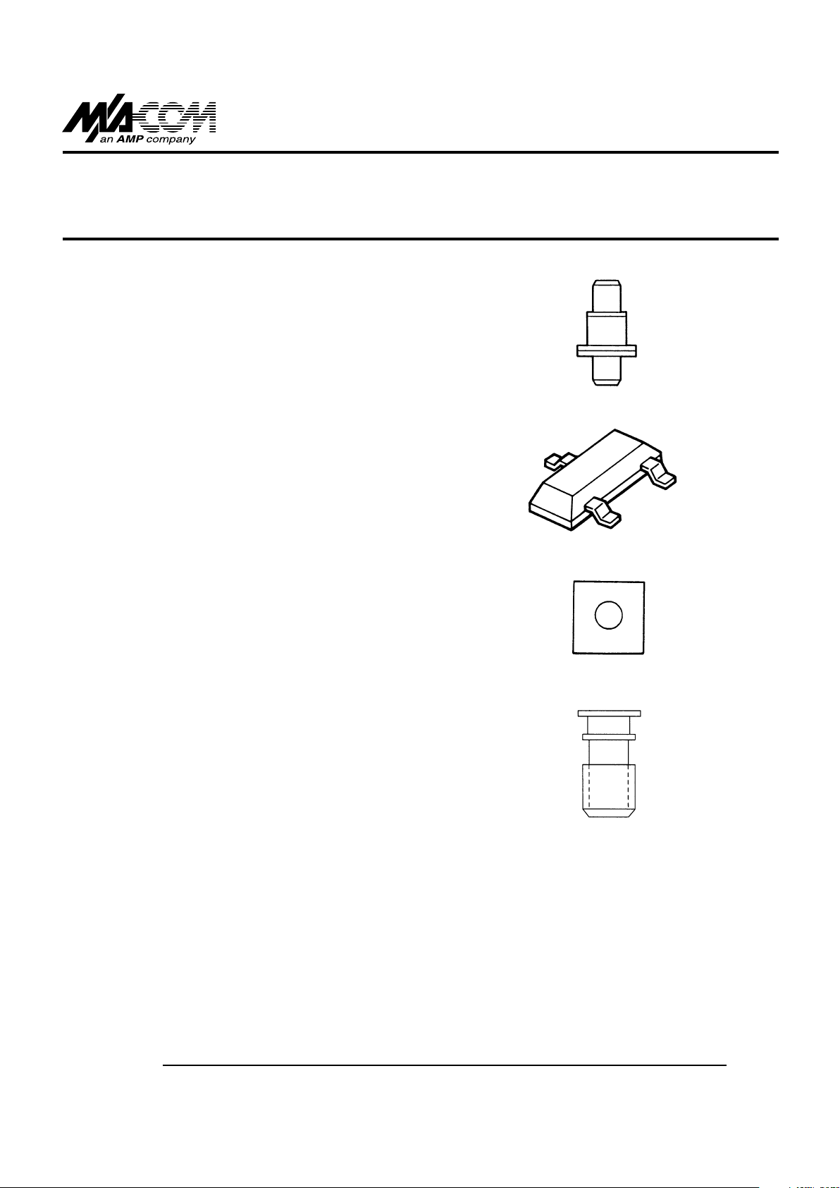
Case Styles (See appendix for complete dimensions)
30
91
93
134
Page 3

M/A-COM, Inc.
North America: Tel. (800) 366-2266 ■ Asia/Pacific: Tel. +81 (03) 3226-1671 ■ Europe: Tel. +44 (1344) 869 595
Fax (800) 618-8883 Fax +81 (03) 3226-1451 Fax +44 (1344) 300 020
3
Specifications Subject to Change Without Notice.
V3.00
Notes:
1. The standard case styles are indicated for each model number.
Other case styles are available.Consult the factory for information.
Step Recovery Diodes MA43000, MA44600, MA44700 Series
Electrical Specifications
@ 25° C (Cont’d)
High Power Circuit Tested Step Recovery Diodes
Min./Max.
2
Minimum Maximum Reverse
Output Input Output Input Voltage
Model Case
1
Power Frequency Frequency Power V
R
Number Style (Watts) (GHz) (GHz) (Watts) (Volts)
MA43000 103 4.0 0.333 2.0 15 85 - 105
MA43002 91 1.5 2.000 6.0 5 45 - 70
MA43004 91 0.3 3.300 13.0 2 30 - 45
Min./Max.
3
Junction Min./Max. Maximum Maximum
Capacitance Lifetime,T
L
Snap Time,T
S
Thermal
Model C
j
10 mA/6 mA -10V/10 mA Resistance, jc
Number (pF) (ns) (ps) (C/W)
MA43000 3 - 4.50 250 - 500 600 12
MA43002 1.60 - 2.40 75 - 225 250 25
MA43004 0.45 - 0.85 20 - 50 150 45
Surface Mount Step Recovery Diodes (SOT-23)
Min./Max. Minimum
Suggested
Total Reverse
Capacitance V oltage V
R
Nominal Maximum Nominal Nominal
(pF) (Volts) Carrier T ransition Input Output
Model
f = 1 MHz
IR= 10µA
Lifetime Time Frequency Frequency
Number
VR= 6 V
TL(ns) TS(psec) (GHz) (GHz)
MA44767 3 - 4.5 250 - 500 600 0.05 - 0.5 0.5 - 1.5
MA44768 1.6 - 2.4 30V 75 - 225 250 0.1 - 1 0.5 - 2.5
MA44769 0.8 -1.2 20 - 50 150 0.1 - 1 1 - 5
2. Reverse voltage is measured at reverse bias current of 10 µA.
3. Junction capacitance is measured at a reverse bias of 6 volts and
a frequency of 1 MHz.
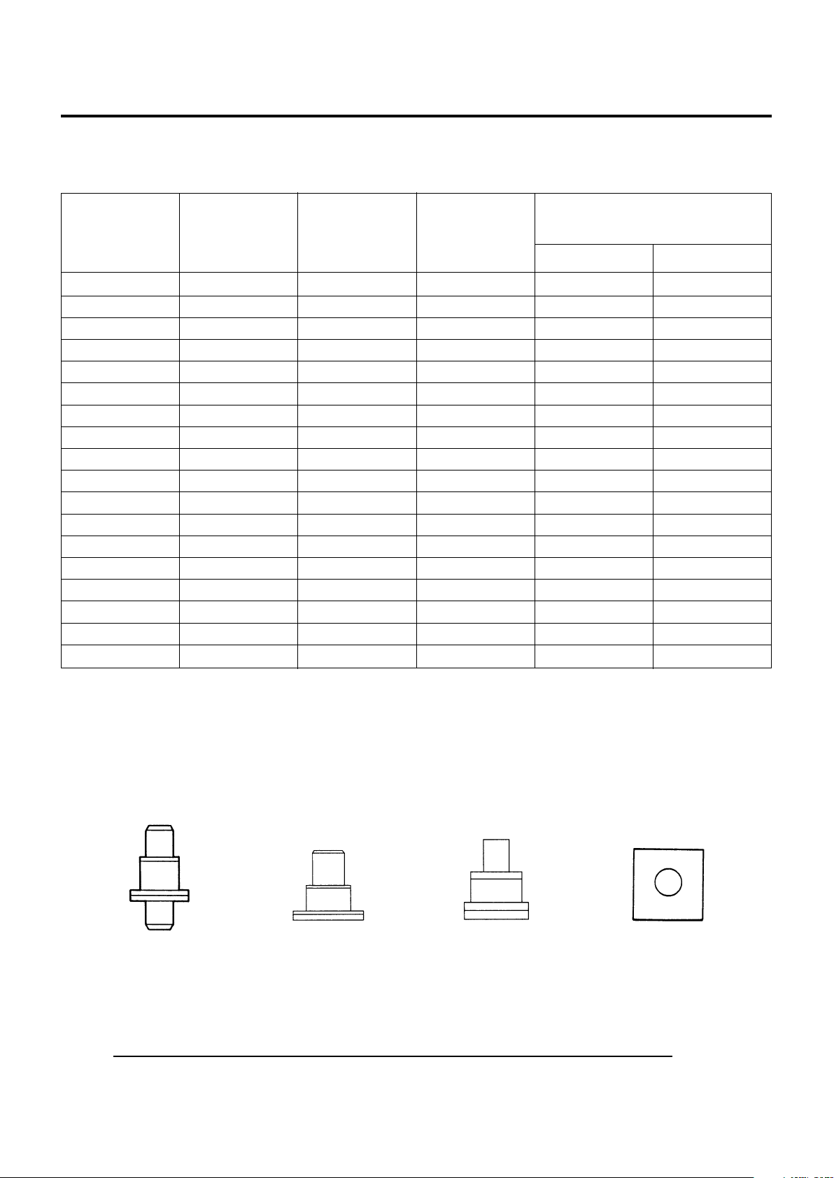
Case styles (See appendix for complete dimensions)
91
103
SOT-23 (High Profile)
Page 4

M/A-COM, Inc.
North America: Tel. (800) 366-2266 ■ Asia/Pacific: Tel. +81 (03) 3226-1671 ■ Europe: Tel. +44 (1344) 869 595
Fax (800) 618-8883 Fax +81 (03) 3226-1451 Fax +44 (1344) 300 020
4
Specifications Subject to Change Without Notice.
V3.00
Step Recovery Diodes MA43000, MA44600, MA44700 Series
Notes:
1. The standard case styles are indicated for each model number. For
other available case styles, consult the factory.
2. This is an operable output frequency range and does not imply instantaneous bandwidth.
Min./Max.
4
Maximum
2
Min./Max.
3
Junction Min./Max. Maximum Maximum Nominal
2
Input Reverse Capacitance Carrier Snap Time,T
S
Thermal Output
Model Case
1
Power V oltage V
R
Cj Lifetime,T
L
-10V/10 mA Resistance Frequency
Number Style (Watts) (Volts) (pF) (ps) (ps) jc(C/W) (GHz)
MA43592 30 1.0 25 - 40 0.2 - 0.30 9 - 27 90 70 1 - 12
MA43543 93 1.5 20 - 50 0.2 - 0.55 10 - 25 60 125 2 - 20
Absolute Maximum Ratings @ 25°C
Parameter Absolute Maximum
Temperature Range
Operating Range -65°C to +200°C
-65°C to +125°C (SOT-23 only)
Storage Range -65°C to +200°C
-65°C to +125°C (SOT-23 only)
Environmental Performance
The MA44600 and MA43000 series of diodes in ceramic
packages are capable of meeting the tests dictated by the
methods and procedures of the latest revisions of MIL-S19500, MIL-STD-202 and MIL-STD-750 which specify
mechanical, electrical, thermal and other environmental
tests common to military semiconductor products.
Electrical Specifications @ 25° C (Cont’d)
High Order Step Recovery Diode Varactors for Use in Comb Generation
Case Styles (See appendix for complete dimensions)
3. Breakdown voltage is measured at a reverse bias voltage of 10 µA.
4. Junction capacitance is measured at a reverse bias voltage of 6 volts
and a frequency of 1 MHz.
30
93
 Loading...