

Page 1

MA02104AF
3.6V 1.2W RF Power Amplifier IC
for N-PCS/ISM900
Applications
Two-Way Paging
Wireless Modems
Cordless Telephones
Telemetry
900 MHz ISM
V
DD1
N/C
GND
GND
RF IN
GND
GND
N/C
V
DD2
GND
GND
GND
RF OUT/V
GND
GND
N/C
DD3
Features
•= Single Positive Supply
•= 16 Pin TSSOP Plastic Package
•= Class AB Bias
•= 800 - 1000 MHz Operation
•= 50Ω Input Impedance
•= Single Capacitor Output Match
•= Self-Aligned MSAG
•= Guaranteed Stability and Ruggedness
®
-Lite MESFET Process
Typical 3.6 Volt Performance
30.8 dBm Power Output
30.8 dB Power Gain
60% Drain Efficiency (output stage FET)
45% Power Added Efficiency
-36 dBc 2nd Harmonic
-54 dBc 3
rd
Harmonic
ELECTRICAL CHARACTERISTICS V
Characteristic Symbol Min Typical Max Unit
=3.6 V, PIN=0 dBm, TS=40 °C (Note 1), Output externally matc hed to 50 Ω System.
DD
Frequency Range ƒ 900 942 MHz
Output Power, f = 900 MHz P
Power Added Efficiency , f = 900 MHz
Harmonics 2ƒ
30.4 30.9 31.5 dBm
OUT
η
o
3ƒo
40 45 %
−36
−54
-31
-40
dBc
dBc
Input VSW R — 1.4:1 2.0:1 —
Thermal Resistance (Junction of 3
pin 13)
Load Mismatch (V
Stability (P
Load VSWR = 8:1)
Note 1: TS is the temperature measured at the soldering point of pin 13, mounted on 60 mil GETEK evaluation board in a free air condition with
= -15 to +3 dBm, VDD = 3.6, 4.6 V, TS = -40 to +100 °C,
IN
ambient room temperature T
under room temperature conditions and CW operation, unl ess otherwise specified.
= 4.6 V, P
DD
rd
stage FET to solder point of
= +3 dBm, VSWR = 8:1) —
IN
=25 °C. The electrical data pres ent ed herei n was t aken with the evaluation board shown in Figures 1 and 6,
A
47 °C/W
R
TH J-S
No Degradation in Power Output
—
All non-harmonically related outputs
more than 60 dB below desired signal
Specifications subject to change without notice.
North America: Tel. (800)366-2266, Fax (800)618-8883
Asia/Pacific: Tel. +81-44-844-8296, Fax +81-44-844-8298
Europe: Tel. +44 (1344) 869 595, Fax +44 (1344) 300 020
Visit www.macom.com for additional data sheets and product information
901753 G
Page 2
3.6V 1.2W RF Power Amplifier IC for N-PCS/ISM900 MA02104AF
V
(
)
MAXIMUM RATINGS (T
Rating Symbol Value Unit
DC Supply Voltage (Pins 1, 12, 16) V
RF Input Power PIN 4 mW
Junction Temperature TJ 150 °C
Storage Temperature Range T
APPLICATION INFORMATION
DD
+
+3.6V
= 25 °C unless otherwise noted)
A
C1 C2
5 Vdc
DD
-40 to +150 °C
STG
INPUT
RF
C3
1
2
N/C
3
4
5
6
7
8
N/C N/C
16
15
14
13
12
T1
11
10
9
L1
C4
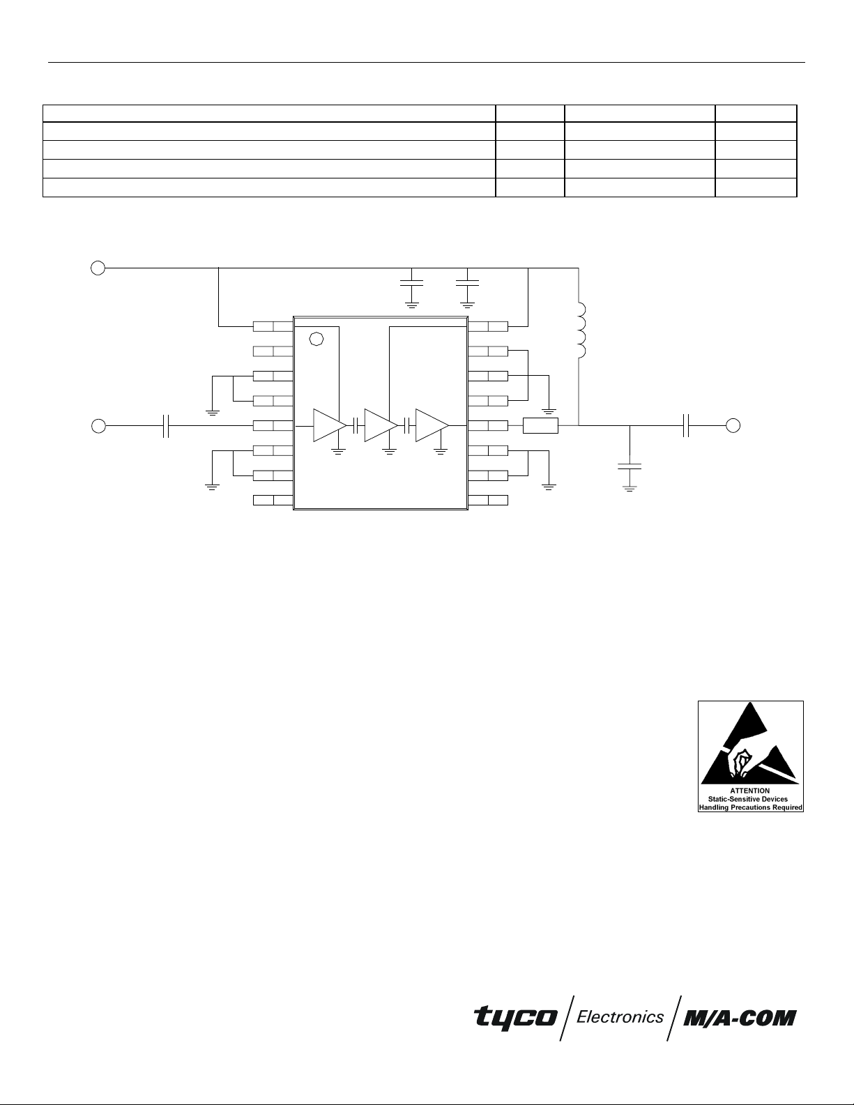
Figure 1. Evaluation Board Schematic
List of components:
C1 = 0.1µF Kemet multilayer ceramic chip capacitor ( C1206C104K5RAC)
C2 = 4700 pF Kemet multilayer ceramic chip capacitor (C0805C472K5RAC)
C4 = 7.5 pF DLI multilayer ceramic chip capacitor (C11AH7R5B5T XL)
C3 = C5 = 100 pF DLI multilayer ceramic chip capacitor (DC Block ; C11AH101K5TXL)
L1 = 39 nH Coilcraft chip inductor (1008CS.390XMBB)
T1 = 0.13" of 50 Ω==g r ounded coplanar waveguide (60 m il GETEK board)
OUTPUT
RF
C5
Component layout and printed circuit board drawing for RF IC evaluation board are shown in Figure 6.
Specifications subject to change without notice.
North America: Tel. (800)366-2266, Fax (800)618-8883
Asia/Pacific: Tel. +81-44-844-8296, Fax +81-44-844-8298
Europe: Tel. +44 (1344) 869 595, Fax +44 (1344) 300 020
Visit www.macom.com for additional data sheets and product information
901753 G
Page 3

3.6V 1.2W RF Power Amplifier IC for N-PCS/ISM900 MA02104AF
η
TYPICAL CHARACTERISTICS
40
80
60
3:1
35
30
25
20
15
, Output Power (dBm)
OUT
10
P
5
0
-10 -5 0 5
, Input Power (dBm)
P
IN
P
OUT
ƒ = 920 MHz
V
η
= 3.6 V
DD
70
60
50
40
30
20
10
0
50
40
(%)
η
30
(dBm) and
20
OUT
η,=Pwr Added Efficiency=(%)
P
VSWR
10
0
800 850 900 950 1000
ƒ,=Frequency (MHz)
P
OUT
2:1
1:1
Figure 2. Output power and efficiency vs. input power Figure 3. Output power, efficiency and input VSWR vs .
frequency
40
35
30
25
80
70
P
OUT
60
50
40
30
20
10
ƒο = 920 MHz
= 0 dBm
P
IN
= 3.6 V
V
DD
20
15
, Output Power dBm)
OUT
P
10
5
η
ƒ = 920 MHz
= 0 dBm
P
IN
0
0.0 0.5 1.0 1.5 2.0 2.5 3.0 3.5 4.0 4.5 5.0
V
, Supply Voltage (Volts)
DD
Figure 4. Output power and efficiency vs. supply
voltage
Specifications subject to change without notice.
North America: Tel. (800)366-2266, Fax (800)618-8883
Asia/Pacific: Tel. +81-44-844-8296, Fax +81-44-844-8298
Europe: Tel. +44 (1344) 869 595, Fax +44 (1344) 300 020
40
30
20
10
0
0
-10
, Output Power (dBm)
OUT
-20
, Pwr Added Efficiency (%)
η
P
-30
-40
ƒο 2ƒο 3ƒο 4ƒο 5ƒο
Frequency
Figure 5. Harmonics
901753 G
Visit www.macom.com for additional data sheets and product information
Page 4

3.6V 1.2W RF Power Amplifier IC for N-PCS/ISM900 MA02104AF
MECHANICAL DATA
Top view
Figure 6. Component layout and printed circuit drawing for evaluation board
50ΩΩΩΩ lead transition
0
7
1
0
180
0
7
1
1000 MHz
-
0
6
1
-
0
0.2
915 MHz
7.2 - j11.2ΩΩΩΩ
5
1
-
0
4
-1
0
3
1
-
800 MHz
0
2
1
-
0.5
0
1
1
-
1
0
0
1
-
-90
-
8
0
Figure 7. Output match impedance (as seen from pin 12)
Specifications subject to change without notice.
North America: Tel. (800)366-2266, Fax (800)618-8883
Asia/Pacific: Tel. +81-44-844-8296, Fax +81-44-844-8298
Europe: Tel. +44 (1344) 869 595, Fax +44 (1344) 300 020
Visit www.macom.com for additional data sheets and product information
901753 G
 Loading...