

Page 1
MITSUBISHI SOUND PROCESSOR ICs
0
SSEERRIIEES
S
PRELIMINARY
M65854FP
Notice ; This is not a final specification.
some parametric limits are subject to change.
DESCRIPTION
The M65854 is a CMOS IC built-in Digital Echo function with microphone peripheral circuits for
"Karaoke" equipment packed in a single chip.
It is suitable for "Karaoke" equipments such as Video CD Player, Mini Stereo, CD-Radio Cassette, TV
or VCR.
FEATURES
• High performance digital echo circuit thanks to 16Kbit memory
• Built-in surround function which works Simulated Stereofor
monaural source and Stereo Surroundfor stereo source
• ALC-equipped microphone amplifiers permit excessively
high input. ALC operating voltage can be set as desired.
• 2 microphone volumes and echo effect volume are included
• Stereo microphone-line mixing amplifiers
• Karaoke entertainment functions such as vocal cut and
automatic vocal support system
• Built-in current-control oscillation circuit
• Built-in automatic reset circuit activated with power on
• The use of AUDIO SW easy to control without Microcomputer
• 5V single power supply
RECOMMENDED OPERATING CONDITION
• Supply voltage range • • • • • • • • • •Vcc = 4.5 ~ 5.5V
Rated supply voltage • • • • • • • • • • Vcc = 5V
DIGITAL ECHO WITH MICROPHONE MIXING CIRCUIT
PIN CONFIGURATION
MCLKCONT
MIC1NFIN
MIC1OUT
MIC1VOLIN
MIC2NFIN
MIC2OUT
MIC2VOLIN
MIC OUT
LPF1IN1
LPF1IN2
LPF1OUT
ADINTOUT
ADINTIN
ADCONT
MIC1IN
ALC1
MIC2IN
ALC2
REF
GND
VCC
1
2
3
M 6 5 8 5 4 F P
4
5
6
7
8
9
10
11
12
13
14
15
16
17
18
19
20
21
5
KARAOKE
42
MIC1VOL
MIC2VOL
41
ECHOVOL
40
AUDSW5
39
AUDSW4
38
AUDSW3
37
AUDSW2
36
AUDSW1
35
PS2
34
PS1
33
LOUT
32
ROUT
31
VCFIL
30
LIN
29
RIN
28
LPF2OUT
27
LPF2IN2
26
LPF2IN1
25
DAINTOUT
24
DAINTIN
23
DACONT
22
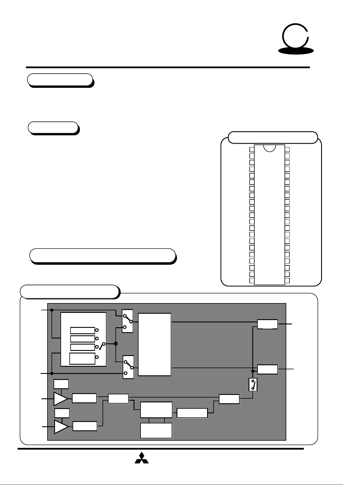
SYSTEM CONFIGURATION
Lch
INPUT
Rch
INPUT
ALC
MIC
MIC
ALC
SOURCE
SELECTOR
L
R
(L+R)/2
VOCAL
CUT
MIC VOLMIC VOL
MIC VOL
MIC VOL
MIX
PHASE
SHIFTER
SURROUND
ECHO
FEEDBACK
VOL
MITSUBISHI
ELECTRIC
ECHO VOL
MIX
MIX
MIX
( / 1 4 )
1
Lch
OUTPUT
Rch
OUTPUT
Page 2
MITSUBISHI SOUND PROCESSOR ICs
0
SSEERRIIEES
S
PRELIMINARY
Notice ; This is not a final specification.
some parametric limits are subject to change.
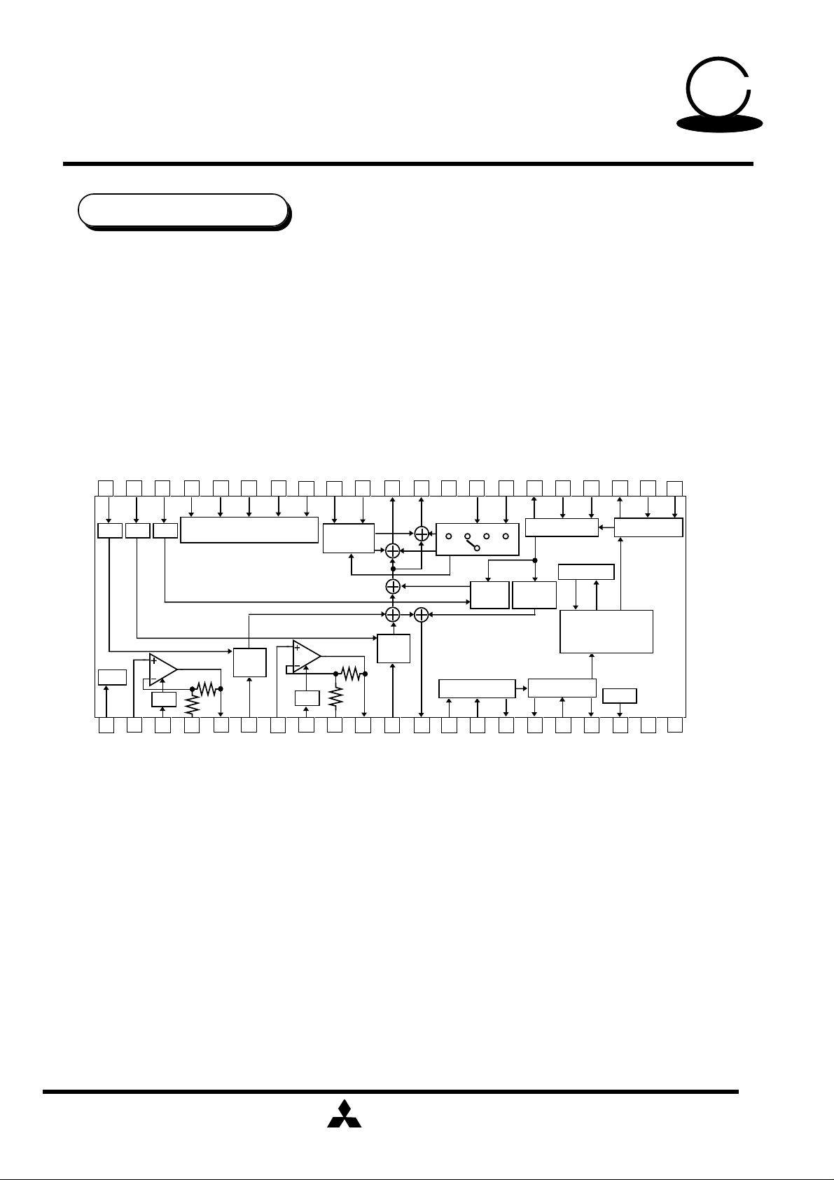
PIN CONFIGURATION
MIC2VOL
MIC1VOL
42 41
DIGITAL ECHO WITH MICROPHONE MIXING CIRCUIT
AUDSW5
39 38
AUDSW4
AUDSW3
37
AUDSW2
AUDSW1
36
35
ECHOVOL
40
34
PS2
PS1
33 32
LOUT
31 30
M65854FP
VCFIL
ROUT
LIN
29
LPF2OUT
RIN
28
27 25 24 23
LPF2IN2
26
DAINTOUT
LPF2IN1
5
KARAOKE
DACONT
DAINTIN
22
A/D A/D A/D
MCLK
ALC
2
1
MIC1IN
MCLKCONT
3
ALC1
AUDIO SW I/F
56 7
4
MIC1OUT
MIC1NFIN
MIC
VOL
MIC2IN
MIC1VOLIN
ALC
8
PHASE
SHIFTER
910
ALC2
MIC
VOL
11 12 13
MIC2OUT
MIC2NFIN
(L+R) / 2 L R
MICOUT
LPF1IN1
MIC2VOLIN
STEREO
ECHO
VOL
LPF
14 15
LPF1IN2
LPF
16kSRAM
ECHO
F.B(-2dB)
A/D
16
17
LPF1OUT
ADINTOUT
MAIN LOGIC
1/2Vcc
18 19
ADINTIN
ADCONT
D/A
GND
REF
20
Vcc
21
GND
VCC
MITSUBISHI
ELECTRIC
2
( / 1 4 )
Page 3
MITSUBISHI SOUND PROCESSOR ICs
0
O
O
O
O
O
SSEERRIIEES
S
PRELIMINARY
Notice ; This is not a final specification.
some parametric limits are subject to change.
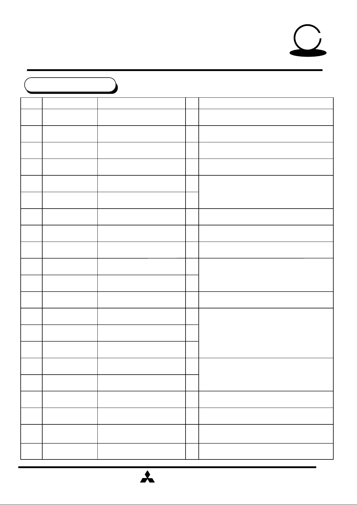
PIN DESCRIPTION
Pin No.
1
2
3
4
5
6
7
Symbol Nam I/O Function
MCLKCONT
MIC1IN
ALC1
MIC1NFIN
MIC1OUT
MIC1VOLIN
MIC2IN
DIGITAL ECHO WITH MICROPHONE MIXING CIRCUIT
Clock control
Microphone 1 input
ALC1 control
Microphone 1 negative
feedback input
Microphone 1 input
Microphone 1 volume input
Microphone 2 input
M65854FP
Controls built-in clock generation circuit with
—
external R
I
To connect MIC1
To connect ALC attack / recovery time
—
setting capacitor
To connect low cut-off frequency of MIC1
I
amplifier setting capacitor
To connect capacitor to reduce noise generated
at time of volume change
I
I
To connect MIC2
5
KARAOKE
8
9
10
11
12
13
14
15
16
17
18
ALC2
MIC2NFIN
MIC2OUT
MIC2VOLIN
MICOUT
LPF1IN1
LPF1IN2
LPF1OUT
ADINTOUT
ADINTIN
ADCONT
ALC2 control
Microphone 2 negative
feedback input
Microphone 2 input
Microphone 2 volume input
Microphone output
Low pass filter 1 input 1
Low pass filter 1 input 2
Low pass filter 1output
A/D integrator output
A/D integrator input
A/D control
To connect ALC attack/recovery time
—
setting capacitor
To connect low cut-off frequency of MIC2
I
amplifier setting capacitor
To connect capacitor to reduce noise generated
at time of volume change
I
Mixing output of MIC1 and MIC2
I
Pre-filter before A/D convertor for
I
digital delay
Composes D/A conversion integrator with
external capacitor
I
To determine adaptive time constant of
—
A/D convertor with ADM system
—
19
20
21
REF
GND
VCC
Reference power output
Ground
Power supply
MITSUBISHI
ELECTRIC
To connect 1/2 Vcc output and filter capacitor
—
—
3
( / 1 4 )
Page 4

MITSUBISHI SOUND PROCESSOR ICs
0
r
O
O
O
O
SSEERRIIEES
S
PRELIMINARY
Notice ; This is not a final specification.
some parametric limits are subject to change.
Pin No.
2 2
2 3
2 4
2 5
2 6
2 7
2 8
Symbol
DACONT
DAINTIN
DAINTOUT
LPF2IN1
LPF2IN2
LPF2OUT
RIN
DIGITAL ECHO WITH MICROPHONE MIXING CIRCUIT
D/A control
D/A integrator input
D/A integrator output
Low pass filter 2 input 1
Low pass filter 2 input 2
Low pass filter 2 output
Rch line input
Nam
M65854FP
I/O Function
To determine adaptive time constant of
—
D/A convertor with ADM system
I
Composes D/A conversion integrator with
external capacitor
I
Post-filter after D/A conversion for digital delay
I
I
Rch line input
5
KARAOKE
2 9
3 0
3 1
3 2
3 3
3 4
3 5
3 6
3 7
3 8
3 9
LIN
VCFIL
ROUT
LOU
PS1
PS2
AUDSW1
AUDSW2
AUDSW3
AUDSW5
AUDSW4
I
Lch line input
Vocal cut filte
Rch output
Lch output Lch mixing output
Phase shift input 1
Phase shift input 2
Source selector and
Auto vocal support sw
Auto vocal support sw
Phase shift sw
Lch line input
Processes frequencies lower than the vocal band
—
Rch mixing output
I
Determines a constant at time of phase shift
I
Source selector and Auto vocal support sw
: audio signal is selected by setting these
I
switches to L or H
Auto vocal support sw : ON set to
I
H,OFF set to L
I
Phase shift sw : ON set to H,OFF set to L
4 0
4 1
4 2
ECHOVOL
MIC2VOL
MIC1VOL
Echo effect volume control
MIC2 volume control
MIC1 volume control
MITSUBISHI
ELECTRIC
Echo effect volume control by DC
I
voltage
I
MIC2 volume control by DC voltage
I
MIC1 volume control by DC voltage
4
( / 1 4 )
Page 5
MITSUBISHI SOUND PROCESSOR ICs
0
SSEERRIIEES
S
PRELIMINARY
Notice ; This is not a final specification.
some parametric limits are subject to change.
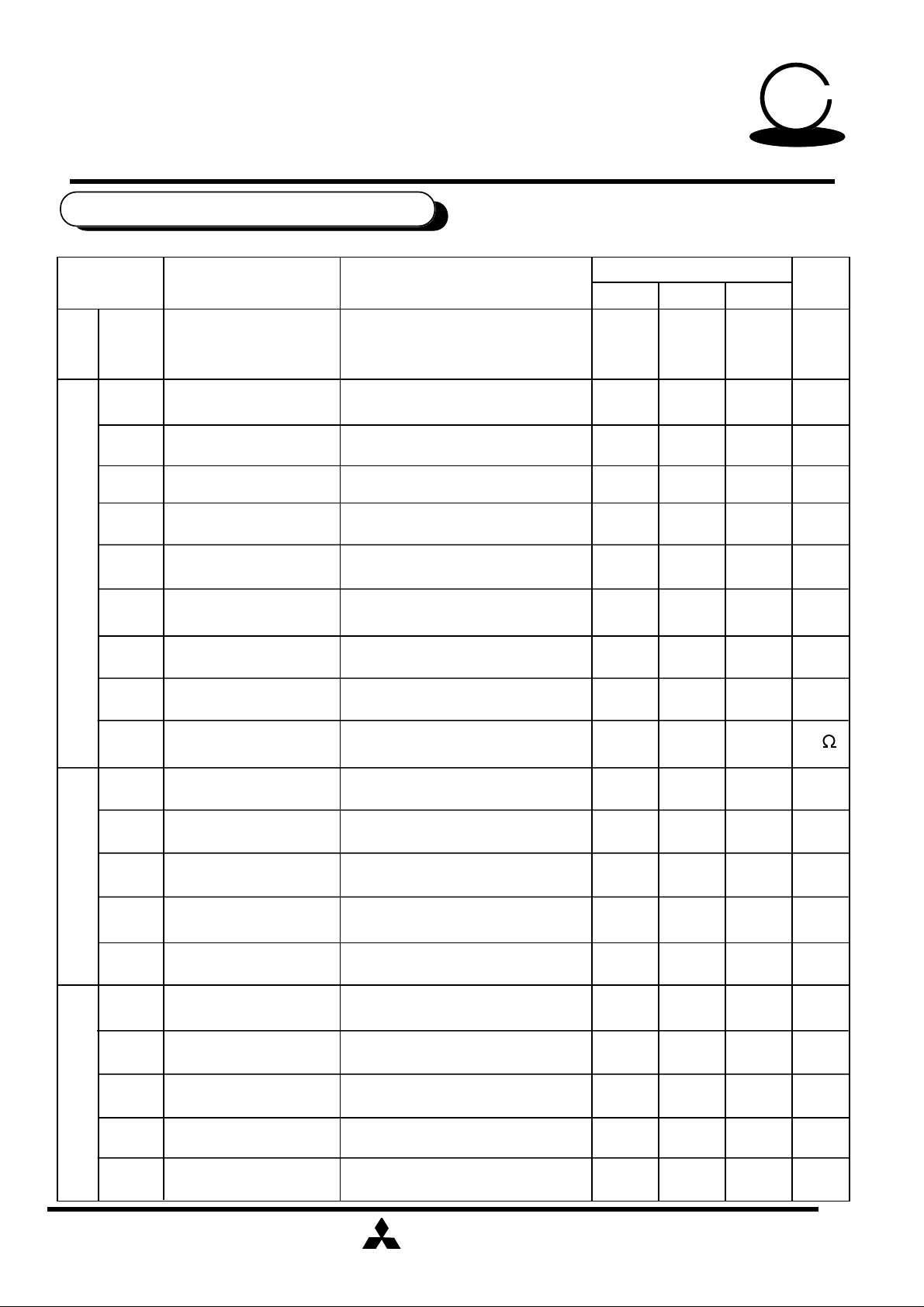
ELECTRICAL CHARACTERISTICS
Symbol Parameter Test conditions
Icc
TOTAL
Gvo Amplifier gain
THD1
THD2 Distortion Vi= -37dBV,with ALC operated
VoALC
DIGITAL ECHO WITH MICROPHONE MIXING CIRCUIT
( Vcc=5V,f=1kHz,vi=100mVrms,Ta=25°C Unless otherwise noted )
Circuit current
Distortion Vo = -17dBV,with ALC not operated
ALC operating voltage
No signal provided
Vo = -17dBV
measurement : +2dBV
M65854FP
Limits
Min Typ Max
—
—
—
0
35
47
0.1
3.0
5
KARAOKE
Unit
mA
dB
0.5
6.0
+2 dBV
+4
%
%
TALCAT
TALCRE ALC recovery time C=4.7µF
Microphone amplifier
VoMAX
No
Zi
Gv I/O voltage gain Volume max
ATTmax Maximum attenuation
THD Distortion Volume max
Mic volume
Gv I/O voltage gain Volume max
ALC attack time
Maximum output voltage
Output noise voltage
Input impedance
Maximum input voltageViMAX
Output noise voltage JIS - ANo
C=4.7µF
THD=10%
Gv=47dB,f=100 to 5KHz
Volume min
THD=10%
25
1.0
1.2
—
5
-3
—
—
1.3
—
-3
40
1.5 sec
1.3
-68
10
0
-72
0.15
1.6
55
2.0
—
-57
20
+3
-67
0.30
—
msec
Vrms
dBV
K
dB
dBV
Vrms
-96 dBV-90
0
+3
dB
%
ATTmax Maximum attenuation
THD Distortion Volume max
Maximum output voltageVoMAX
volume
Echo effect / Echo feed back
Output noise voltage JIS - ANo
Volume min
THD=10%
MITSUBISHI
ELECTRIC
—
—
—
-72
0.15
1.4
-67
0.30
—
-96 dBV-90
5
( / 1 4 )
dBV
%
Vrms1.1
Page 6

MITSUBISHI SOUND PROCESSOR ICs
0
SSEERRIIEES
S
PRELIMINARY
Notice ; This is not a final specification.
some parametric limits are subject to change.
Symbol Parameter Test conditions
Gv I/O voltage gain
Digital echo
Td Delay Time
DIGITAL ECHO WITH MICROPHONE MIXING CIRCUIT
Maximum output voltage THD=10%VoMAX
Sets Delay time with microcomputer.
M65854FP
Limits
Min Typ Max
-3
1.1
147.4
196.6
5
KARAOKE
+3
—
245.7
Unit
dB0
Vrms1.4
msec
THD Distortion
Digital echo
No
Gv I/O voltage gain
THD Distortion
No
LINE
Output noise voltage
Maximum output voltage
Output noise voltage
Td=196.6mS,30KHzLPF
Vi=0mVrms,JIS - A
Td=196.6msec,Rg=620
30KHzLPF
THD=10%VoMAX
JIS - A,
MIC1VOLandMIC2VOL=0.0V
2.0
-67
-3
—
1.1
-90
2.0 %
-82 dBV
0.02
-95 dBV
4.0
—
+3
0.04
—
—
dB0
%
Vrms1.7
Channel separation Lin=400Hz,Rout JIS - ACS
Zi Input impedance
Vocal removal ratio Vocal cutGrej
MITSUBISHI
ELECTRIC
10
14
-70 dB
20 KHz
18 dB
( / 1 4 )
30
—
6
Page 7

MITSUBISHI SOUND PROCESSOR ICs
0
SSEERRIIEES
S
PRELIMINARY
Notice ; This is not a final specification.
some parametric limits are subject to change.
ABSOLUTE MAXIMUM RATINGS
Symbol Name Test conditions Ratings Units
Vcc
Vi
Pd
Topr
Tstg
DIGITAL ECHO WITH MICROPHONE MIXING CIRCUIT
Supply voltage
Circuit current
Input Voltage
Operating
temperature
Storage
temperature
M65854FP
6.0
-0.3 ~ Vcc+0.3
1.1
-20 ~ +75
-40 ~ +125
5
KARAOKE
V
V
W
°C
°C
RECOMMENDED OPERATING CONDITION
Symbol Parameter Test conditions
Min Typ Max
VDD V4.5 5
VIL
VIH
Digital
supply voltage
L input level
H input level
0
0.7VDD
Limits
—
—
5.5
0.3VDD
VDD
Units
V
V
MITSUBISHI
ELECTRIC
7
( / 1 4 )
Page 8

MITSUBISHI SOUND PROCESSOR ICs
0
SSEERRIIEES
S
PRELIMINARY
Notice ; This is not a final specification.
some parametric limits are subject to change.
FUNCTION CONTROL
• SOURCE SELECTOR SWITCH
AUDSW3 AUDSW1
LL
LL
LH
LH
HL
HHH
• AUTO VOCAL SUPPORT SWITCH
DIGITAL ECHO WITH MICROPHONE MIXING CIRCUIT
Control Data
AUDSW2
L
H
L
H
L
Source select
Lch, monaural
Rch, monaural
(L+R) / 2
Vocal cut
Stereo
TEST MODE
• PHASE SHIFTER SURROUND CONTROL
M65854FP
5
KARAOKE
Control Data
AUDSW4
L
H
• Microphone volume attenuation
DC voltage control (V)
MIC2VOL(pin41)
MIC1VOL(pin42)
AUTO VOCAL SUPPORT
Auto vocal support SW
OFF
ON
Attenuation [dB]
5.0
4.0
3.5
3.0
2.5
2.0
1.5
1.0
0.0
• Digital echo output control
Control Data
MIC1VOL
—
0.0 (V)
MIC2VOL
—
0.0 (V)
Digital echo output control
0
-3
-6
-9
-12
-15
-18
-
Control Data
AUDSW5
L
H
• Echo effect volume attenuation
DC voltage control (V)
ECHOVOL(pin40)
PHASE SHIFTER SURROUND
5.0
4.0
3.5
3.0
2.5
2.0
1.5
1.0
0.0
Note:
When the MIC1VOL and MIC2VOL are
— at the same time, the Digital echo
output control will automatically be the
ON
OFF
Digital echo output off mode.
Please use the Digital echo output
control for Mic sw.
Surround SW
OFF
ON
Attenuation [dB]
+3
0
-3
-6
-9
-12
-15
-
MITSUBISHI
ELECTRIC
8
( / 1 4 )
Page 9

MITSUBISHI SOUND PROCESSOR ICs
0
SSEERRIIEES
S
PRELIMINARY
M65854FP
Notice ; This is not a final specification.
some parametric limits are subject to change.
FUNCTION DESCRIPTION
(1) AUTO RESET
Settings are reset automatically when the IC is powered up. The reset state is
automatically canceled approximately 150msec after powering up(Vcc=5V and the
capacitor connected to pin C=100µF).
By auto reset, operation mode setting become as follows.
•Source Selector : stereo
•Phase Shifter Surround Control : OFF •Auto Vocal support Switch : OFF
•Echo effect Volume : —
DIGITAL ECHO WITH MICROPHONE MIXING CIRCUIT
•Microphone Volume Attenuation : -10dB
5
KARAOKE
(2) AUTO MUTE FUNCTION
The IC carries out auto mute function at the time of powering up in order to suppress
shock noise that the digital delay may produce.
•At power up
Mute time
Reset Time
(400msec)
MITSUBISHI
ELECTRIC
( / 1 4 )
9
Page 10

M65854FP
MITSUBISHI SOUND PROCESSOR ICs
The gain(Gv) and low cut-off frequency(fcl) of microphone amplifier are expressed
as follows.
1
The delay time (Td) for echo is determined by the clock
frequency (fck).
DIGITAL ECHO WITH MICROPHONE MIXING CIRCUIT
(3) Clock oscillator circuit
This IC incorporates a current control type clock oscillator circuit in it, thus providing
circuit configuration just by connecting an Rc for current control pin 1 (MCLKCONT).
Fully internal clock supply prevents occurrence of undesired radiation without affecting
any external circuit.
The oscillator frequency fck is following.
fck = 4 MHz(Rc=22K )
Note:
DC Current
Rc
1
Clock
oscillator
circuit
50
KARAOKE
S E R I E S
S E R I E S
Clock frequency:fck
(4) Microphone amplifier
Gv=20log•
R1+1.5K+334K
R1+1.5K
fcl=
2π•(R1+1.5K)•C1
Gv(max)=47dB,fcl=225Hz
R1=0 ,C1=0.47µF
Assuming Gv=37dB, fcl=220Hz,for instance,
the constants take the following values.
R1=3.3K ,C1=0.15µF
fck = 4 MHz(Rc = 22K )
Delay time = 196.6msec
Delay time = 1/fckX48XN
(N = the number of memory bits = 16384
REF
10k (typ)
0.22µF
MIC
2
10k
1.5k
4
R1
334k
5
MITSUBISHI
ELECTRIC
C1
1 0
( / 1 4 )
Page 11

M65854FP
DIGITAL ECHO WITH MICROPHONE MIXING CIRCUIT
Quality factor (Q) is given by the following equation for long echo.
(5)ALC level diagram
Vo(dBV)
10
+2
0
-10
MITSUBISHI SOUND PROCESSOR ICs
ALC OPERATING VOLTAGE SETTING RANGE
50
KARAOKE
S E R I E S
S E R I E S
-20
-30
-70
MICROPHONE AMPLIFIER GAIN SETTIG=47dB
-50 -40 -30 -20
-60
Vi(dBV)
-10
(6) Input and output LPF for the digital echo
The input and output LPF for the digital echo are configured as shown.
figure below.
C2:1000pF
C1:4700pF
13
14
15
24k
24k
24k
Input
The accuracy of the internal resistance of the IC is approximately ±30%
Cut-off frequency(fc) is given as follows.
fc=
2π X 24k X
1
Q=
C1
3
C2
1
C1 X C2
0.72 (Figure of 0.7 is recommended)
=
2π X 24k X
MITSUBISHI
ELECTRIC
1
4700pF X 1000pF
Output
3.1KHz
( / 1 4 )
1 1
Page 12

M65854FP
MITSUBISHI SOUND PROCESSOR ICs
Signal Detection
vocal cut
50
KARAOKE
DIGITAL ECHO WITH MICROPHONE MIXING CIRCUIT
(7) Auto vocal support
If you can not continue sing a song, the reference vocal from the source will support you
automatically.
Source selector mode
Stereo
On
Lch monaural
Rch monaural
(L+R)/2
S E R I E S
S E R I E S
Off
(L+R)/2
The timing of microphone input signal detection
Microphone
input
level output
release time 1.5s
(L+R)/2
same as
above
Reference
level
(REF+20mV)
attack time 0s
microphone
signal
detection
On
MITSUBISHI
ELECTRIC
OFF
On
1 2
( / 1 4 )
Page 13

M65854FP
DIGITAL ECHO WITH MICROPHONE MIXING CIRCUIT
Surround
The sound components of the same phase and same sound volume in the L and R
channels are attenuated.
This made also allows components with lower frequency than the vocal band to pass
through the filter, to compensate insufficient low-frequency sound.
vocal cut block
(8) Vocal cut support
Lch INPUT
Rch INPUT
fvc=
2πCR
LPF is formed by the internal R (20k ) and the external C,
where C=0.15µF , cut off frequency is 53Hz.
MITSUBISHI SOUND PROCESSOR ICs
S E R I E S
S E R I E S
50
KARAOKE
OUTPUT
30
C
1
=53.0Hz
0.15µ
(9)Following is the phase shifter block, which makes phase surround effect.
Phase Shifter
Lch INPUT
33
C(external)=0.022µF
34
Rch INPUT
Source selector Surround
L
R
Simulated Stereo
(L+R)/2
Lch OUTPUT
Rch OUTPUT
Vocal cut
Stereo
MITSUBISHI
ELECTRIC
Stereo Surround
( / 1 4 )
1 3
Page 14

MITSUBISHI SOUND PROCESSOR ICs
0
k
SSEERRIIEES
S
PRELIMINARY
Notice ; This is not a final specification.
some parametric limits are subject to change.
APPLICATION EXAMPLE
MIC2VOL
MIC1VOL
42
41
DIGITAL ECHO WITH MICROPHONE MIXING CIRCUIT
AUDSW5
ECHOVOL
40
39 38 37
AUDSW4
AUDSW2
AUDSW3
36
35 34
AUDSW1
0.022µ
33
LOUT ROUT
1µ
1µ
32
31 30 29
M65854FP
LIN RIN
0.15µ
1µ 1µ
0.001µ
28
2627
25 24 23 22
0.0047µ
0.068µ
5
KARAOKE
0.1µ
A/D A/D A/D
MCLK
1
22
0.22µ
AUDIO SW I/F
MIC
VOL
ALC
23 56789101112131415 17
4.7µ
10 k
MIC1IN
4
1.0µ
4.7µ
0.1µ
0.22µ
10 k
MIC2IN
PHASE
SHIFTER
MIC
VOL
ALC
0.1µ
1.0µ
(L+R) / 2 L R STEREO
0.022µ
0.0047µ
ECHO
VOL
LPF
0.001µ
ECHO
F.B(-2dB)
16 18 19 20
0.068µ
LPF
16kSRAM
MAIN LOGIC
A/D
0.1µ
100µ
1/2Vcc
D/A
GND
Vcc
21
100µ
0.1µ
MITSUBISHI
ELECTRIC
Unit R:
C:F
( / 1 4 )
1 4
 Loading...