

Page 1
MITSUBISHI SOUND PROCESSOR ICs
SERIES
PRELIMINARY
Notice ; This is not a final specification.
some parametric limits are subject to change.
DIGITAL ECHO(DIGITAL DELAY)
M65850P/FP
SERIES
50
KARAOKE
DESCRIPTION
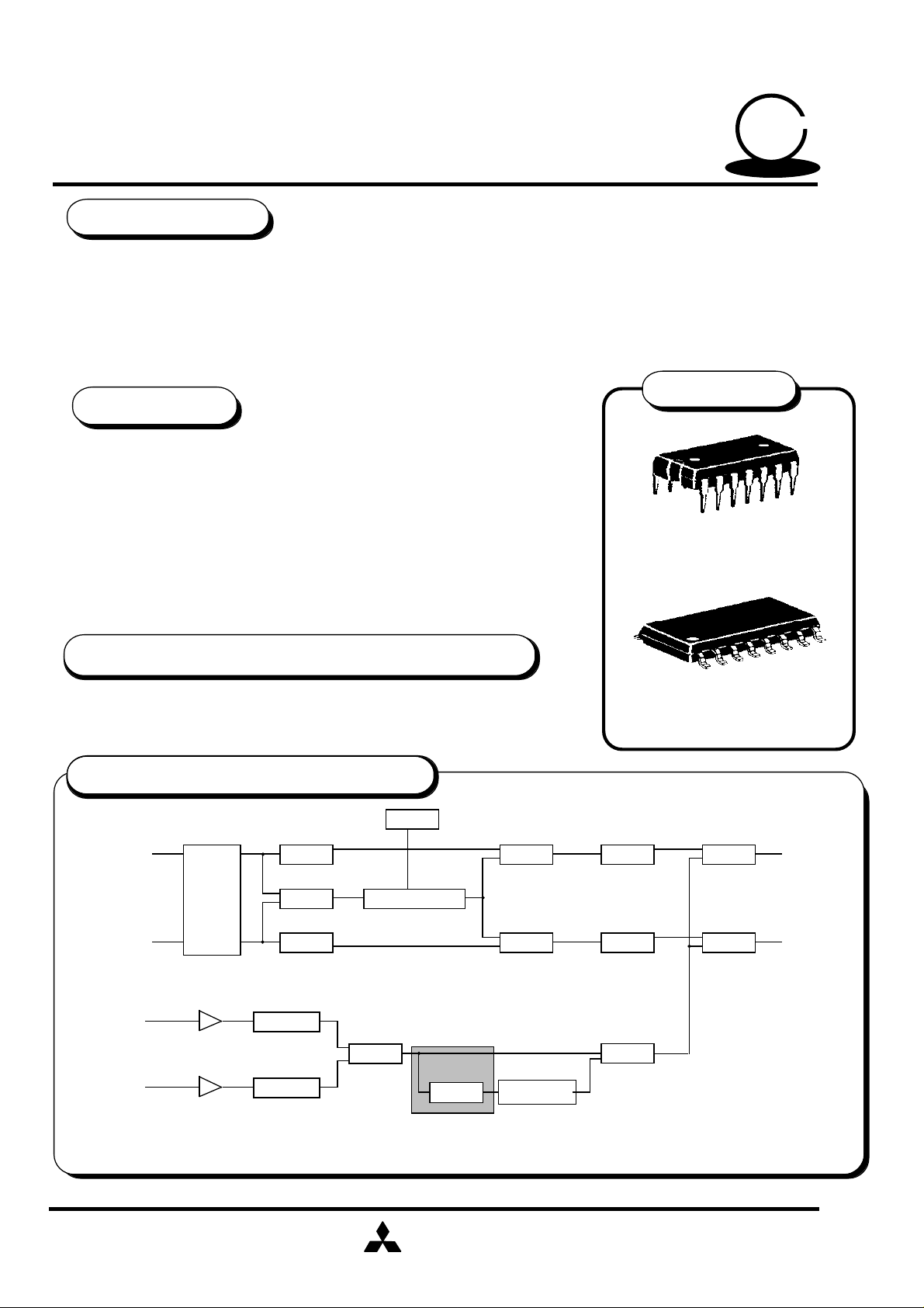
◊ The M65850P/FP is a CMOS IC for generating echo to be added to the voice through a
"karaoke" microphone.
◊ It is optimal to provide the echo effect function for karaoke player, such as radio cassette
recorders, mini audio components and television sets.
◊ Increased master clock frequency assures high-performance short delay,enabling the IC
to be used for dolby prologic surround system.
PACKAGE
FEATURES
• Built-in input/output filters, A-D and D-A converters,and memory
realize a delay system with only a single chip.
• Built-in current control type clock oscillator circuit avoids clock
affection outside,thus allowing prevention of undesired radiation.
• Delay time = 164 ms (with master clock set at 1MHz)
(Selection of delay time in a range between 15ms and 200ms)
• Small package (14-pin DIP : 14P4,16-pin SOP:16P2N)
• Built-in 20Kbit SRAM
• Built-in auto reset circuit (The IC reset as power is turned on)
• Single power supply (5V)
Outline 1 4 P 4 ( P )
2.54mm pitch 300mil DIP
RECOMMENDED OPERATING CONDITION
Supply voltage range • • • • • Vcc=3.5~5.5V
Rated supply voltage • • • • • • • • • • Vcc=5V
SYSTEM CONFIGURATION
RAM
L
VOCAL
CUT
R
MIC1
MIC AMP
MIC2
MIC AMP
HPF
LPF KEY CONTROL
HPF
MIC VOL
MIX
MIC VOL
M65850P/FP
ECHO VOLECHO
MIX
MIX
Outline 1 6 P 2 N ( FP )
1.27mm pitch 300mil SOP
BASS
BASS
MIX
MIX
MIX
L
R
Note : Dolby is the registered trademarks of dolby laboratories licensing corporation.
MITSUBISHI
ELECTRIC
( / 11 )
1
Page 2
PRELIMINARY
Notice ; This is not a final specification.
some parametric limits are subject to change.
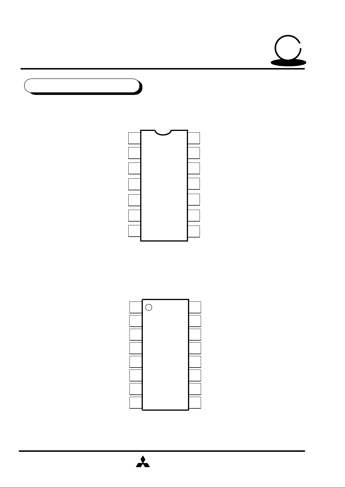
PIN CONFIGURATION
< M65850P >
DIGITAL ECHO(DIGITAL DELAY)
MITSUBISHI SOUND PROCESSOR ICs
M65850P/FP
50
KARAOKE
SERIES
SERIES
LPF1 IN
LPF1 OUT
OP1 OUT
OP1 IN
GND
< M65850FP >
CC1
CC2
1
14
14
VCC
M 6 5 8 5 0 P
CLOCK
2
3
4
5
6
7
13
REF
12
11
OP2 IN
10
OP2 OUT
9
LPF2 IN
8
LPF2 OUT
NC
LPF1 IN
LPF1 OUT
OP1 OUT
OP1 IN
CC1
CC2
GND
1
M 6 5 8 5 0 F P
14
2
3
4
5
6
7
8
MITSUBISHI
ELECTRIC
NC
16
VCC
15
CLOCK
14
REF
13
12
OP2 IN
11
OP2 OUT
10
LPF2 IN
9
LPF2 OUT
( / 11 )
2
Page 3
PRELIMINARY
Notice ; This is not a final specification.
some parametric limits are subject to change.
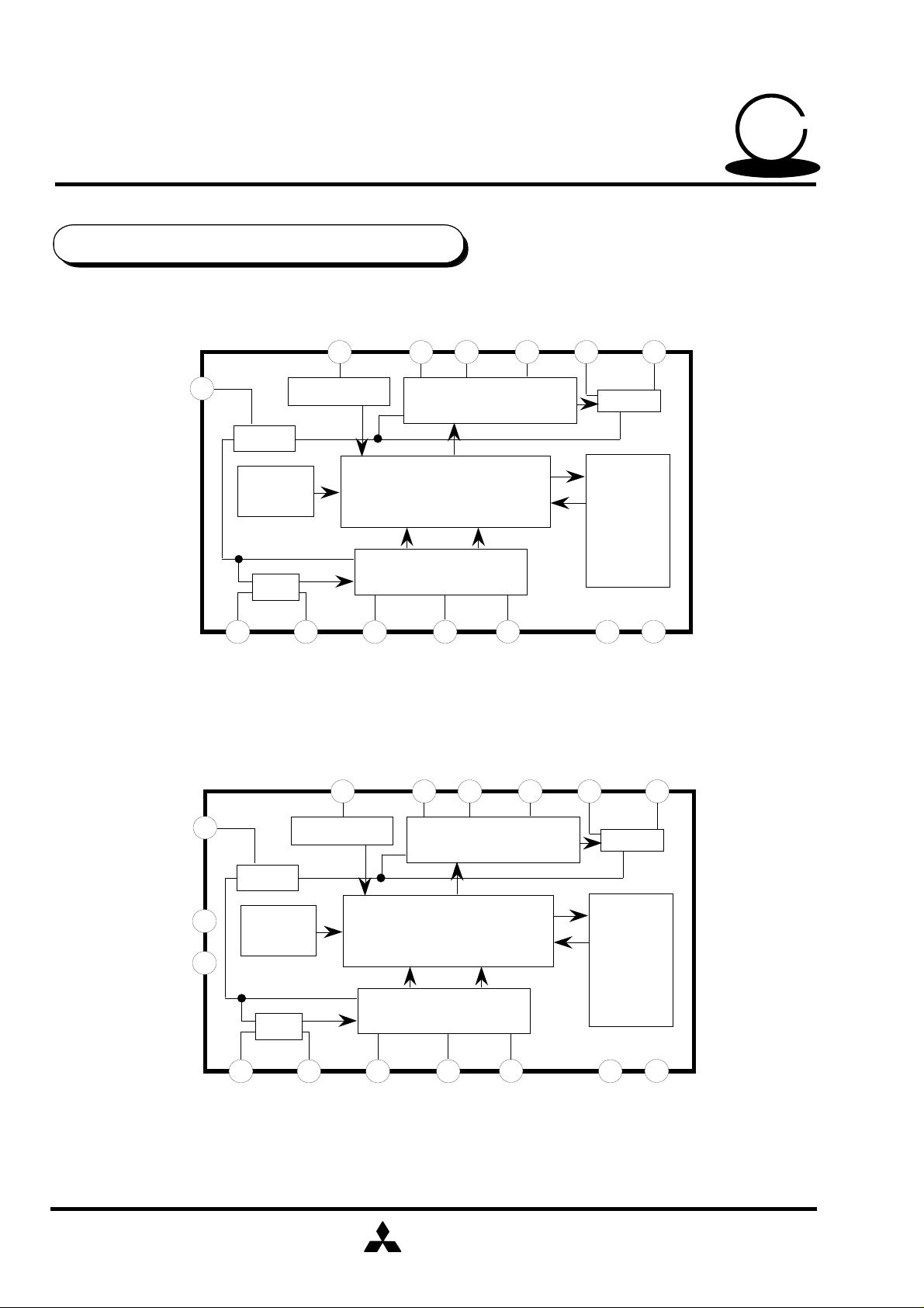
IC INTERNAL BLOCK DIAGRAM
< M65850P >
12
REF
1/2 Vcc
DIGITAL ECHO(DIGITAL DELAY)
CLOCK
13
OSCILLATOR
CLOCK
AUTO
RESET
RESET
M65850P/FP
OP2IN OP2OUT LPF2IN LPF2OUT
CC2
6
D / A
DO1
MAIN CONTROL
D1 DO0
MITSUBISHI SOUND PROCESSOR ICs
SERIES
SERIES
50
KARAOKE
891011
LPF2
MO
M I
20Kbit
SRAM
LPF1
1 142 3 4 5
< M65850FP >
13
REF
1/2 Vcc
NC
NC
16
1
AUTO
RESET
LPF1
LPF1OUTLPF1IN
CLOCK
14
OSCILLATOR
RESET
CLOCK
A / D
OP1INOP1OUT
CC2
OP2IN OP2OUT LPF2IN LPF2OUT
7
DO1
MAIN CONTROL
D1 DO0
A / D
CC1
D / A
MO
M I
7
GND
LPF2
20Kbit
SRAM
VCC
9101112
2 153 4 5 6
LPF1OUTLPF1IN
OP1INOP1OUT
MITSUBISHI
ELECTRIC
CC1
8
GND
VCC
( / 11 )
3
Page 4
PRELIMINARY
Notice ; This is not a final specification.
some parametric limits are subject to change.
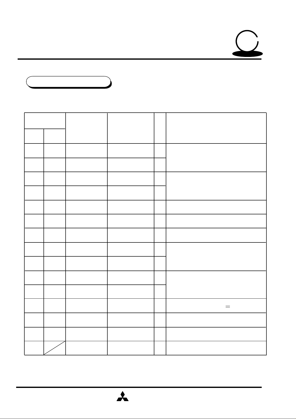
PIN DESCRIPTION
Pin No.
DIGITAL ECHO(DIGITAL DELAY)
MITSUBISHI SOUND PROCESSOR ICs
M65850P/FP
50
KARAOKE
SERIES
SERIES
P FP
1
2
3
4
5
6
7
8
9
10
11
10
11
12
Symbol Name
2
3
4
5
6
7
8
9
LPF1 IN
LPF1 OUT
OP1 OUT
OP1 IN
CC1
CC2
GND
LPF2 OUT
LPF2 IN
OP2 OUT
OP2 IN
Low pass filter 1
input
Low pass filter 1
output
Operational
amplifier1 output
Operational
amplifier 1 input
Current control 1
Current control 2
GND
Low pass filter 2
output
Low pass filter 2
input
Operational
amplifier 2 output
Operational
amplifier 2 input
I/O
Function
I
To form input-side low pass filter by
connecting external capacitor and resistor
O
O
To form A-D conversion integrator by
connecting external capacitor
I
ADM control of A-D converter
-
ADM control of D-A converter
-
-
O
To form input-side low pass filter by
connecting external capacitor and resistor
I
O
To form D-A conversion integrator by
connecting external capacitor
I
I
12
13
14
-
13
14
15
1
16
REF
CLOCK
VCC
NC
Reference
Clock generator
input
Supply voltage
No connection -
MITSUBISHI
ELECTRIC
Analog reference voltage 1/2Vcc
-
To form clock generator by connecting
I
external resistor
To apply 3.5 ~ 5.5 V power
-
(Rated voltage : 5 V)
•
•
( / 11 )
4
Page 5

PRELIMINARY
Notice ; This is not a final specification.
some parametric limits are subject to change.
ABSOLUTE MAXIMUM RATINGS
DIGITAL ECHO(DIGITAL DELAY)
MITSUBISHI SOUND PROCESSOR ICs
M65850P/FP
50
KARAOKE
( Ta = 25°C, unless otherwise noted )
SERIES
SERIES
Symbol Parameter Ratings Unit
Vcc Supply voltage
Icc
Pd
Topr
Tstg
Circuit current
Power dissipation
Operating temperature
Storage temperature
Conditions
6.0
100
800(P),550(FP)
-20 ~ 75
-40 ~ 125
RECOMMENDED OPERATING CONDITION
Limits
Symbol Parameter
Vcc
Supply Voltage
fck Clock frequency
Conditions
Min Typ Max
3.5
5
5.5
0.8 11.0
V
mA
mW
°C
°C
Unit
V
MHz
ELECTRICAL CHARACTERISTICS
(Vcc=5V,f=1kHz,Vi=100mV(rms),fck=1MHz,Ta=25°C, unless otherwise noted)
Limits
Symbol
Icc
Gv
Vomax
THD
No
fck
Parameter
Circuit current
Voltage gain
Maximum output
voltage
Total harmonic
distortion
Output noise voltage
Clock frequency
Test conditions
No signal input
RL=47kΩ
THD=10%
30kHz LPF
DIN-AUDIO
Rc=120kΩ
MITSUBISHI
ELECTRIC
Min Typ
5
-3.0 3.0
0.7
13
0
1.0
1.2
-85
0.85 1.15
1
Max
25
Unit
mA
dB
V(rms)
3.0
-70
%
dBV
MHz
( / 11 )
5
Page 6

MITSUBISHI SOUND PROCESSOR ICs
PRELIMINARY
Notice ; This is not a final specification.
some parametric limits are subject to change.
DIGITAL ECHO(DIGITAL DELAY)
M65850P/FP
FUNCTION DESCRIPTION
(1) Delay time Td
The delay time can be calculated by the equation :
Td=8N / fck ( N=the number of memory bits=20480 )
When fck=1MHz ( fs=125kHz), Td can be set at 164ms.
« Reference »
The M65850P/FP adopts ADM ( Adaptive Delta Modulation ) system in A-D,D-A
converters.
The sampling frequency can be calculated by the following equation :
fs=clock frequency / 8 ( Hz )
For clock frequency ( fck )=1MHz, the calculated sampling frequency is :
fs=1MHz / 8 =125kHz
50
KARAOKE
SERIES
SERIES
(2) Clock oscillator circuit
The M65850P incorporates a current control type clock
oscillator circuit in it, thus providing circuit configuration just by
connecting a resistor for current control to pin 13 ( FP:pin 14 )
CLOCK.
Fully internal clock supply prevents occurrence of undesired
radiation without affecting any external circuit.
The oscillator frequency is:
fck = 1 MHz. ( Rc=120kΩ )
The resistor for current control can be calculated using the
following equation.
Rc K/Clock frequency (fck) [ Hz ]
K is the coefficient, and changes according to clock frequency
,as shown below.
Delay Time
( ms )
15~30
•
•
Clock Frequency
( Hz )
11.0M~5.5M
K value
11
0.8 X 10
Rc
Vcc
*
13
(FP:14)
*
Rc ( Ω )
7.5k~15k
Clock
oscillator
circuit
Clock
frequency : fck
31~100
101~200
5.3M~1.64M
1.62M~800K
1.0 X 10
1.2 X 10
MITSUBISHI
ELECTRIC
11
11
18k~62k
75k~150k
( / 11 )
6
Page 7

PRELIMINARY
Notice ; This is not a final specification.
some parametric limits are subject to change.
(3) Input/output LPF
It is necessary to change the LPF setting ( signal pass band,fsig )
of digital echo according to the clock frequency. ( Refer to the table below )
DIGITAL ECHO(DIGITAL DELAY)
MITSUBISHI SOUND PROCESSOR ICs
M65850P/FP
50
KARAOKE
SERIES
SERIES
(FP:2)
*
R1
LPF1
REF
1 2
R2
* *
C2
R1
C1
•
fsig=
••
(FP:3)
*
1
2π C1 • C2 • R1 • R2
REF
(FP:10)
*
R2
R1
LPF2
* *
9 8
C1
C2
R1
(FP:9)
*
Delay time
( ms )
15~30
31~100
101~200
Clock
frequency( Hz )
11.0M ~ 5.5M
5.3M ~ 1.64M
1.62M ~ 800k
•Test Condition is Vcc=5V,Vi=100mV(rms),f=1kHz,Ta=25°C
signal pass
band ( Hz )
7k
5k
3k
LPF
R1( Ω ) R2 ( Ω ) C1 (F) C2 (F)
15k
13k
16k
MITSUBISHI
ELECTRIC
15k
13k
16k
3300p
4700p
6800p
680p
1000p
1500p
Distortion
(Reference value)
(%)
0.2%
(Td=20ms)
0.3%
(Td=50ms)
1.2%
(Td=160ms)
( / 11 )
7
Page 8

PRELIMINARY
Notice ; This is not a final specification.
some parametric limits are subject to change.
(4) Mute
When power is turned on, the mute function works automatically to
prevent noise generation. (Here, however, "mute" means the
function which prevents noise generation after the reset time.)
DIGITAL ECHO(DIGITAL DELAY)
MITSUBISHI SOUND PROCESSOR ICs
M65850P/FP
50
KARAOKE
SERIES
SERIES
POWER
ON TIME
RESET
PERIOD
TEST CONDITIONS
ParameterSymbol
Icc
Gv
Vomax
Maximum output voltage
Circuit current
Voltage gain between
input and output
MUTE PERIOD
(ABOUT 260ms)
WHEN POWER IS ON (fck=1MHz)
S 1 S 1 4
2
1
1
MUTE
OFF TIME
2
1
1
Remarks
No-signal time
RL=47kΩ
THD=10%
THD
No
Output distortion
Output noise voltage
MITSUBISHI
ELECTRIC
1
2 1
1
30kHz LPF
DIN-AUDIO
( / 11 )
8
Page 9

PRELIMINARY
Notice ; This is not a final specification.
some parametric limits are subject to change.
TEST CIRCUIT
< M65850P >
DIGITAL ECHO(DIGITAL DELAY)
MITSUBISHI SOUND PROCESSOR ICs
M65850P/FP
50
KARAOKE
SERIES
SERIES
47µ
(2)
(1)
(2)
S14
(1)
0.1µ
+
16k
51
16k
1µ
+
S1
6800p
~
Vi
120k
14
VCC
LPF1 IN
1
1500p
16k
47µ
13
CLOCK
LPF1 OUT
2
+
12
REF
OP1 OUT
3
0.068µ
0.068µ
11
OP2 INOP1 IN
4
0.22µ
16k
16k
10
OP2 OUT
CC1
5
0.22µ
6800p
16k
1500p
9
LPF2 IN
CC2
6
8
LPF2 OUT
GND
7
47k
+
1µ
~
Vo
< M65850FP >
47µ
(2)
(1)
(2)
S14
(1)
16k
120k
15
VCC
LPF1 IN
2
1500p
16k
47µ
14
CLOCK
LPF1 OUT
3
0.1µ
+
16
NC
NC
1
51
16k
1µ
+
S1
6800p
~
Vi
0.068µ
+
13
REF
OP1 OUT
4
0.068µ
12
OP2 INOP1 IN
5
0.22µ
16k
16k
11
OP2 OUT
CC1
6
0.22µ
6800p
16k
1500p
10
LPF2 IN
CC2
7
9
LPF2 OUT
GND
8
47k
+
1µ
~
Vo
Units
Resistance : Ω
Capacitance:F
MITSUBISHI
ELECTRIC
9
( / 11 )
Page 10

MITSUBISHI SOUND PROCESSOR ICs
PRELIMINARY
Notice ; This is not a final specification.
some parametric limits are subject to change.
DIGITAL ECHO(DIGITAL DELAY)
M65850P/FP
APPLICATION EXAMPLE
• ECHO Delay time 164ms (Signal pass band 3kHz)
< M65850P >
50
KARAOKE
SERIES
SERIES
+
47µ
IN
1µ
< M65850FP >
47µ
OUT
+
1µ
OUT
+
1µ
12
16k
16k
10
OP2 OUT
CC1
5
0.22µ
16k
16k
11
6800p
16k
1500p
9
LPF2 IN
CC2
6
1500p
8
LPF2 OUT
GND
7
FEEDBACK GAIN SETTING VOLUME
6800p
16k
10
9
0.068µ
0.1µ
16k
16k
+
6800p
0.1µ
+
16
120k
14
VCC
LPF1 IN
1
1500p
16k
120k
15
47µ
+
13
CLOCK
LPF1 OUT
12
REF
OP1 OUT
2
3
0.068µ
0.015µ 50k
47µ
+
13
14
11
OP2 INOP1 IN
4
0.22µ
0.068µ
IN
1µ
+
NC
NC
1
6800p
16k
16k
VCC
LPF1 IN
2
1500p
16k
REF
CLOCK
LPF1 OUT
OP1 OUT
3
4
0.068µ
0.015µ 50k
MITSUBISHI
ELECTRIC
OP2 INOP1 IN
5
0.22µ
OP2 OUT
CC1
6
0.22µ
LPF2 IN
CC2
LPF2 OUT
GND
7
8
Units
Resistance : Ω
Capacitance : F
FEEDBACK GAIN SETTING VOLUME
( / 11 )
10
Page 11

MITSUBISHI SOUND PROCESSOR ICs
PRELIMINARY
Notice ; This is not a final specification.
some parametric limits are subject to change.
DIGITAL ECHO(DIGITAL DELAY)
M65850P/FP
• SURROUND Delay time 20ms ( Signal pass band 7kHz )
< M65850P >
50
KARAOKE
SERIES
SERIES
+
47µ
IN
1µ
< M65850FP >
47µ
OUT
+
1µ
11k0.1µ
14
VCC
LPF1 IN
1
47µ
+
13
REF
CLOCK
LPF1 OUT
OP1 OUT
2
12
3
0.047µ
11
OP2 INOP1 IN
4
15k
15k
10
OP2 OUT
CC1
5
3300p
15k
680p
9
LPF2 IN
CC2
6
LPF2 OUT
GND
7 8
680p
15k
15k
+
0.047µ
0.15µ
0.15µ
15k
3300p
0.047µ
15k
3300p
15k
0.1µ
+
16
NC
11k
15
VCC
47µ
14
CLOCK
+
13
REF
12
OP2 INOP1 IN
15k
11
OP2 OUT
680p
10
LPF2 IN
9
LPF2 OUT
OUT
+
1µ
IN
1µ
+
NC
1
15k
15k
3300p
LPF1 IN
2
680p
15k
LPF1 OUT
OP1 OUT
3
0.047µ
4
5
0.15µ
MITSUBISHI
ELECTRIC
CC1
6
0.15µ
CC2
7
GND
8
Units
Resistance : Ω
Capacitance : F
( / 11 )
11
 Loading...