

Page 1
ELECTRIC
MITSUBISHI
PRELIMINARY
Control
Sequencer
Adaptive
control
Trim
Trim
LPF-IN
LPF-OUT
NR-IN
L-R2L+R
2
Notice ; This is not a final specification.
some parametric limits are subject to change.
MITSUBISHI SOUND PROCESSORS
M62465FP
Dolby Pro Logic Surround
DESCRIPTION
Outline
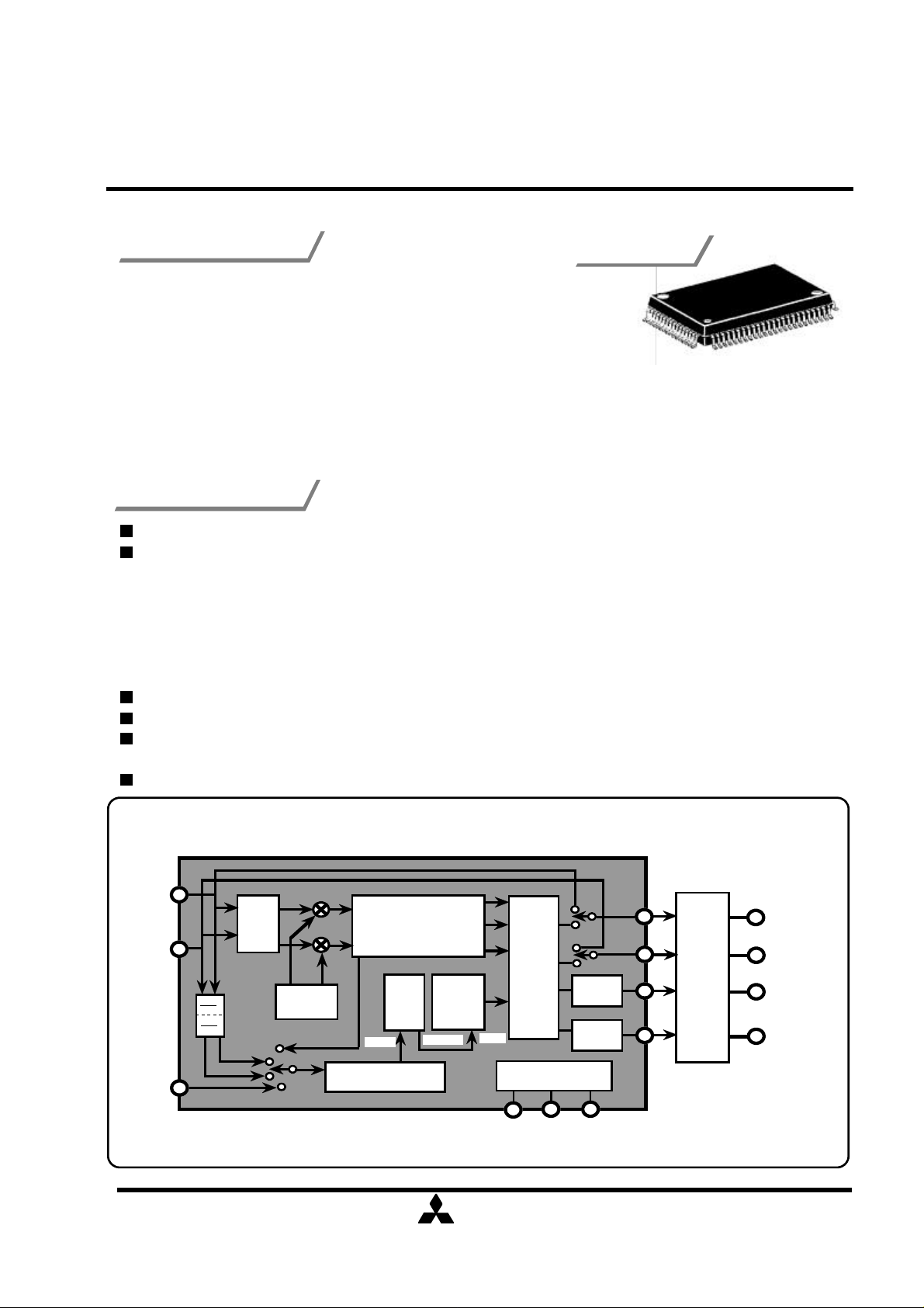
The M62465FP is a single chip LSI supporting the Dolby Prolgic
surround.This LSI contains all functions necessary for Dolby Pro Logic
surround. In addition,it has Digtal Space Surround functions
(Disco,Hall,Live mode etc.) and echo function for karaoke.
Note:Use of this LSI requires the license of Dolby Laboratories Licensing
Corporation
Dolby and the double-D symbol are trademarks of Dolby Laboratories
Licensing Corporation.San Francisco,CA94103-4813,USA.
This device available only to licensees of Dolby Lab.
Licensing and application information may be obtained from Dolby Lab.
Features
(Mode)
Outline 80P6N
0.8mm pich QFP
(20.0mm×14.0mm×2.8mm)
Upper compatible for M62460FP and less external parts than M62460FP.
Includes all functions requires for Dolby Pro Logic Surround.
•Adaptive Matrix.
•Noise Sequencer by digital noise source and switched capacitor filter.
•Center Mode Control(Wide/Normal/PHANTOM/OFF).
•Modified Dolby B Type Noise Reduction.
•4ch/3ch Stereo Selectable.
•Digital Delay: 15.4, 20, 28.6ms for Dolby Pro Logic Surround.
C/Sch Trimmer: 0 to -31dB/1dB Step.
Digital Space Surround Mode: Disco/Hall/Live mode and 5 delay time positions.
Digital Echo function for KARAOKE: (Short echo) Delay time=147.5ms, (Long echo) Delay
time=196.6ms.
BY-PASS Mode: Input signal through output.
System Configuration
Lch IN
Rch IN
MIC IN
Input
AutoBalance
S
Digital Noise
Digital Delay
Matrix
7kHz
LPF
Modified
Dolby
B-NR
( / )
1
L
R
C
Center/
operating
mode
S
MCU Interface
SCK
DATA
24
Center
Surround
REQ
L
R
C
S
Master
Volume
Control
Lch
Rch
CENTER
SURROUND
Page 2
ELECTRIC
MITSUBISHI
PRELIMINARY
Notice ; This is not a final specification.
some parametric limits are subject to change.
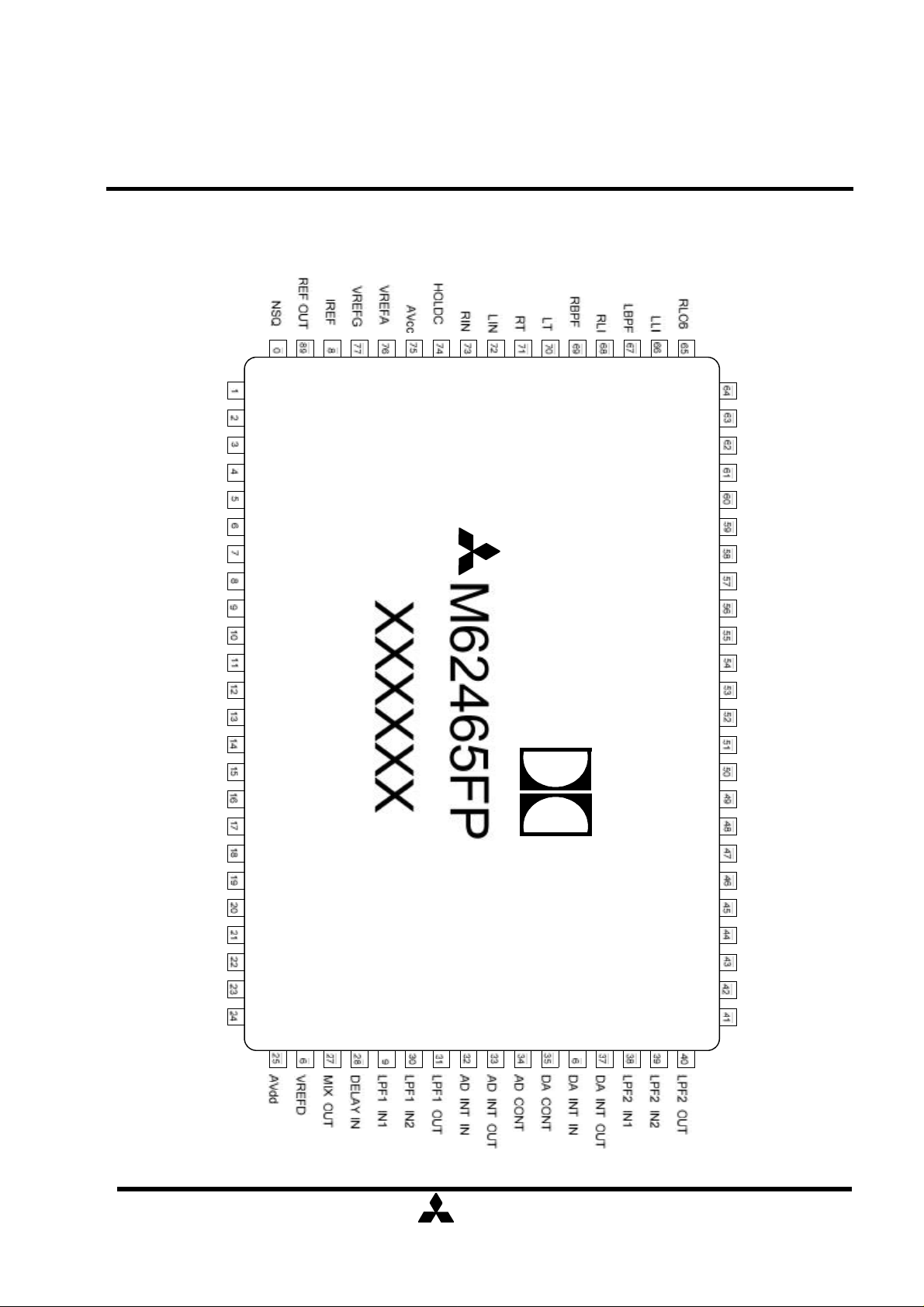
PIN CONFIGURATION
MITSUBISHI SOUND PROCESSORS
M62465FP
Dolby Pro Logic Surround
FILTER
LOUT
ROUT
CT
COUT
ST
SOUT
CMC
SMRO
SMRI
AGND
MIC IN
DVdd
TEST CNT
DATA
SCK
REQ
RLC8
RLC3
RLC7
RLC4
RLC1
RLC2
RLC5
PSC4
PSC1
PSC5
PSC2
PSC6
PSC3
DBC3
DBC2
DBC1
LPIN
LO1
LO2
LO3
XIN
XOUT
DVss
AVss
(Note) The function of pin No. 1,79,80 is different from that of M62460FP.
2
( / )
24
DBIN
S' OUT
FBIN SU
FBIN EC
DELAY SIG OUT
DELAY SIG IN
VOL OUT
Page 3
ELECTRIC
MITSUBISHI
PRELIMINARY
Digital NOISE
SEQUENCER
L+R L-R
COMBINNING
NETWORKS
IREF
VREF
SELECTOR1
MOS
SFB
MIX
MIC
L+R2L-R2SU
EC
1/2 Vcc
Notice ; This is not a final specification.
some parametric limits are subject to change.
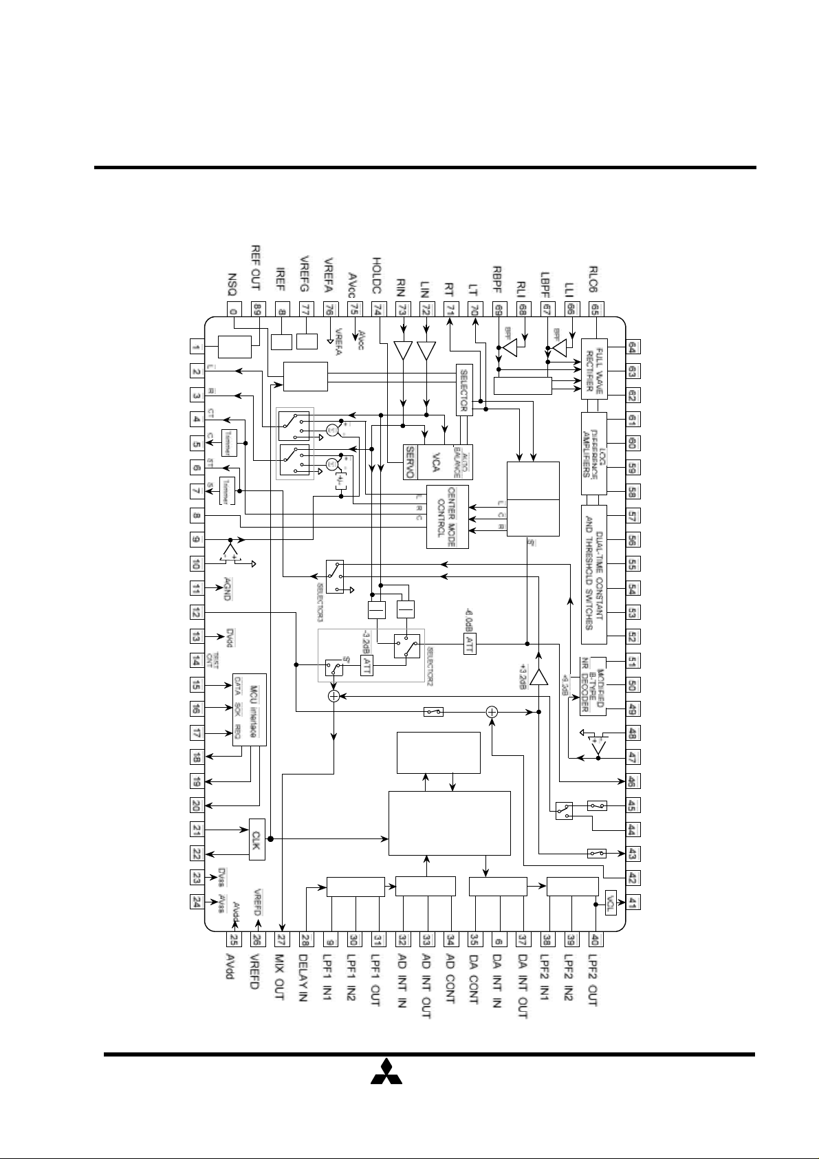
BLOCK DIAGRAM
MITSUBISHI SOUND PROCESSORS
M62465FP
Dolby Pro Logic Surround
FILTER
LOUT
ROUT
CT
COUT
ST
SOUT
CMC
SMRO
SMRI
AGND
MIC IN
DVdd
TEST CNT
DATA
SCK
REQ
LO1
LO2
16kSRAM
RLC8
RLC3
RLC7
RLC4
RLC1
RLC2
VCA
RLC5
PSC4
PSC1
PSC5
PSC2
PSC6
PSC3
DBC3
DBC2
DBC1
LPIN
DBIN
S' OUT
LO3
XIN
XOUT
DVss
AVss
FBIN SU
LPF
LOGIC
A/D
D/A
LPF
FBIN EC
DELAY SIG OUT
DELAY SIG IN
VOL OUT
(Note) The function of pin No. 1,79,80 is different from that of M62460FP.
( / )
3
24
Page 4
ELECTRIC
MITSUBISHI
PRELIMINARY
with external resistance.
when the operation
Discription of pin
Notice ; This is not a final specification.
some parametric limits are subject to change.
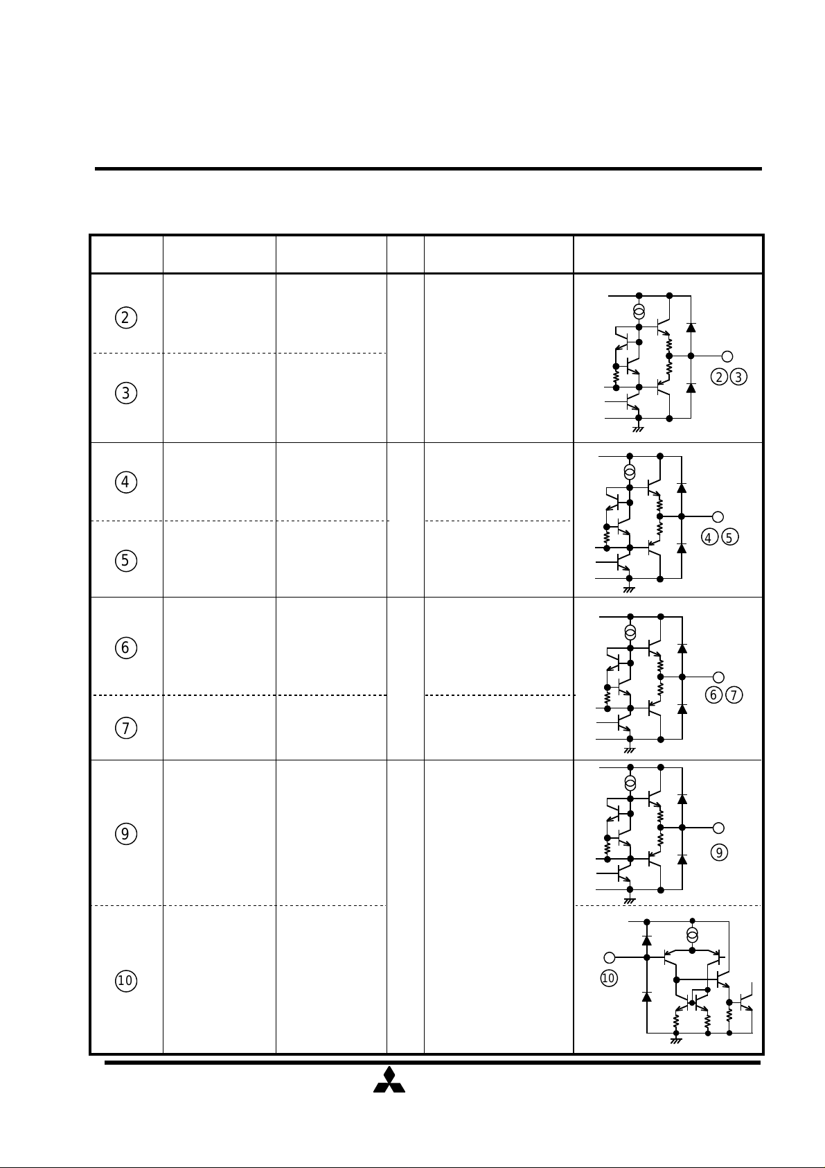
Discription of pin
MITSUBISHI SOUND PROCESSORS
M62465FP
Dolby Pro Logic Surround
No. Symbol
2
3
4
5
6
LOUT
ROUT
CT
COUT
ST Sch output
Funtion Equivalent circuit
Lch output
Rch output
Cch output
Cch output
Voltage
Direct output R-/ Lchannel when the operation
mode is BY-PASS.
4V
When the mode is 4channel,
they output Dolby prologic
R-/ L-channel signals.
No output any signals
mode is center mode is
OFF or set to PHANTOM.
4V
COUT is output from
C.Trimmer.
This pin output surrund
signals.Output is selected
from BNRout,Dout
No output signal when the
operation mode is
4V
3STEREO/MUTE.
Vcc
Vcc
Vcc
2 3
4 5
6
7
7
9
10
SOUT Sch output
SMRO
SMRI
amplifier
output
amplifier
input
SOUT is output from
S.Trimmer.
This is a amplifier to
control mixed level
4V
of surround output
( / )
4
24
Vcc
9
Vcc
10
Page 5
ELECTRIC
MITSUBISHI
PRELIMINARY
VREFD
with ECHO MODE
No.
Voltage
Discription of pin
Notice ; This is not a final specification.
some parametric limits are subject to change.
Symbol Funtion Equivalent circuit
MITSUBISHI SOUND PROCESSORS
M62465FP
Dolby Pro Logic Surround
Vcc
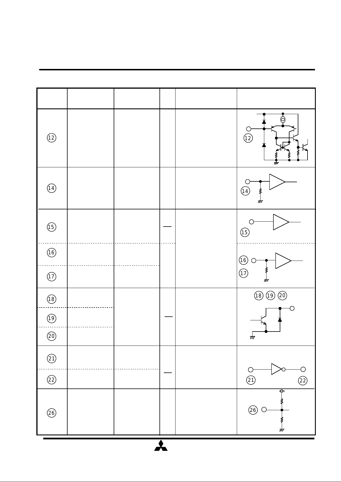
12 MIC IN MIC input 4V
14 TEST CNT
15
16
17
18
DATA
SCK
REQ
LO1
TEST
control
serial data
"DATA" input
serial data
"SCK" input
serial data
"REQ" input
0
Microphone input
Fixed to GND
input via serial data
from MCU.
0
15
16
17
14
12
18
19
buffer
buffer
buffer
20
19
20
21
22
26
LO2
LO3
XIN
XOUT
port output
Osillator input
Osillator output
reference output
Open collector output
pin (NPN Tr)
connect 4 - MHz
ceramic resonator
1/2 Vcc output.
2.5V
Connect a filter
capacitor.
( / )
5
24
21
22
26
Page 6
ELECTRIC
MITSUBISHI
PRELIMINARY
VOL OUT
input from mixing
with ECHO MODE
S',L+R,L-R and
from a mixing amplifier
with SURROUND MODE
Discription of pin
Voltage
Notice ; This is not a final specification.
some parametric limits are subject to change.
MITSUBISHI SOUND PROCESSORS
M62465FP
Dolby Pro Logic Surround
No.
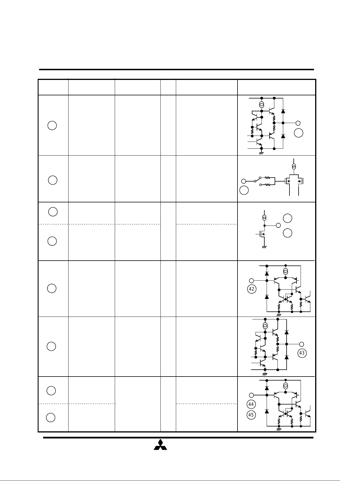
27
28
40
41
Symbol
MIX OUT
DELAY IN delay input
LPF2 OUT
Funtion
MIC output
delay signal
output
output of a
delay volum
Signal output precedent
to delay generator.
4V
that is S',L+R,L-R and
MIC output.
This is s delay input.
Please input by AC
2.5V
cuppring.
delay signal
output
2.5V
This is output of a
delay volum that
possible to control
+3dB to -∞.
Equivalent circuit
Vcc
27
28
40
41
42
43
44
45
DELAYSIG IN
DELAYSIG OUT
FBIN EC
FBIN SU
amplifier
Feedback signal
input
Delay signal input to
4V
a mixing amplifier
Delay signal output
4V
Feedback signal input
4V
Feedback signal input
Vcc
42
Vcc
43
Vcc
44
45
( / )
6
24
Page 7
ELECTRIC
MITSUBISHI
PRELIMINARY
Please pul-up to VREF
Autobalance
Negative input
with external resistances
Always outputs
No.
Voltage
Discription of pin
Autobalance output.
Autobalance
Notice ; This is not a final specification.
some parametric limits are subject to change.
Symbol Funtion Equivalent circuit
MITSUBISHI SOUND PROCESSORS
M62465FP
Dolby Pro Logic Surround
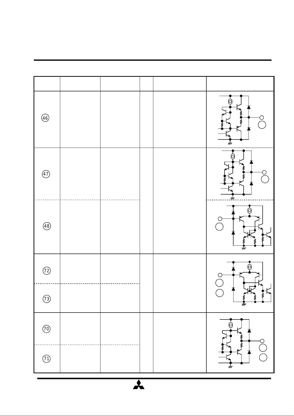
46
47
48 LPIN
S'OUT Sch output 4V
DBIN
LPF output
of LPF
Sorround channel
output precedent to
delay generator.
signals,irrespectiv of
the operation mode
(2-/3-/4-channel)
This amplifier
compornent 7KHz-LPF
4V
and capaciters.
LPF output is conected
to input of Modifide BNR.
Vcc
46
Vcc
47
Vcc
48
72
73
70
71
LIN
RIN
LT
RT
Lch input
Rch input
Lch output
Rch output
Input of Lch and Rch
that is non-inverted
input type.
4V
by external resistances
for DC bias.
4V
( / )
7
24
Vcc
72
73
Vcc
70
71
Page 8
ELECTRIC
MITSUBISHI
PRELIMINARY
Vcc
Vcc
VREFA
VREFG
Voltage is the fixed at 4V.
No.
Voltage
Discription of pin
reference voltage except
Auxiliary 1/2Vcc
Notice ; This is not a final specification.
some parametric limits are subject to change.
MITSUBISHI SOUND PROCESSORS
M62465FP
Dolby Pro Logic Surround
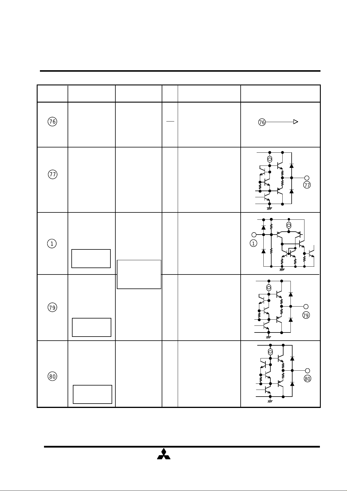
76
77
1
Symbol Funtion
reference
voltage
input
reference voltage
output
FILTER
New future of
M62465FP
1/2Vcc
It is a reference voltage
input terminal to each
circuit inside the IC.
Reference voltage output.
4V
The terminal which
make a 1/2Vcc voltage
1/2
by the resistance.
When it is used,a filter
capacitor is connected.
Equivalent circuit
76
Vcc
77
Vcc
1
79
80
REF OUT
New future of
M62465FP
NSQ
New future of
M62465FP
reference
generator.
1/2Vcc output
Noise sequencer
monitor
1/2Vcc voltage output.
It is used to change
1/2
4V.
Noise sequencer
4V
monitor output.
It is only for test.
Vcc
79
Vcc
80
( / )
8
24
Page 9

ELECTRIC
MITSUBISHI
PRELIMINARY
AMBIENT TEMPERATURE Ta (º
0.685
1.37
ABSOLUTE MAXIMUM RATINGS
θ
RECOMMENDED OPERATING CONDITION
Analog supply voltage
TERMAL DERATING
Notice ; This is not a final specification.
some parametric limits are subject to change.
MITSUBISHI SOUND PROCESSORS
M62465FP
Dolby Pro Logic Surround
Symbol Parameter Test conditions Limits Unit
Vcc
VDD
Pd
K
Topr
Tstg
Supply voltage
Power dissipation
Thermal derating
Operating temperature
Storage temperature
1.5
1.0
standard board
Ta≥25ºC
10.5
6.5
1.37
13.7
-20 to +75
-40 to +125
V
V
W
mW/ºC
ºC
ºC
Symbol
Vcc
VDD
fck
• board size
• board thickness
• board material
• copper pattern
Parameter
Digital supply voltage
OSC clock
0.5
0
25 50 75 100 125
0
Standard board
copper thickness
copper size
Conditions
150
C)
70mm×70mm
1.6mm
glass epoxy
18µm
0.25mm(width)
30mm(length / lead)
Min
8.0
Ratings
Typ
9.0
5.0 5.54.5
4
Max
10.0
Unit
V
V
MHz
( / )
9
24
Page 10

ELECTRIC
MITSUBISHI
PRELIMINARY
ELECTRICAL CHARACTERRISTICS (DECODER)
Vref
V
Vno
VGNR
Vin=0dBd,f=1.0kHz
Vin=-15dBd,f=1.4kHz
Vin=-20dBd,f=1.4kHz
Vin=-40dBd,f=5.0kHz
Vin=0dBd,f=1kHz
C,S ch Trimmer
ATT
Maximum attenuation
Vin=0dBd,f=1kHz
ATT
Circuit Current
Quiescent
Circuit Current
Quiescent
Quiescent
Input Auto Balance
Adaptive Matrix
Reference Voltage
Trimmer step
Peak Noise
Vnop
Peak Noise
Notice ; This is not a final specification.
some parametric limits are subject to change.
MITSUBISHI SOUND PROCESSORS
M62465FP
Dolby Pro Logic Surround
Vcc=9V,VDD=5V 0dB Reference=300mVrms/1KHz at C-OUT unless otherwise noted.(Cch Trimmer=0dB)
Symbol Parameter
Conditions
Min
Limits
Typ
Max
Unit
Overall
Icc
IDD
3.5
25
25
4.0
50
50
4.5
mA
mA
CPR
CER
∆VoL
MR
HRAM L, R, C, S' out
THDAM
SNAM
NopAM
Noise Sequencer
∆Vno
Modified B type Noise Reduction
DEC1
DEC2
DEC3
DEC4
THDNR
HRNR THD=1%
SNNR
NoPNR
Capture Range
Error Correction
Output Level Accuracy
relative to C ch
Matrix Rejection relative
Headroom
Total Harmonic Distortion
Signal to Noise Ratio
(0dBd Reference is input at NR-IN when adjust to 0dB (300mVrms/100Hz) at S out.
Output Noise Level
Output Level Accuracy
relative to C ch
Output Noise peak measurement time=6sec
Voltage Gain
Decode Responce 1
Decode Responce 2
Decode Responce 3
Decode Responce 4
Total Harmonic Distortion
Headroom
Signal to Noise Ratio
L, R, S'ch out
L, R, C, S'ch out
L, R, C, S'ch out
L, Rch out 2ch mode
Rg=0Ω,weighted CCIR/AMR
L, Rch out 2ch mode
measurement time
=40msec
L, R, S'ch out
Vin=0dBd,f=100Hz
Rg=0Ω, weighted CCIR/AMR
measurement time=40msec
4ch mode
4ch mode
4ch mode
2ch mode
±5
±4
-0.5
25
15
75
95
0
40
17
0.05
0.002
80
100
0.5
0.2
0.05
±0.3
±0.3
-15
-0.5 0.5
-12.5
0
-10
±550
9.2
-1.6
-3.0
-4.9
-6.8
15
73
-0.1
-1.5
-3.4
-5.3
0.0
7
17
78
1.4
0
-1.9
-3.8
0.3
±0.3
dB
dB
dB
dB
dB
%
dB
mV0-p
dB
dB
mV0-p
dB
dB
%
dB
dB
mV0-p
-12dB
attenuation level:-12dB Digital Input=-12
max
Digital Input=-31
TS
Surround (L+R,L-R)
THDSU
SNSU
Total Harmonic Distortion
Signal to Noise Ratio
<MIXOUT>
Rg=0Ω, weighted CCIR/AMR
( / )
10
24
-14
-37 dB
0.6
-12
-31 -25
1.0
0.05
85
90
-10
1.4
0.2
dB
dB
%
dB
Page 11

ELECTRIC
MITSUBISHI
PRELIMINARY
Vrms
Vomax
ATTmax
(Ta=25•
C
,Vcc=9V,VDD=5V,Vin=200mVrms
,
fck=4MHz unless otherwise noted)
ELECTRICAL CHARACTERRISTICS (DIGITAL DELAY)
Notice ; This is not a final specification.
some parametric limits are subject to change.
MITSUBISHI SOUND PROCESSORS
M62465FP
Dolby Pro Logic Surround
Symbol
Digital Delay
Td
Gv
THD
Maximum output voltage 30kHz LPF,THD=10%
No
Delay Volume
Gv
Maximum attenuation
Parameter
Delay time
Input-output gain
Output distortion
Output noise voltage
(VOL OUT)
Input-output gain
Conditions
See Delay time contorol (15/24)
fordelay time setting.
Td=15.4ms
Td=20.0ms
Td=28.6ms
30kHz LPF
Rg=620Ω,
Vi=0mVrms,
IHF-A
Volume max
Delay off mode,Volume min,IHF-A
Td=41.0ms
Td=49.2ms
Td=147.5ms
Td=196.6ms
Td=15.4ms
Td=20.0ms
Td=28.6ms
Td=41.0ms
Td=49.2ms
Td=147.5ms
Td=196.6ms
Limits
Min Typ
12.4
17.0
25.6
38.0
186.6
0.7
15.4
20.0
28.6
41.0
49.2
147.5
196.6
0
0.3
0.3
0.5
0.6
0.7
1.5
2.0
1.0
-92
-92
-92
-90
-90
-82
-77
3
-70
Max
18.4
23.0
31.6
44.0
52.246.2
157.5137.5
206.6
3.0-3.0
0.6
0.6
1.0
1.2
1.4
3.0
4.0
-80
-80
-80
-75
-75
-67
-62
60
-60
Unit
ms
dB
%
dBv
dB
dB
( / )
11
24
Page 12

ELECTRIC
MITSUBISHI
PRELIMINARY
TEST CIRCUIT
Notice ; This is not a final specification.
some parametric limits are subject to change.
MITSUBISHI SOUND PROCESSORS
M62465FP
Dolby Pro Logic Surround
( / )
12
24
Page 13

ELECTRIC
MITSUBISHI
PRELIMINARY
DIGITAL CONTROL SPECIFICATIONS
ADDRESS
ADD/SUB
CENTER MODE
Notice ; This is not a final specification.
some parametric limits are subject to change.
(1)DATA TIMING
REQ
t7
SCK
t2 t3
t1
t5 t6
MITSUBISHI SOUND PROCESSORS
M62465FP
Dolby Pro Logic Surround
t8
t4
4
1
DATA
(note1) SCK is diseble when REQ is high
(Note2)REQ must turn to high after SCK pulse turn to high.
0
Symbol
t1
t2
t3
t4
t5
t6
t7
t8
SCK clock duration
SCK "H" pulse width
SCK "L" pulse width
REQ hold time
DATA setup time
DATA hold time
SCK setup time
REQ "H" pulse width
2 3
Name
5 6
7
8
10
9 11
Min Typ Max Unit
2
0.8
0.8
1.6
0.8
0.8
0.8
1.6
µs
µs
µs
µs
µs
µs
µs
µs
(2)DATA FORMAT
BIT 1 BIT 2 BIT 3 BIT 4 BIT 5BIT 0 BIT 6 BIT 7
NOISE SEQ
SELECTOR2 SELECTOR3
Cch. TRIMMER
S1 S2 S3 V1 V2 V3
Serial Data Format
DATA
SELECTOR1
MIX
LO1
LO2
Sch. TRIMMER 1 0
V4
13
( / )
24
BIT 8
BIT 9 BIT 10BIT 11
No use
LO3
SFB MOS MIC
No use
0 0
0 1
1 1
Page 14

ELECTRIC
MITSUBISHI
PRELIMINARY
Volume code
ATT(dB)
ATT(dB)
♦
♦
ADD/SUB
ADD
(LO1)
(LO2)
(LO3)
Notice ; This is not a final specification.
some parametric limits are subject to change.
(3)DECODER
ADDRESS(BIT10,11)=0,0
MITSUBISHI SOUND PROCESSORS
M62465FP
Dolby Pro Logic Surround
NOISE SEQ
mode
SUB
ADDRESS(BIT10,11)=0,1
LO(LOGIC DATA OUT)
OUTPUT DATA "L"
OUTPUT DATA "H"
BIT0
0
1
SELECTOR2
mode
S'
L+R
L-R
MIC
mode
BIT0 BIT1
0
0
1
1
mode
OFF
ON
0
1
0
1
Open Collector
BIT5
BIT1
0
1
0
1
• ADDRESS(BIT10,11)=1,0
mode
BNR OUT
D OUT
3STEREO/MUTE
BIT6
0
1
BIT2 BIT3
L
C
R
S
SELECTOR3
mode
BIT7
0
1
0
0
1
1
0
1
0
1
BIT2
0 0
0
1
1
SELECTOR1
mode
PRO LOGIC
BY-PASS
OTHER SUR
L/R MUTE
BIT3
1
0
1
BIT4 BIT5
0
0
1
1
BIT4(MIX)
0
1
CENTER MODE
mode
0
WIDE
1
NORMAL
0
PHANTOM
OFF
1
DELAY MIX SWITCH
DMIXSW
OFF
ON
Remarks
Mixing OFF
Mixing ON
BIT6 BIT7
0
0
0
1
0
1
1
1
DATA
0
1
±0
–1
–2
–3
–4
–5
–6
–7
–8
–9
–10
–11
–12
–13
–14
–15
Cch. TRIMMER
BIT0 BIT1 BIT4
±0dB
–1dB
BIT0(5) BIT1(6) BIT4(9)
0 0 0 0 0
1 0 0 0 0
0 1 0 0 0
1 1 0 0 0
0 0 1 0 0
1 0 1 0 0
0 1 1 0 0
1 1 1 0 0
0 0 0 1 0
1 0 0 1 0
0 1 0 1 0
1 1 0 1 0
0 0 1 1
1 0 1 1 0
0 1 1 1 0
1 1 1 1 0
±0dB ±0dB
–2dB –4dB –8dB –16dB
BIT2 BIT3
±0dB
BIT2(7) BIT3(8)
±0dB
C(S)ch. TRIMMER
0
–16
–17
–18
–19
–20
–21
–22
–23
–24
–25
–26
–27
–28
–29
–30
–31
Sch. TRIMMER
DATA
0
1
BIT0(5) BIT1(6)
BIT5 BIT6 BIT9
±0dB
–1dB –2dB –4dB –8dB –16dB
0 0 0 0 1
1 0 0 0 1
0 1 0 0 1
1 1 0 0 1
0 0 1 0 1
1 0 1 0 1
0 1 1 0 1
1 1 1 0 1
0 0 0 1 1
1 0 0 1 1
0 1 0 1 1
1 1 0 1 1
0 0 1 1 1
1 0 1 1 1
0 1 1 1 1
1 1 1 1 1
±0dB ±0dB
BIT2(7) BIT3(8)
BIT7 BIT8
±0dB
BIT4(9)
±0dB
( / )
14
24
Page 15

ELECTRIC
MITSUBISHI
PRELIMINARY
ADDRESS(BIT10,11)=1,1
(Sampling frequency)
(Cut-off frequency)
VOLUME CONTROL
∞–∞–∞–∞–∞
Notice ; This is not a final specification.
some parametric limits are subject to change.
(4)DELAY
MITSUBISHI SOUND PROCESSORS
M62465FP
Dolby Pro Logic Surround
DELAY TIME CONTROL
BIT0
(S1)
BIT7(SFB)
(In surround mode only)
BIT8(MOS)
BIT1
(S2)
0
0 0 1
0 1 0
0 1 1
1 0 0
1 0 1
1 1 0
1 1 1
BIT2
(S3)
0 0
FEEDBACK SWITCH
SFB SW
0
1
OFF
ON
MODE SELECTOR
MODESEL
0
1
SU line
EC line
DELAY TIME
ms
15.4
( 1MHz )
20.0
ms
( 667kHz )
28.6
ms
( 500kHz )
41.0
ms
( 400kHz )
49.2
ms
( 333kHz )
147.5
ms
( 111.1kHz )
196.6
ms
( 83.3kHz )
Delay off mode (clock off)
Remarks
Feedback OFF
Feedback ON
Delay LPF
7.0kHz
3.0kHz
BIT3
(V1)
1
1
1
1
1
1
1
1
0
0
0
0
0
0
0
0
BIT4
(V2) (V3)
BIT5
1 1
1
1
1
0
0
0
0
1
1
1
1
0
0
0
0
BIT6
(V4)
1
0
0
1
1
0 1
0 0
1 1
1 0
0 1
0 0
1 1
1 0
0 1
0 0
VOL attenuation
1
0
1
0
1
0
+3dB
0dB
-2dB
-3dB
-4dB
-6dB
-8dB
-9dB
-10dB
-12dB
-15dB
–
MICROPHONE MIXING SWITCH
BIT9(MIC)
0
1
MICMIXSW
OFF
ON
Remarks
Mic mixing OFF
Mic mixing ON
(Note1)Settings in power up
When power is turned on, data is setting in under table by power on reset circuit.
DECODER
Mode Settings Mode Settings
ADD/SUB
NOISE SEQ
SELECTOR1
CENTER MODE
SELECTOR2
SELECTOR3
LO(LOGIC OUT)
Cch.TRIMMER
Sch.TRIMMER
ADD
OFF
PRO LOGIC
WIDE
S'
BNR OUT
"L"
0dB, ATT(-)
0dB, ATT(-)
DELAY TIME CONTROL
VOLUME CONTROL
FEEDBACK SWITCH
MODE SELECTOR
DELAY MIX SWITCH
MICROPHONE MIXING SWITCH
DELAY
20.0ms
–∞
OFF
SU line
OFF
OFF
(Note2)
The digital the noise sequencer stop when the clock is off.
( / )
15
24
Page 16

ELECTRIC
MITSUBISHI
PRELIMINARY
Notice ; This is not a final specification.
some parametric limits are subject to change.
MITSUBISHI SOUND PROCESSORS
M62465FP
Dolby Pro Logic Surround
( / )
16
24
Page 17

ELECTRIC
MITSUBISHI
PRELIMINARY
SEQUENCER
R
C
L
CONTROL
(L-R)2(L+R)
Echo filter
Surround filter
Modifide BNR
7kHz
C.Trimmer
S.Trimmer
Delay Mix SW
SU
EC
SELECTOR1
(0 to -31dB)
(0 to -31dB)
SELECTOR3
OUT
DOUT
SELECTOR2
MIC
ADD/SUB
MIX
+
-
+
VREFA
MOS
C.Trimmer
S.Trimmer
A simple noise sequencer circuit for ajustment of
Block name
Function
LPF
Notice ; This is not a final specification.
some parametric limits are subject to change.
FUNCTION
Block Diagram
NOISE
Lin
Rin
S'
2
MIC
ADAPTIVE
MATRIX
MIC
CENTER
MODE
WIDE
NORMAL
PHANTOM
OFF
MITSUBISHI SOUND PROCESSORS
M62465FP
Dolby Pro Logic Surround
BY-PASS
PLOLOGIC
OTHER
MUTE
3STEREO/MUTE
BNR
Lout
Rout
Cout
CT
Sout
Dout
AVcc
(+9V)
AGND
INPUT
BALANCE
NOISE
SEQUENCER
ADAPTIVE
MATRIX
Digital Deley
MCU Interface
VOL
VDD
AVDD
(+5V)
4MHz
DATASCKREQ
Revises a level error between the input Lch and Rch
for optimum decorder performance.
output level.
Contineuously analyze the two-channel matrixed
audio input to determine the direction and relative
magnitude of encoded soundfield.
LO1
LO2
LO3
GND
CENTER MODE
CONTROL
Possible to select 4 - center mode position.
(WIDE,NORMAL,PHANTOM,OFF)
This is the level ajustment volum of Cch and Sch.
( 0 to -30 dB : 1dB/step )
( / )
17
24
Page 18

ELECTRIC
MITSUBISHI
PRELIMINARY
Function
while reducing noise and certain crosstalk signals in a
This is a switch to mix miclophone signal to a main
This is a switch to select output or not a mixed signal
Block name
Notice ; This is not a final specification.
some parametric limits are subject to change.
This block restores the signal to its original spectrum
Modifide BNR
final stage of the surround chain.
Select a positive phase signal or a negative phase
ADD/SUB
SELECTOR1
signal with DIGITAL SPACE SURROUND MODE.
This is a selective switch to select the output signal
of Lout and Rout from BY-PASS,PRO LOGIC,OTHER
SUR and MUTE .
MITSUBISHI SOUND PROCESSORS
M62465FP
Dolby Pro Logic Surround
SELECTOR2
SELECTOR3
SELECTOR4
Digital Deley
FEEDBACK
MODE SEL(MOS)
This is a selective switch to select the output signal
of Sout from S',L+R,L-R and MIC.
This is a selective switch to select the output signal
of Sout from BNRout,Dout and 3STEREO/MUTE.
This is a switch to connect a simple noise
sequencer output to ADAPTIVE MATRIX stage for
level ajust-ment.
Make 7 kinds of delay signal s.(15.4msec to 196.6msec)
The delay function and CLK signal stop at the time
of DELAY OFF MODE.
This mode is for suppress bad effect of digital noize.
This is a switch to select feedback mode(ON/OFF)
for SURROUND MODE .
This is a switch to select a feedback signal from
surround signal and echo signal.
VOL
MIC MIX
(12-step)
signal (Lch,Rch).
Delay Mix SW
to DOUT pin.
( / )
Control the ATT level of delay signal from 3dB to -∞
18
24
Page 19

ELECTRIC
MITSUBISHI
PRELIMINARY
Lout,Rout,Cout
ADAPTIVE
ADAPTIVE
ATT
Sout
Notice ; This is not a final specification.
some parametric limits are subject to change.
LEVEL DIAGRAM
• Dolby Pro Logic mode
MITSUBISHI SOUND PROCESSORS
M62465FP
Dolby Pro Logic Surround
Gv
GND
Lin
Rin
VCC=9V
Vref=4V
Gv
Vcc=9V
3dB
INPUT
BALANCE
MATRIX
3dB
0dB(300mV)
S'
-6dB
0dB(300mV)
-3.2dB
9.2dB
VDD=5V
Vref=2.5V
Digital
Delay
0dB(300mV)
Vcc=9V
Vref=4V
Modified
BNR
SOUT
GND
Gv
Vcc=9V
GND
Lin
Rin
Vref=4V
Vref=4V
INPUT
BALANCE
MATRIX
0dB(300mV)
( / )
19
CENTER
MODE
CONTROL
24
Cout
Lout,Rout
Cout
Lout
Rout
Page 20

ELECTRIC
MITSUBISHI
PRELIMINARY
ATT
ADAPTIVE
Sout
Lout,Rout
Notice ; This is not a final specification.
some parametric limits are subject to change.
• Digital Space Surround mode
MITSUBISHI SOUND PROCESSORS
M62465FP
Dolby Pro Logic Surround
Gv
GND
Lin
Rin
Vref=4V
Gv
VCC=9V
0dB(300mV)
L+R
2
L-R
2
SELECTOR2
-3.2dB
0dB(300mV)
3dB
VDD=5V
Vref=2.5V
Digital
Delay
0dB(300mV)
Vcc=9V
Vref=4V
SOUT
SELECTOR3
Vcc=9V
GND
Lin
Rin
Vref=4V
INPUT
BALANCE
MATRIX
( / )
24
20
CENTER
MODE
CONTROL
Lout,Rout
Lout
Rout
Page 21

ELECTRIC
MITSUBISHI
PRELIMINARY
Notice ; This is not a final specification.
some parametric limits are subject to change.
AUTO MUTE FUNCTION
The IC carries out auto mute function at the time of powerring up, delay time
setting change, and cancelling delay off mode, in order to suppress shock noise
that the digital delay may produce.
• At power up
* Transient noise common with power up occurs.
MITSUBISHI SOUND PROCESSORS
M62465FP
Dolby Pro Logic Surround
RESET TIME
Power up
• At delay time setting change
• At canceling delay off mode
Freed from
resettung
Delay signal before change Delay signal after change
Instruction
to change
delay time
MUTE TIME
Freed from muting
Internal delay time
setting
MUTE TIME
Freed from muting
Internal delay
time change
MUTE TIME
Canceling delay
off mode
Mute time changes depending on set (or preset) delay time.
DELAY TIME
15.4 to 49.2 ms
147.5 ,196.6 ms
( / )
21
MUTE TIME
24
Freed from muting
123 ms
492 ms
Page 22

ELECTRIC
MITSUBISHI
PRELIMINARY
Notice ; This is not a final specification.
some parametric limits are subject to change.
MITSUBISHI SOUND PROCESSORS
M62465FP
Dolby Pro Logic Surround
( / )
22
24
(Note)
It's recommended to remove these external
parts of M62460FP.
(These external parts don't affect the funtion of
M62465FP actually.)
Page 23

ELECTRIC
MITSUBISHI
PRELIMINARY
Notice ; This is not a final specification.
some parametric limits are subject to change.
MITSUBISHI SOUND PROCESSORS
M62465FP
Dolby Pro Logic Surround
( / )
23
24
Page 24

ELECTRIC
MITSUBISHI
PRELIMINARY
OPTIONAL PARTS LIST
Values
Values
ΩKΩ
Ω
ΩKΩ
Vol
Vol
ΩKΩ
Ω
Ω
Ω
Ω
Ω
Ω
Ω
Ω
Ω
Ω
Ω
Ω
Notice ; This is not a final specification.
some parametric limits are subject to change.
MITSUBISHI SOUND PROCESSORS
M62465FP
Dolby Pro Logic Surround
Parts No.
C1
C2
C3
C5
C6
C8
C12
C21
C22
C25
C26
C27
C29
C30
C32
C34
C35
C36
C38
C39
C40
C41
C44
C45
C47
C48
C49
C50
C51
C52
C53
C54
C55
C56
C57
C58
C59
C60
C61
C62
C63
C64
Unit
47
10
10
10
10
0.1
1
27
27
100
22
1
0.01
0.0018
0.068
0.1
0.1
0.068
0.01
0.0018
0.1
0.1
1200
470
680
0.1
0.0056
0.047
0.68
0.22
0.22
4.7
4.7
0.22
0.22
0.1
0.047
0.047
0.1
0.1 20%
0.022
0.022
µF
µF
µF
µF
µF
µF
µF
pF
pF
µF
µF
µF
µF
µF
µF
µF
µF
µF
µF
µF
µF
µF
pF
pF
pF
µF
µF
µF
µF
µF
µF
µF
µF
µF
µF
µF
µF
µF
µF
µF
µF
µF
Tol.
10%
5%
5%
5%
5%
5%
5%
5%
5%
5%
10%
5%
5%
10%
10%
10%
20%
20%
10%
10%
20%
5%
5%
20%
5%
5%
Parts No.
C65
C66
C67
C68
C69
C70
C71
C72
C73
C74
C75
C77
C79
R6
R9
R21
R22
RA44
RA45
R44
R45
R47
R48
R51
R66
RA66
R67
R68
RA68
R69
R72
R73
R74
R78
Unit
0.1
680
0.1 µF 5%
680
0.1 µF 5%
0.1 µF 5%
0.1 µF 5%
10
10
22
100 µF
220
220 µF
10
20
1
1
51
51
24
24
330
47
15
7.5
47
15
7.5
22
22
4.7
100
µF
pF
pF
µF
µF
µF 20%
µF
K
M
K
K
K
K
K
K
K
K
K
K
K
K
M
K
Tol.
20%
5%
5%
5%
5%
10%
5%
5%
5%
5%
5%
5%
10%
1%
( / )
24
24
 Loading...