

Page 1
MITSUBISHI SOUND PROCESSOR ICs
for
spectrum analyzer displays.
• Single 5V power supply.
CD radio cassette players , mini-component stereo systems, car stereos
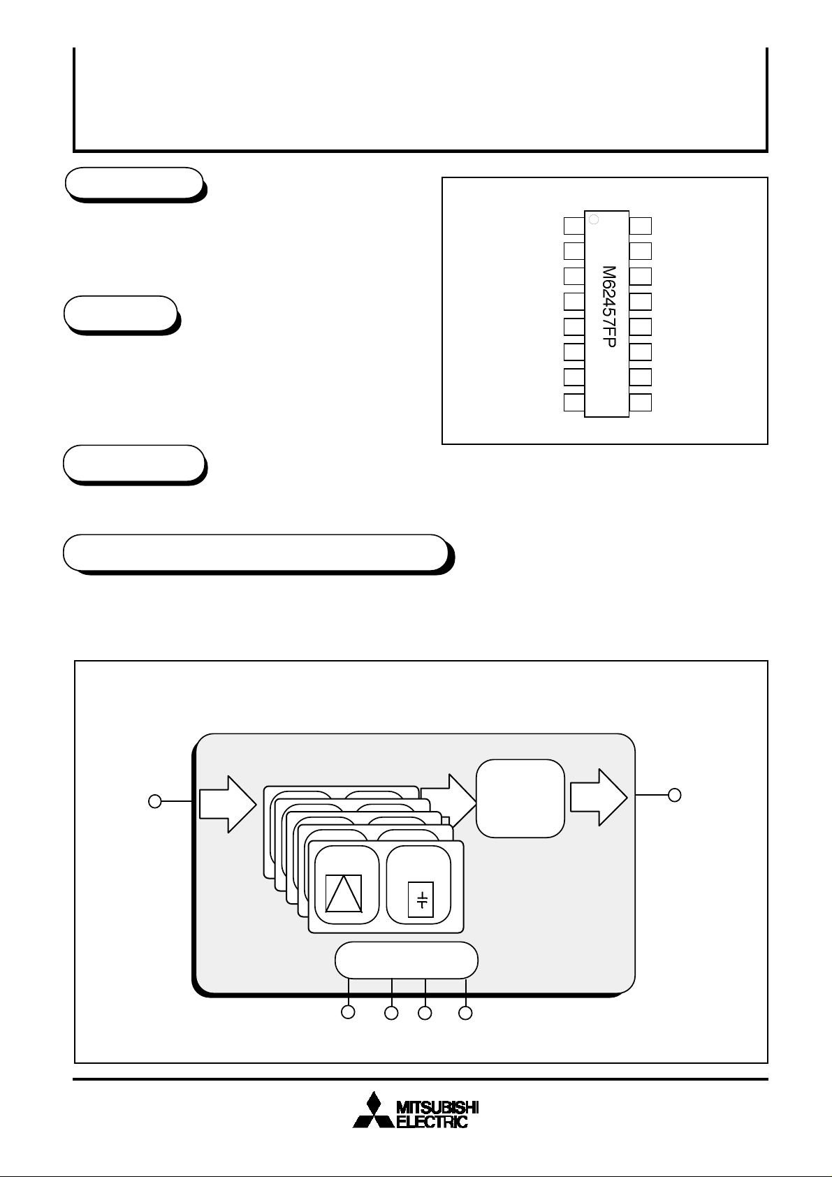
M62457FP
Peak hold IC for 5 band spectrum analayzer displays
DESCRIPTION
The M62457FP is 5 band peak hold ICs that use
microprocessor time division to produce serial output
FEATURES
• 5 band peak hold elements for spectrum analyzer
displays.
• Discharg time constant circuit for each band is on the
chip.
APPLICATION
RECOMMENDED OPERATING CONDITIONS
Supply voltage range • • • • 4.5 to 6.5V
Rated supply voltage • • • • 5.0V
PIN CONFIGURATION (TOP VIEW)
Vcc/2
VREF
IREF
DIFOUT
COUT
CNF
AOUT
ANF
1
2
3
4
5
6
7
16
15
14
13
12
11
10
98
GND2
PHOUT
GND1
ENB
SELC
SELB
SELA
Vcc
Outline 16P2N-A
SYSTEM BLOCK DIAGRAM
Audio
signal
BPF5
SELA
µ-com
interfac
SELB
PeaK
Hold5
SELC
SELECTOR
Peak
Hold
output
ENB
1
( / 12 )
Page 2
MITSUBISHI SOUND PROCESSOR ICs
Peak hold IC for 5 band spectrum analayzer displays
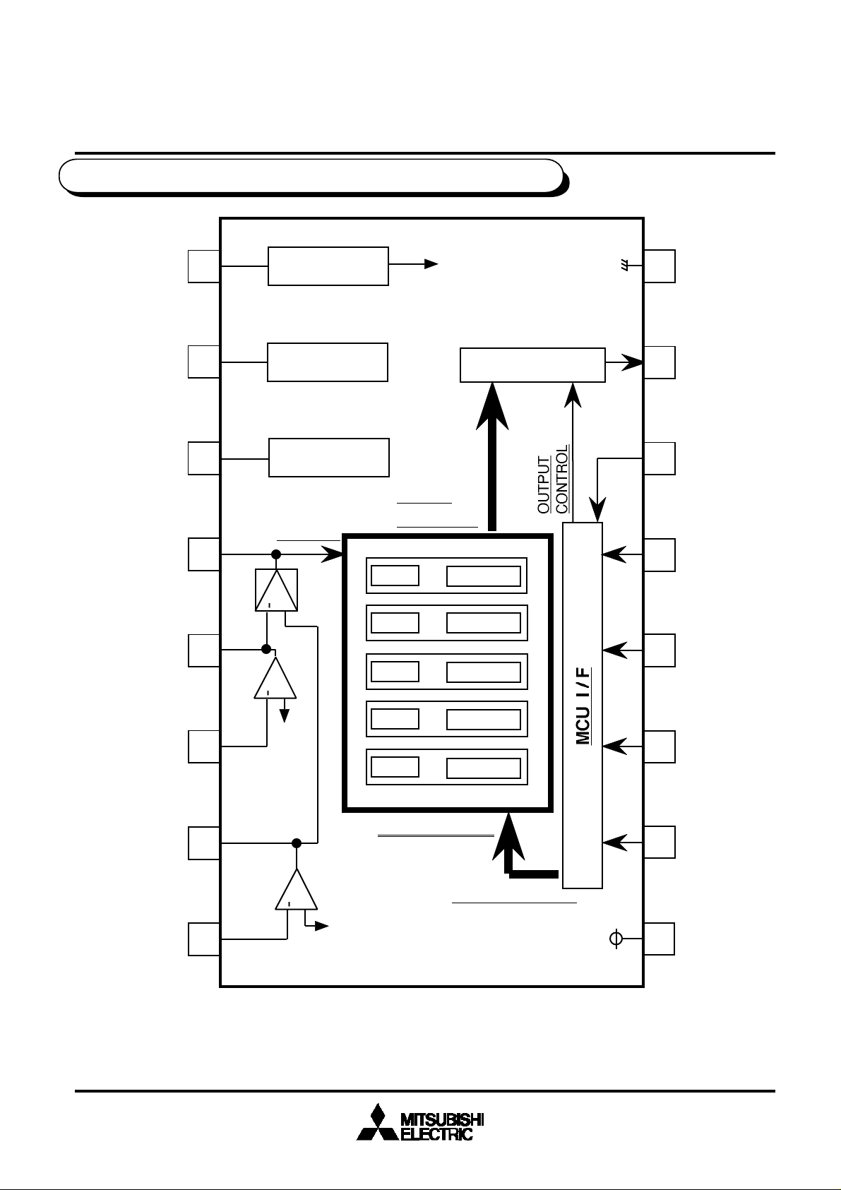
PIN CONFIGURATION AND IC INTERNAL BLOCK DIAGRAM
M62457FP
Vcc/2
VREF
IREF
DIFOUT
COUT
1
2
3
4
5
Amp-C
Vcc/2 Gen.
V REF Gen.
(VCC X 0.3 )
I REF Gen.
BPF IN
Amp-D
+
+
HOLD
OUTPUT
BPF 1
BPF 2
BPF 3
SELECTEOR
P.HOLD
P.HOLD
P.HOLD
TEST
16
15
14
13
12
GND2
PHOUT
GND1
ENB
SELC
CNF
AOUT
ANF
BPF 4
6
BPF 5
P.HOLD
P.HOLD
11
SELB
<PEAK HOLD>
SELA
7
Amp-A
+
HOLD C RESET
8
10
9
Vcc
(Notes)f1=105Hz,f2=340Hz,f3=1KHz,f4=3.4KHz,f5=10.5KHz
(The value is the design value)
( / 12 )
2
Page 3

MITSUBISHI SOUND PROCESSOR ICs
M62457FP
Peak hold IC for 5 band spectrum analayzer displays
Functional description
(1) Audio signal passes Amp-a and Amp-d, and it is input into BPF/peak hold
circuit for spectrum analyzer.
Basic use examples,the last output signal is input into A/D of microprocessor.
Howevwe VCC,GND of analog series had better be common with VCC,GND of
maicroprocessor. THe maicroprocessor does groundisolation to analog series.
Amp-C is the input amplifier to reject common-mode signal (noise),
it utilizes effect of common-mode rejection of Amp-D.
(2) BPF/peak hold circuit is setting of 5 band spectrum analyzer
< center frequency >
f1=105Hz
f2=340Hz
f3=1KHz
f4=3.4KHz
f5=10.5KHz
(The value is the design value)
Center frequency and Q of BPF is done general setting of like next.
w0=gm/C
gm:matual condactance of inside amplifier circuit
(It depends on outside resistor of Pin.No.3)
C:inside capacitor
Q=(R1+R2)/R1 ; it is fixed by inside resistor ratio.
(The design value is 3.5)
(3) The hold capasitor of peak hold circuit use inside capasitor.
When a selection of hold output is over the reset signal of hold value,
The reset signal is made automatically.
(Discharge pulse : -3dBtyp. output value fall)
(4) Output voltage of peak hold circuit is Vcc/2(Pin.No1)
When it is selected by the optput select circuit, it is converted into the voltage
of GND standard and outputs it in PHout (Pin.No.15).
3
( / 12 )
Page 4
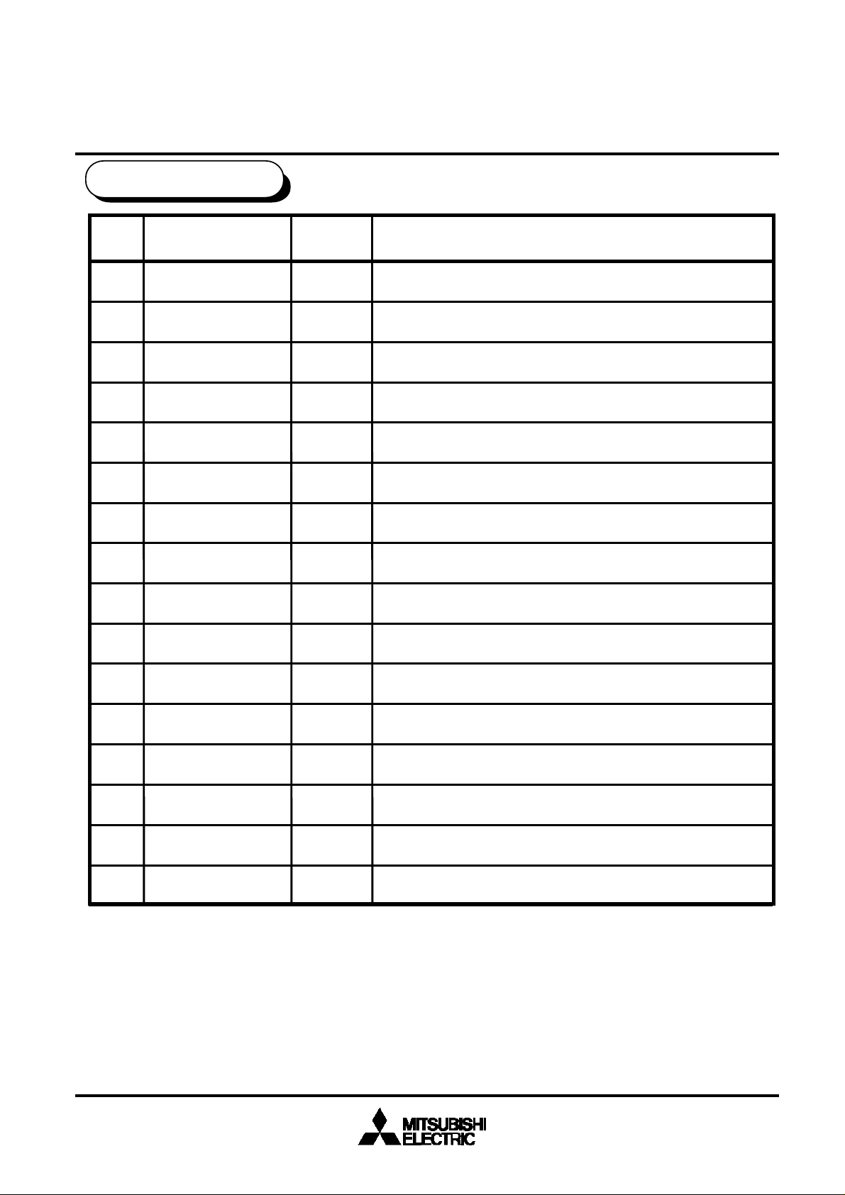
PIN DESCRIPTION 1
MITSUBISHI SOUND PROCESSOR ICs
M62457FP
Peak hold IC for 5 band spectrum analayzer displays
PIN No.
1
2
3
4
5
6
7
8
9
10
Name
Vcc / 2
VREF
IREF
DIFOPUT
COUT
CNF
AOUT
ANF
Vcc
SELA
I / O Function
I
I
I
O
O
I
O
I
I
I
1/2Vcc supply terminal
0.3Vcc supply terminal
BPF center frequency setting current terminal
Output of amplifier (BPF input signal )
Output of amplifier for analog COM series
Inverted input of amplifier for analog COM series
Output of amplifier for analog signal series
Inverted input of amplifier for analog signal series
System supply terminal
Output setting control terminal A ( logic input )
11
12
13
14
15
16
SELB
SELC
ENB
GND1
PHOUT
GND2
O
I
I
I
I
I
Output setting control terminal B ( logic input )
Output setting control terminal C ( logic input )
Output setting control enble terminal ( logic input )
Ground1 ( it is assumed in the voltage same as PIN16 )
Peak hold outout terminal
Ground2 ( signal series )
( / 12 )
4
Page 5

PIN DESCRIPTION 2
MITSUBISHI SOUND PROCESSOR ICs
M62457FP
Peak hold IC for 5 band spectrum analayzer displays
PIN No.
1
2
3
4
5
6
7
Name
Vcc / 2
VREF
IREF
DIFOPUT
COUT
CNF
AOUT
I / O
I
I
I
O
O
I
O
Vcc
180K
1
180K
GND2
6
8
Peripheral circuit of pins
350K
2
150K
Vcc/2
Vcc/2
5
7
3
4
8
9
10
11
12
13
14
15
16
ANF
Vcc
SELA
SELB
SELC
ENB
GND1
PHOUT
GND2
O
I
I
I
I
10,11,12,13
VccX0.3
I
20K
10K
I
VccX0.3
I
10K
15
GND2
I
5
( / 12 )
Page 6

ABSOLUTE MAXIMUM RATINGS
(MAXIMUM RATING)
AMBIENT TEMPERATURE Ta [ °C ]
MITSUBISHI SOUND PROCESSOR ICs
M62457FP
Peak hold IC for 5 band spectrum analayzer displays
Symbol
Vcc(max)
Pd
K
Topr
Tstg
Vi(max)
Vo(max)
Parameter
Supply Voltage
Power dissipation
Thermal derating
Operating temperature
Storage temperature
Allowable input
voltage range
Allowable output
voltage range
Conditions
Ta ≤ 25°C
Ta > 25°C
Ratings
7
540
5.4
-20 to +75
-40 to +125
GND-0.3 to Vcc+0.3
GND to Vcc
Unit
V
mW
mW/°C
°C
°C
V
V
0.6
0.5
0.4
0.3
0.2
0.1
THERMAL DERATING
0.54
0.27
0
0
25 50 75 100
125
150
6
( / 12 )
Page 7

Recommended oprating conditions
( Ta=25°C unless otherwise noted )
MITSUBISHI SOUND PROCESSOR ICs
M62457FP
Peak hold IC for 5 band spectrum analayzer displays
Parameter
Supply voltage
Logic input H
level voltage
Logic input L
level voltage
Symbol
Vcc
VIH
VIL
Conditions
Vcc=5V
Vcc=5V
MIN
4.5 5.0
2.5
GND
TYP
(Note1)
The center frequency characteristics of BPF are determined by the
resistor connected between 3PIN terminal and GND.If it is necessary,use a variable resistor (note:all band will shift together).
Q of BPF is fixed in 3.5 by inside circuit.
MAX
6.5
VCC
0.5
Unit
V
V
V
(note 2)
The output resistor of peak hold output(PIN 15) is 10KΩtyp.
You do the input resistor of microprocessor side in a value fully big
for 10KΩ.
(note 3)
Set up as the control voltage from a microprocessor during GND-0.3V
and 5V.
If the voltage of tolerance outside is added, conserve it resistance
or diode.
( / 12 )
7
Page 8

Output select logic table
MITSUBISHI SOUND PROCESSOR ICs
M62457FP
Peak hold IC for 5 band spectrum analayzer displays
PHout
(PinNo.15)
GND(output stop)
GND
f1 ; 105Hz
f2 ; 340Hz
GND
f3 ; 1KHz
GND
f4 ; 3.4KHz
f5 ; 10.5KHz
ENB
0
1
1
1
1 0
1
1
1
SELA
X
0
0
01 1
0
1
1
1
1 1 1
SELB
X
0
0
1
0
0 1
1
SELC
X
0
1
0
1
0
Note
Don`t Care
< Note1 >
”0”=low level,”1”=high level,”X”=”0”or ”1”
< Note2 >
you hold the output setting stare by more than 30µSec for a long time
(When the output setting stare is short, movement of output value and reset
signal become instable )
PHout
fn SELECT
(inside signal)
fn RESET
(inside signal)
< Outbreak automatic by inside circuit .>
90%
Ts(30µSec.MAX)
< SELECT state >
Tr(25µSec.TYP)
( / 12 )
8
Page 9

Timing chart
H
MITSUBISHI SOUND PROCESSOR ICs
M62457FP
Peak hold IC for 5 band spectrum analayzer displays
ENB
SELA
SELB
SELC
PH OUT
GND
f1 RESET
(105Hz)
L
H
X
L
H
X
L
H
X
L
f1
H
L
f2
f3
f4
f5
X
X
X
f2 RESET
(340Hz)
f3 RESET
(1KHz)
f4 RESET
(3.4KHz)
f5 RESET
(10.5KHZ)
H
L
H
L
H
L
H
L
( / 12 )
9
Page 10

Parameter
Condition
Maximum output level
Output offset voltage
Vo
Vos
Unit
Limis
Min
mA
3.5
V
50dB25
Output response time
Discharge level
1.03020dB1.70
0.5132.7
µsec
60
-3
f2 output level
f3 output level
f4 output level
f5 output level
VIL
2.5
5.000.5VV
+0.3
-0.3
CMRR
Vo1
Vo2
Vo3
Vo4
Vo5VVVVV0.5
0.5
0.5
0.5
1.0
1.0
1.0
1.0
1.70
1.70
1.70
1.70TsDS
ELECTRICAL CHARACTERISTICS
(Ta=25°C, Vcc=5.0V,PHout(Pin.No.15) RL=1MΩ unless otherwise noted.
VAIN=-30dBV, f=1KHz,ENB(Pin.No.13)=1)
MITSUBISHI SOUND PROCESSOR ICs
M62457FP
Peak hold IC for 5 band spectrum analayzer displays
Logic input H level
Logic input L level
Common-mode rejection ratio
f1 output level
Symbol
IccCircuit current
VIH
No signal, No select
(ENB,SELA,SELB,SELC=0)
f1 to f5 Measured at each output
(VAIN= -14dBV)
f1 to f5 Measured at each output
(No signal,ENB=0/1)
f1 (fin=105Hz)
GND
typ
8
30
Max
mV
Vcc
f2 (fin=340Hz)
f3 (fin=1KHz)
f4 (fin=3.4KHz)
f5 (fin=10.5KHz)
The time from the rise of output
selection until the rise of
PHout(90% of peak)
< Reference >
Inside reset signal
Tr=25µsecTYP
( / 12 )
10
Page 11

TEST CIRCUIT
MITSUBISHI SOUND PROCESSOR ICs
M62457FP
Peak hold IC for 5 band spectrum analayzer displays
IN
0.1µ
0.1µ
100K
DIFOUT
0.47
VREF
100K
39K
Vcc/2
IREF
1
2
3
4
COUT
5
CNF
6
Amp-C
Vcc/2 Gen.
V REF Gen. SELECTEOR
(Vccx0.3)
I REF Gen.
HOLD
OUTPUT
BPF IN
BPF 1
Amp-D
+
BPF 2
BPF 3
+
BPF 4
BPF 5
P.HOLD
P.HOLD
P.HOLD
P.HOLD
P.HOLD
16
15
14
13
ENB
12
SELC
11
SELB
GND2
PHOUT
1M
GND1
Px4
Px3
Px2
AIN
0.47µ
100K
39K
AOUT
7
ANF
8
Amp-A
+
<PEAK HOLD>
HOLD C RESET
10
SELA
9
0.01µ
Units resistance; Ω
capacitance; F
Px1
Vcc
11
( / 12 )
10µ
Page 12

APPLICATION EXAMPLE
MITSUBISHI SOUND PROCESSOR ICs
M62457FP
Peak hold IC for 5 band spectrum analayzer displays
COM
0.1µ
0.1µ
DIFOUT
0.47µ
VREF
IREF
100K
100K
270K/2
Vcc/2
1
2
3
4
COUT
5
CNF
6
Amp-C
Vcc/2 Gen.
V REF Gen.
(Vccx0.3)
I REF Gen.
BPF IN
Amp-D
+
+
BPF 1
BPF 2
BPF 3
BPF 4
BPF 5
HOLD
OUTPUT
P.HOLD
P.HOLD
P.HOLD
P.HOLD
P.HOLD
SELECTEOR
16
15
14
GND1
13
ENB
12
SELC
11
SELB
GND2
PHOUT
A/D
Px4
Px3
MCU
Px2
CH1
CH2
0.047µ
0.047µ
100K
270K
270K
AOUT
7
ANF
8
Amp-A
+
<PEAK HOLD>
HOLD C RESET
0.01µ
Units resistance; Ω
capacitance; F
10
SELA
9
( / 12 )12
Px1
Vcc
10µ
 Loading...