

Page 1
MITSUBISHI SOUND PROCESSORS
PRELIMINARY
Notice ; This is not a final specification.
some parametric limits are subject to change.
M62447SP
6CH ELECTRIC VOLUME
DESCRIPTION
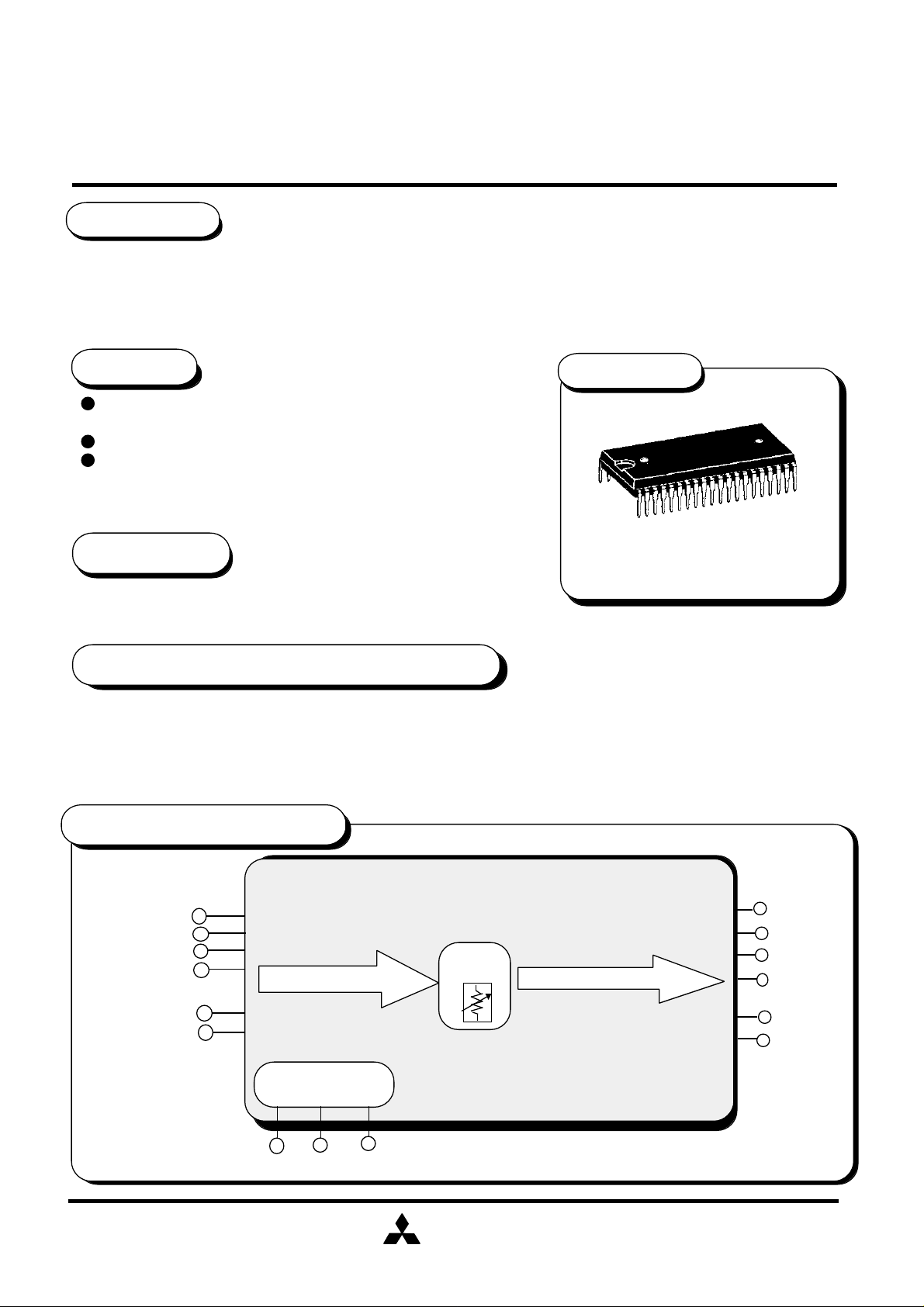
The M62447SP is 6 channels electric volume controlled 3-wire serial data.
The IC is suitable for use in home-use audio systems and TV sets.
FEATURES
Electric volume
•Volume level•••••••• 0dB ~ -79dB,- ∞ dB (1dB / step)
4 Output ports
Built-in microcomputer interface circuit controlled by 16-bit serial
data.
APPLICATION
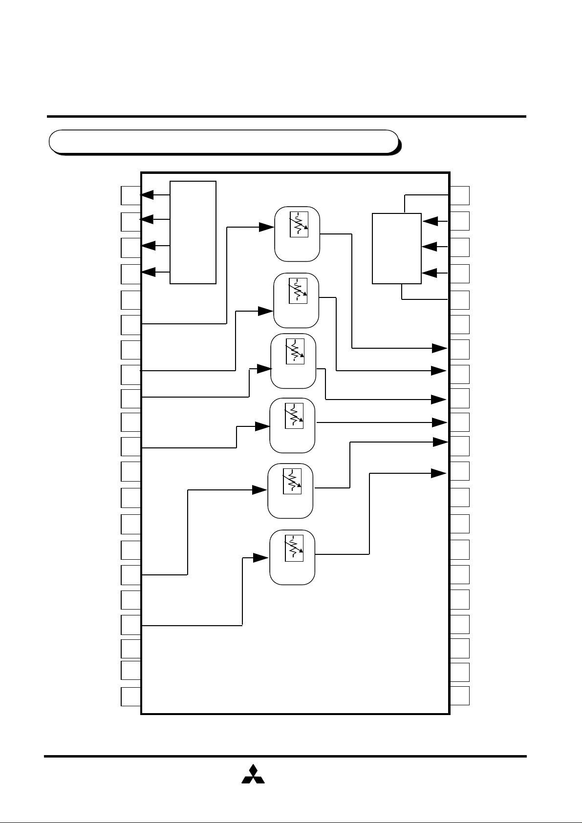
PACKAGE
Outline
42P4B
DVD,Home Audio equipment,TV
RECOMMENDED OPERATING CONDITIONS
Supply voltage range•••• ±4.5 ~ ±7.3V (analog)
4.5 ~ 5.5V (digital)
Rated supply voltage •••• ±7.0V (analog)
5.0V (digital)
SYSTEM BLOCK DIAGRAM
C in
SW in
SL in
SR in
L in
R in
volume
Cout
SWout
SLout
SRout
Lout
Rout
LATCH
µ -com
interface
DATA
CLK
MITSUBISHI
ELECTRIC
( / 12 )
1
Page 2
MITSUBISHI SOUND PROCESSORS
PRELIMINARY
Notice ; This is not a final specification.
some parametric limits are subject to change.
PIN CONFIGURATION AND IC INTERNAL BLOCK DIAGRAM
1
OUT3
OUT2
OUT1
AVDD
SWin
GNDS
2
3
4
5
6
7
OUTPUT
PORT
volume
volume
M62447SP
6CH ELECTRIC VOLUME
DVDDOUT4
42
CLK
MCU
I/F
41
40
39
38
37
36
DATA
LATCH
DGND
AGND
SW out
SRin
SLin
GNDC
Cin
GNDR1
GNDR2
GNDL1
GNDL2
Rin
GNDLR
Lin
NC
8
9
10
11
12
13
14
15
16
17
18
19
volume
volume
volume
volume
35
34
33
32
31
30
29
28
27
26
25
24
SRout
SLout
Cout
Rout
Lout
AVSS1
AVSS2
NC
NC
NC
NC
NC
NC
NC
20
21
MITSUBISHI
ELECTRIC
NC
23
22
NC
( / 12 )
2
Page 3
MITSUBISHI SOUND PROCESSORS
PRELIMINARY
Notice ; This is not a final specification.
some parametric limits are subject to change.
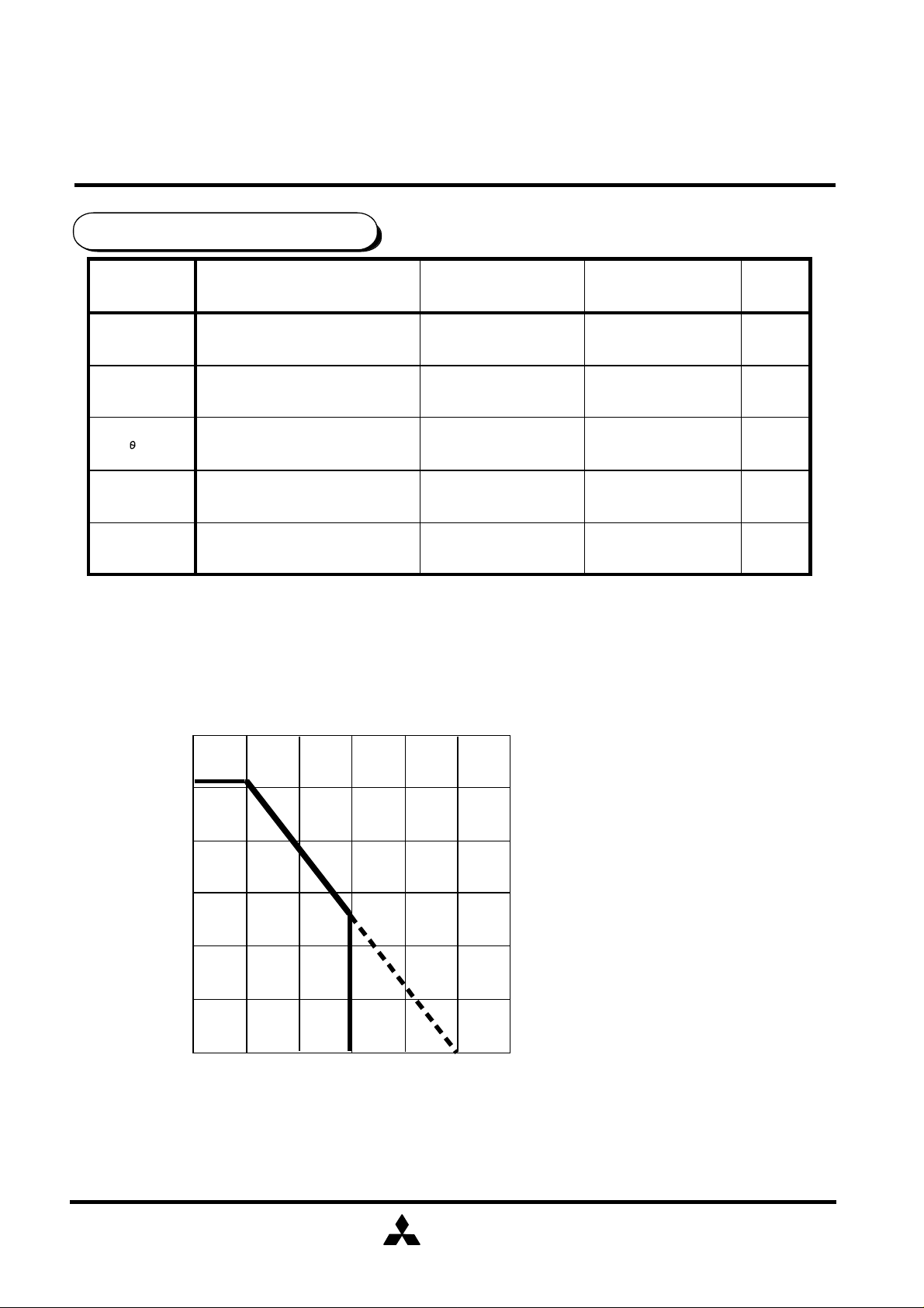
ABSOLUTE MAXIMUM RATINGS
Symbol
Vsupply
Pd
K
Topr
Tstg
Operating temperature
Parameter Conditions Ratings Unit
Supply Voltage
Power dissipation
Thermal derating
Storage temperature
AVDD-AVSS
Ta≤25°C
Ta>25°C,
*standard board
M62447SP
6CH ELECTRIC VOLUME
15.0
1260
12.6
-20 ~ +75
-40 ~ +125
V
mW
mW/°C
°C
°C
THERMAL DERATING
(MAXIMUM RATING)
1.5
1260
1.0
0.5
POWER DISSIPATION pd [W]
0
0
25 50 75 100
AMBIENT TEMPERATURE Ta [°C]
125
*Standard board
150
MITSUBISHI
ELECTRIC
( / 12 )
3
Page 4
MITSUBISHI SOUND PROCESSORS
PRELIMINARY
Notice ; This is not a final specification.
some parametric limits are subject to change.
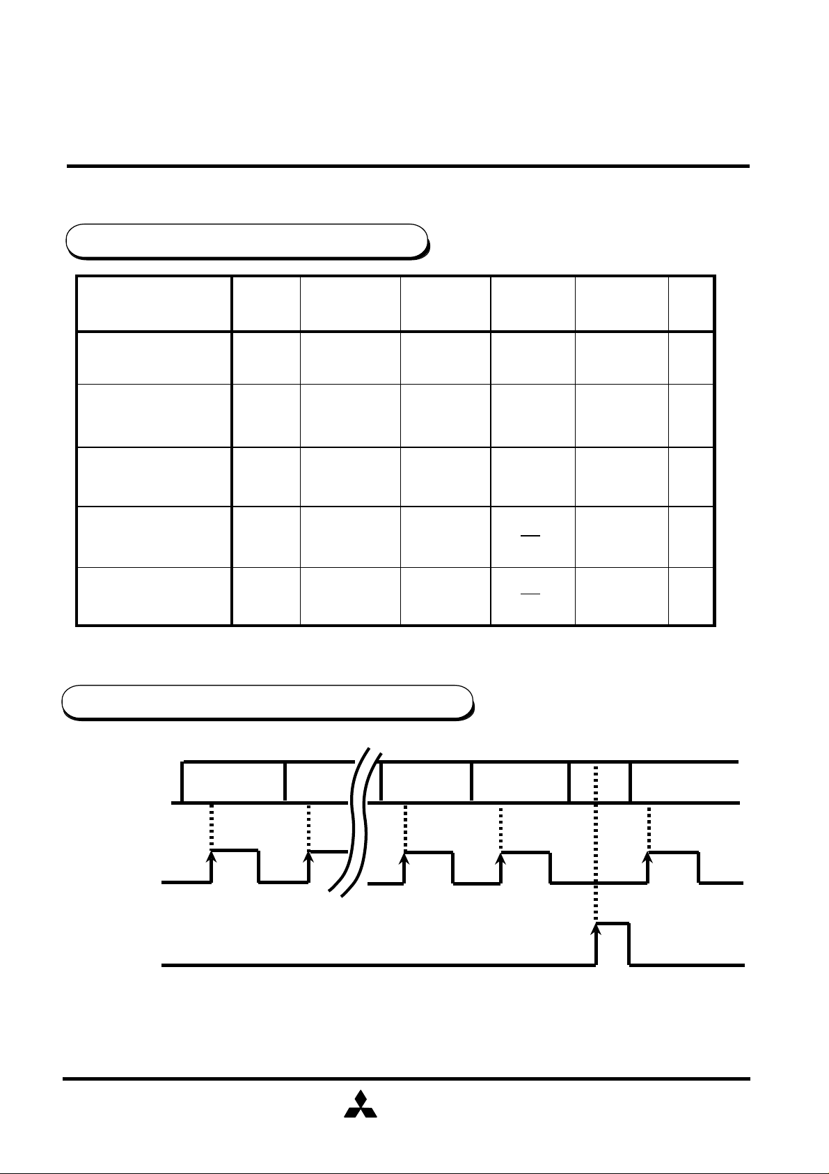
RECOMMENDED OPERATING CONDITION
Parameter Symbol Condition
Analog positive
Supply Voltage
Analog negative
Supply Voltage
Digital
Supply Voltage
AVDD
AVSS
DVDD
MIN TYP
4.5
-7.3
4.5
7.0
-7.0
5.0
M62447SP
6CH ELECTRIC VOLUME
MAX
7.3
-4.5
5.5
Unit
V
V
V
High-level Input
VIH
DVDD/2+1
Voltage
Low-level Input
Voltage
VIL
DGND
(note)AVSS≤DGND<DVDD≤AVDD
DATA TIMING (Recommended conditions)
H
DATA
CLOCK
LATCH
D0
L
H
L
H
D1
DVDD
DVDD/2-1
DFDE
V
V
D0
L
note : CLOCK and LATCH function at raising edges of pulse .
MITSUBISHI
ELECTRIC
( / 12 )
4
Page 5

MITSUBISHI SOUND PROCESSORS
PRELIMINARY
Notice ; This is not a final specification.
some parametric limits are subject to change.
CLOCK, DATA,LATCH TIMING
CLOCK
DATA
75%
25%
tr tf
tWHC
25%
75%
M62447SP
6CH ELECTRIC VOLUME
cr
t
WLC
t
tr
LATCH
DIGITAL BLOCK TIMING REGULATION
Symbol
t cr
t WHC
t WLC
r
t
t f
t SD
t
HD
tSL
tWHL
CLOCK cycle time
CLOCK pulse width ("H"level)
CLOCK pulse width ("L"level)
CLOCK,DATA,LATCH rise time
CLOCK,DATA,LATCH fall time
DATA setup time
DATA hold time
LATCH setup time
LATCH pulse width
Parameter
tSL
tf
tWHC
tr
tf
75%
25%
SD
t
HD
t
Limits
0.8
0.8
Unit
µsec
Min
8
3.2
3.2
1.6
1.6
2
3.2
typ
Max
MITSUBISHI
ELECTRIC
( / 12 )
5
Page 6

MITSUBISHI SOUND PROCESSORS
PRELIMINARY
Notice ; This is not a final specification.
some parametric limits are subject to change.
M62447SP
6CH ELECTRIC VOLUME
DIGITAL CONTROL SPECIFICATION
Fore kinds of input format options are available by changing slot settings of DE and DF.
(When the IC is powered up , the internal settings are not fixed.)
( 1 )
( 2 )
DO1 D11 D21 D31 D41 D51 D61 D71
1 2 3 4
0 0
DO2 D12 D22 D32 D42 D52 D62 D72
0
OUTPUT PORT n
0
1: High
0: Low
0
VOLUME Rch
DFDED81 D91 DA1 DB1 DC1 DD1
0 0
1
0 0
0
0
DFDED82 D92 DA2 DB2 DC2 DD2
0 1VOLUME Lch
( 3 )
( 4 )
DO3 D13 D23 D33 D43 D53 D63 D73
VOLUME Cch VOLUME SWch
DO4 D14 D24 D34 D44 D54 D64 D74
VOLUME SLch VOLUME SRch
DFDED83 D93 DA3 DB3 DC3 DD3
01
DFDED84 D94 DA4 DB4 DC4 DD4
11
MITSUBISHI
ELECTRIC
( / 12 )
6
Page 7

MITSUBISHI SOUND PROCESSORS
PRELIMINARY
Notice ; This is not a final specification.
some parametric limits are subject to change.
SETTING CODE
(1) Port output
D41 D51 D61 D71
L
PORT1
PORT2
PORT3
PORT4
0
1
0
1
0
1
0
1
- - -
H
-
-
-
L
H
-
- -
-
L
H
M62447SP
6CH ELECTRIC VOLUME
Note : Do not input other data than the above.
-
-
L
H
MITSUBISHI
ELECTRIC
( / 12 )
7
Page 8

MITSUBISHI SOUND PROCESSORS
PRELIMINARY
Notice ; This is not a final specification.
some parametric limits are subject to change.
(2) VOLUME ( 0 ~ -39dB)
A
T
VOLUME
T
- 0 dB
- 1 dB
- 2 dB
- 3 dB
- 4 dB
- 5 dB
- 6 dB
- 7 dB
- 8 dB
- 9 dB
- 10 dB
- 11 dB
- 12 dB
- 13 dB
- 14 dB
- 15 dB
- 16 dB
- 17 dB
- 18 dB
- 19 dB
- 20 dB
- 21 dB
- 22 dB
- 23 dB
- 24 dB
- 25 dB
- 26 dB
- 27 dB
- 28 dB
- 29 dB
- 30 dB
- 31 dB
- 32 dB
- 33 dB
- 34 dB
- 35 dB
- 36 dB
- 37 dB
- 38 dB
- 39 dB
D0X D1X
D7X D8X
0 0
0 0
0
0
0
0
0 0
0 0
0 0
0 0
0
0
0
0
0 0
0 0
0 0
0 0
0
0
0
0
0 0
0 0
0 0
0 0
0
0
0
0
0 0
0 0
0 1
0 1
0
0
0
0
0 1
0 1
M62447SP
6CH ELECTRIC VOLUME
Note : Do not input other data than the above.
D2X
D9X
D3X
DAX
0
0
0
0
0
0
0
0
0
0
0
0
0
0
0
0
0
0
0
0
0
0
0
0
1
1
0
0
0
0
1
1
1
1
1
1
1
1
0
0
0
0
1
1
1
1
1
1
0
0
1
1
1
1
0
0
0
0
0
0
D4X
DBX
0
0
0
0
0
0
0
0
1
1
1
1
1
1
1
1
0
0
0
0
0
0
0
0
1
1
1
1
1
1
1
1
0
0
0
0
0
0
0
0
D5X
DCX
0
0
0
0
1
1
1
1
0
0
0
0
1
1
1
1
0
0
0
0
1
1
1
1
0
0
0
0
1
1
1
1
0
0
0
0
1
1
1
1
D6X
DDX
0
0
1
1
0
0
1
1
0
0
1
1
0
0
1
1
0
0
1
1
0
0
1
1
0
0
1
1
0
0
1
1
0
0
1
1
0
0
1
1
0
1
0
1
0
1
0
1
0
1
0
1
0
1
0
1
0
1
0
1
0
1
0
1
0
1
0
1
0
1
0
1
0
1
0
1
0
1
0
1
MITSUBISHI
ELECTRIC
( / 12 )
8
Page 9

MITSUBISHI SOUND PROCESSORS
PRELIMINARY
Notice ; This is not a final specification.
some parametric limits are subject to change.
VOLUME ( -40 ~ - ∞dB)
A
T
VOLUME
T
- 40 dB
- 41 dB
- 42 dB
- 43 dB
- 44 dB
- 45 dB
- 46 dB
- 47 dB
- 48 dB
- 49 dB
- 50 dB
- 51 dB
- 52 dB
- 53 dB
- 54 dB
- 55 dB
- 56 dB
- 57 dB
- 58 dB
- 59 dB
- 60 dB
- 61 dB
- 62 dB
- 63 dB
- 64 dB
- 65 dB
- 66 dB
- 67 dB
- 68 dB
- 69 dB
- 70 dB
- 71 dB
- 72 dB
- 73 dB
- 74 dB
- 75 dB
- 76 dB
- 77 dB
- 78 dB
- 79 dB
- ∞ dB
D0X D1X
D7X D8X
0 1
0 1
0
0
0
0
0 1
0 1
0 1
0 1
0
0
0
0
0 1
0 1
0 1
0 1
0
0
0
0
0 1
0 1
1 0
1 0
1
1
1
1
1 0
1 0
1 0
1 0
1
1
1
1
1 0
1 0
1
M62447SP
6CH ELECTRIC VOLUME
Note : Do not input other data than the above.
D2X
D9X
D3X
DAX
0
0
1
1
1
1
0
0
0
0
0
0
1
1
1
1
1
1
1
1
1
1
1
1
1
1
1
1
1
1
1
1
1
1
1
1
0
0
0
0
0
0
0
0
0
0
0
0
0
0
0
0
0
0
0
0
0
0
0
0
1 0 0 0 00
D4X
DBX
1
1
1
1
1
1
1
1
0
0
0
0
0
0
0
0
1
1
1
1
1
1
1
1
0
0
0
0
0
0
0
0
1
1
1
1
1
1
1
1
D5X
DCX
0
0
0
0
1
1
1
1
0
0
0
0
1
1
1
1
0
0
0
0
1
1
1
1
0
0
0
0
1
1
1
1
0
0
0
0
1
1
1
1
D6X
DDX
0
0
1
1
0
0
1
1
0
0
1
1
0
0
1
1
0
0
1
1
0
0
1
1
0
0
1
1
0
0
1
1
0
0
1
1
0
0
1
1
0
1
0
1
0
1
0
1
0
1
0
1
0
1
0
1
0
1
0
1
0
1
0
1
0
1
0
1
0
1
0
1
0
1
0
1
0
1
0
1
MITSUBISHI
ELECTRIC
( / 12 )
9
Page 10

MITSUBISHI SOUND PROCESSORS
PRELIMINARY
Notice ; This is not a final specification.
some parametric limits are subject to change.
ELECTRICAL CHARACTERISTICS
(Ta=25°C, AVDD=7.0V , AVSS=-7.0V , DVDD=5.0V , f=1kHz, unless otherwise noted.
TONE CONTROL , VOLUME are set to 0dB )
(1) Power supply characteristics
SymbolParameter Test condition
Analog positive circuit current
Analog negaitive circuit current
Digital circuit current
(2) Input / Output characteristics
AIdd
AIss
DIdd
Current at pin 5
No signal
Current at pin 29 ~ 30
No signal
Current at pin 42
No signal
M62447SP
6CH ELECTRIC VOLUME
Min
Limits
typ
25 mA35
25 35
0.5
Max
2.0
Unit
mA
mA
Maximum output voltage
Pass gain
Distortion
Output noise voltage
Maximum attenuation
Volume gain
between channels
SymbolParameter Test condition
Min
6,8,9,11,16,18pin INPUT
31 ~ 36pin OUTPUT
VOM RL =10KΩ,THD=1%
Vi=0.2Vrms,FLAT
Gv
THD
Vn(VOL)
ATTmax -86
Dvol
6,8,9,11,16,18pin INPUT
31 ~ 36pin OUTPUT
BW=400 ~ 30kHz
Vi=0.2Vrms , RL=10KΩ
31 ~ 36pin,Rg=0KΩ,
JIS-A,VOL=0dB
31 ~ 36pin,Rg=1KΩ,
JIS-A,VOL=-∞dB
-1.5 1.5
Limits
typ
4.0 Vrms3.0
0
2 µVrms6
0
Max
2.0-2.0
Unit
dB
%0.090.02
dB
dB
Crosstalk between channels
Port output current
CT
IL mA
Vo=0.5Vrms , RL=10KΩ,JIS-A
Rg=1KΩ
MITSUBISHI
ELECTRIC
-65
-80
0.2
( / 12 )
10
dB
Page 11

MITSUBISHI SOUND PROCESSORS
PRELIMINARY
Notice ; This is not a final specification.
some parametric limits are subject to change.
+
3.3µF
M62447SP
6CH ELECTRIC VOLUME
3.3µF
+
VOLUME Lch,Rch (0dB~-∞)
SYSTEM DIAGRAM
VOLUME in
70kΩ
3.3µF
VOLUME Cch,SWch,SLch,SRch (0dB~-∞)
VOLUME in
3.3µF
by attenuated condition.
The resistance value of VOLUME change about 17~24KΩ
OUTPUT PORT
DVDD(=5V)
MITSUBISHI
ELECTRIC
( / 12 )
11
Page 12

MITSUBISHI SOUND PROCESSORS
PRELIMINARY
Notice ; This is not a final specification.
some parametric limits are subject to change.
APPLICATION EXAMPLE
22KΩ
OUT4
OUT3
OUT2
OUT1
AVDD=7V
1KΩ
SWin
1KΩ
SRin
1KΩ
SLin
1KΩ
Cin
22KΩ
22KΩ
22KΩ
3.3µF
3.3µF
3.3µF
3.3µF
1
2
3
4
5
6
7
8
9
10
11
12
OUTPUT
PORT
volume
volume
volume
volume
MCU
I/F
M62447SP
6CH ELECTRIC VOLUME
42
41
40
39
38
37
3.3µF
36
3.3µF
35
3.3µF
34
3.3µF
33
3.3µF
32
3.3µF
31
DVDD=5V
MCU
DGND
AGND
10KΩ
SWout
10KΩ
SRout
10KΩ
SLout
10KΩ
Cout
10KΩ
Rout
10KΩ
Lout
Rin
Lin
1KΩ
1KΩ
3.3µF
3.3µF
13
14
15
16
17
18
19
20
21
volume
volume
MITSUBISHI
ELECTRIC
30
AVSS=-7V
29
28
27
26
25
24
23
22
Units Resistance : Ω
Capacitance : F
( / 12 )
12
 Loading...