

Page 1

MITSUBISHI ELECTRIC
PRELIMINARY
Notice ; This is not a final specification.
some parametric limits are subject to change.
SRS F
SRS F
DESCRIPTION
This is an IC for car audio.
F( )cus system can realize more optimal speaker position.
FEATURE
Built-in F( )cus (Woofer position can be changed
by the outside resisters.)
Built-in SRS
SRS ON/OFF mode and FOCUS ON/OFF mode
can be controlled by the DC voltage.
( ))
cus, SRS 3D Stereo Sound Controller
(
cus, SRS 3D Stereo Sound Controller
M62436FP
SOUND CONTROLLER WITH
SRS FOCUS & SRS SURROUND
36P2R
RECOMMENDED OPERATING CONDITION
Supply voltage range••••••••••Vcc=7 ~ 9V
Rated supply voltage•••••••••••Vcc=8V
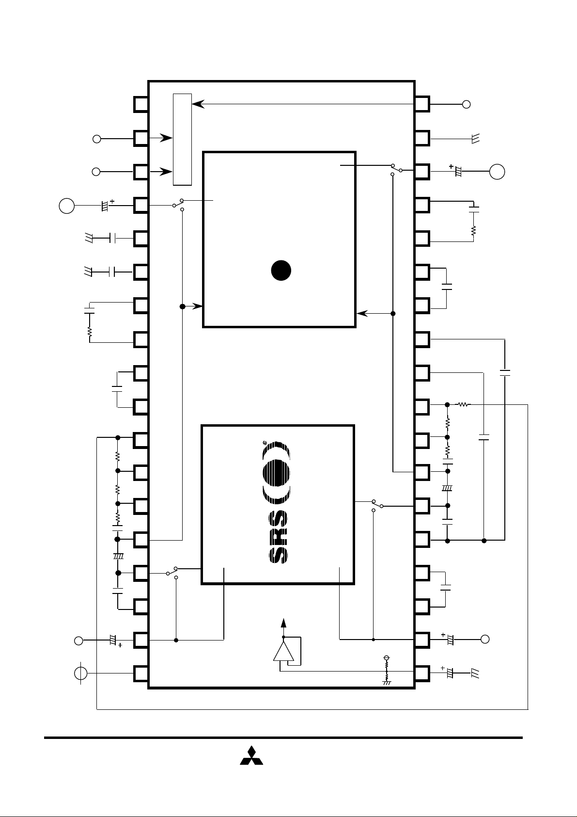
SYSTEM BLOCK DIAGRAM
Tone
Tone
M62419FP
Lin
Rin
Rear L
Rear R
Front L
F( )CUS
Front R
M62436FP
SRS
ON/OFF
MITSUBISHI
ELECTRIC
Interface
FOCUS
ON/OFF
FOCUS Position
H/L
(1/10)
Page 2
N.C.
FOCUS
Position H/L
20 19
21
0.01µ
0.1µ
25 24 23
27 26 22
C13
29 28
R15
30
R14
3136
R13
C9
32
NP
3334
C6
OUT
FOCUS
ON/OFF
SRS
ON/OFF
2.2µ
390p
C17
R39
2.4K
C9
C6
0.0039µ
390
390 200
0.22µ
2.2µ
470p
Block Diagram & Application Example
IN
35
2.2µ
I/F
FOCUS IN
SRS OUT
F( )CUS
REF
+
-
17 18
16
15
12 13 1410
11
8 9
FOCUS IN
7
SRS OUT
61
5
43
2
NP
C1
C12
R17
R16
C10
C7
0.0039µ
200
390
0.22µ
2.2µ
470p
0.018µ
2.2µ
10µ
2.2µ
C16
R41
390
R18
2.4K
C2
390p
C3
0.01µ
OUT
0.82µ
IN
VCC
MITSUBISHI
ELECTRIC
Cref
(2/10)
Page 3
ABSOLUTE MAXIMUM RATINGS
Symbol Parameter Conditions Ratings Unit
Vcc,Vdd V
Pd
K mW/°CTa>25
Topr
Tstg
Supply Voltage
Power Dissipation
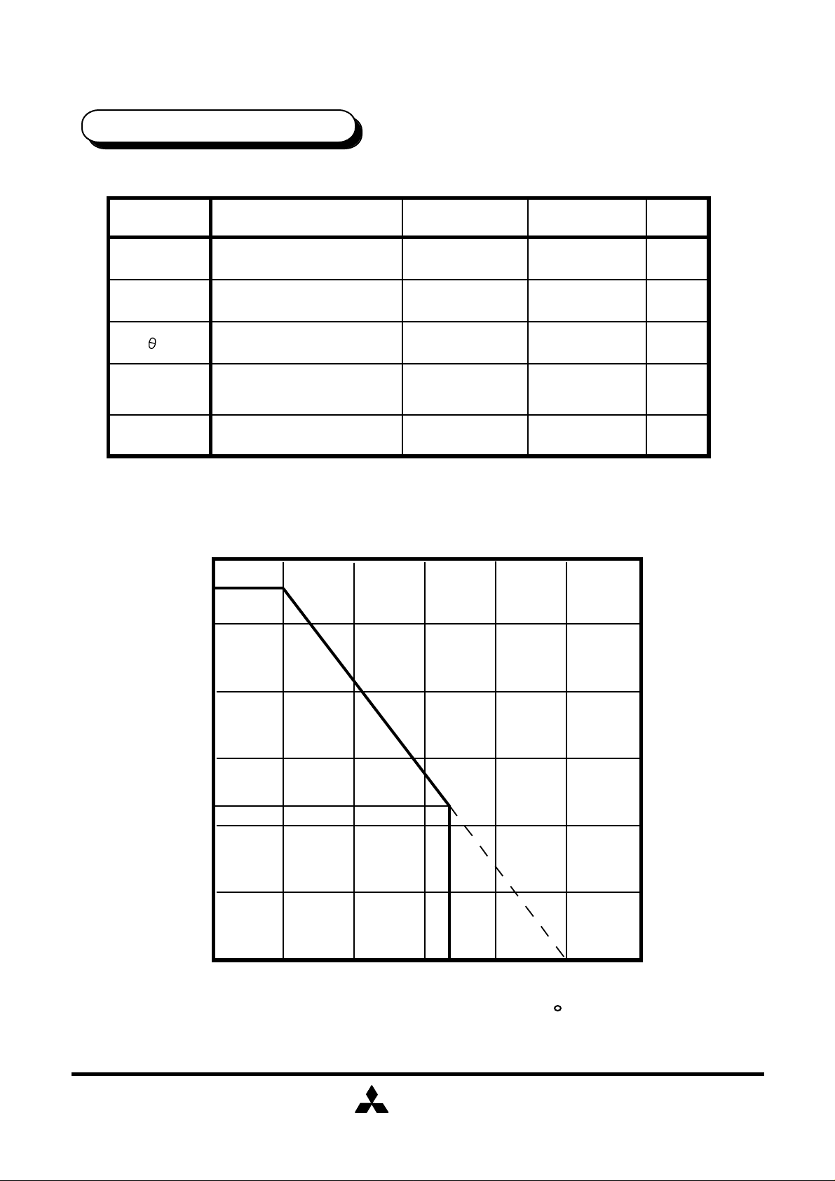
Thermal Derating
Operating Temperature
Storage Temperature
Ta≤25
12
1120
1.12
-20 ~ +75
-55 ~+ 125
mW
°C
°C
Thermal Derating
1200
1120
1000
800
600
450
400
Power Dissipation Pd [ mW ]
200
25 50 75 100
AMBIENT TEMPERATURE Ta [ C ]
85
MITSUBISHI
ELECTRIC
125 150
(3/10)
Page 4

ÉAÉiÉçÉOâÒòHìdó¨
ELECTRICAL CHARACTERISTICS
AIdd
(1) Power Supply Characteristics
Parameter Conditions Unit
Symbol
Icc
(2) Input / Output Characteristics
Parameter Conditions
Maximum
Output Voltage
Maximum
Input Voltage
Symbol
VIM1
VIM2
VIM3
Input; pin2,35
Output; pin16, 22
RL=10KΩ,THD=1%
Input; pin2,35 /Output; pin16, 22
SRS ON,FOCUS OFF
THD=1%
Input; pin2,35 /Output; pin16, 22
SRS ON
FOCUS Position"H" ON
THD=1%
(Ta=25°C,Vcc=8.0V, f=1kHz)
Limit
Min
36pin Icc
No Signal
Ta=25°C,Vcc=8.0V, f=1kHz
R13=R16=390,R14=R17=200
R15=R18=390
f=150Hz
f=1KHz
f=20KHz
typ
22
Min
1.6VOMt
0.32
0.25
0.2
Max
45
Limit
typ
1.9
0.65
0.5
0.4
mACircuit Current
Unit
Max
Vrms
Vrms
Pass Gain
Output Noise
Voltage
Channel
Separation
Gvt
Gv1
Gv2
Gv3
Vno1
Vno2
Vno3
CT
Vi=100mVrms
SRS, Focus OFF
Input; pin2,35 /Output; pin16, 22
Vi=100mVrms
Input; pin2,35 /Output; pin16, 22
SRS ON,FOCUS OFF
Vi=100mVrms
SRS ON
FOCUS Position"H" ON
(2pin,35pin)-(16, 22Pin)
Rg=0(2,35pin)
SRS OFF ,FOCUS OFF
DIN-AUDIO filter
Rg=0(2,35pin)
SRS ON ,FOCUS OFF
DIN-AUDIO filter
Rg=0(2,35pin),
SRS ON, FOCUS Position"H" ON
DIN-AUDIO filter
Input Side:f=1KHz,Vi=0.5Vrms
Monitor Side:Rg=0, IHF-A filter
Focus:OFF, SRS:OFF
RL=10KΩ
f=150Hz
f=1KHz
f=20KHz
0
2.0-2.0
10
7
10
12 18
13
15
5.0
18
50
13
16
15
40
90
dB
µVrms
dB-90 -75
MITSUBISHI
ELECTRIC
(4/10)
Page 5

(3) DC Control Characteristic of the Switch Block
VIH "H" Level Input Voltage Pin 18,20,21
V
IL
"L" Level Input Voltage Pin 18,20,21
Limit
Min
typ
Max
2.1 Vcc
~
0 0.8
~
UnitSymbol Parameter Condition
V
V
MITSUBISHI
ELECTRIC
(5/10)
Page 6

Switch Condition and the Mode
SRS 3D Stereo
21
SRS ON
SRS OFF
FOCUS Position
18
FOCUS position "H"
FOCUS position "L"
SRS ON/OFF
Switch
H
L
FOCUS H/L
Switch
H
L
20 FOCUS
FOCUS ON
FOCUS OFF
FOCUS ON/OFF
Switch
H
L
*Bypass mode can be set by both SRS ON/OFF switch and FOCUS
ON/OFF switch are set to "L".
MITSUBISHI
ELECTRIC
(6/10)
Page 7

Regarding to the outside registers
R16(R13),R17(R14),R18(R15)
The resisters of R16(R13),R17(R14),R18(R15) can be set the
FOCUS position.
C10
7
0.22µ
R16
*This figure shows only the side channel.
8
R17
9
R18
29
1. The setting of the FOCUS position "H"
R17 + R18
R16 +R17 + R18
2. The setting of the FOCUS position "L"
R18
R16 +R17 + R18
FOCUS position "H"
FOCUS position "L"
*please keep the following formula.
R16+R17+R18 = 1KΩ
.
.
(Example)
In the case of R16 = 390Ω,R17 = 200Ω,R18 = 390Ω
.
FOCUS position "H" = 60%
FOCUS position "L" = 40%
.
.
.
MITSUBISHI
ELECTRIC
(7/10)
Page 8

Between Pin14(26) and Pin15(25)
Add 10K of resistors between Pin14(26) and Pin15(25), can adjust the
difference between the sound level of Focus ON and the sound level of
Focus OFF.
Also add 10K of resistors between Pin14(26) and Pin15(25),can decrease
the Focus gain.
Then the maximum input voltage and the output noise voltage can be
improved.
(Reference)
In the case of
R13=R16=390,R14=R17=200,R15=R18=390
Add 10Kof resistors between Pin14(26) and Pin15(25)
Parameter Conditions
Maximum
Output Voltage
Maximum
Input Voltage
Pass Gain
Symbol
VOMt
VIM1
VIM2
VIM3
Gvt
Gv1
Gv2
Gv3
Input; pin2,35
Output; pin16, 22
RL =10KΩ,THD=1%
Input; pin2,35 /Output; pin16, 22
SRS ON,FOCUS OFF
THD=1%
Input; pin2,35 /Output; pin16, 22
SRS ON
FOCUS Position"H" ON
THD=1%
Vi=100mVrms
SRS, Focus OFF
Input; pin2,35 /Output; pin16, 22
Vi=100mVrms
Input; pin2,35 /Output; pin16, 22
SRS ON,FOCUS OFF
Vi=100mVrms
SRS ON
FOCUS Position"H" ON
(2pin,35pin)-(16, 22Pin)
f=150Hz
f=1KHz
f=20KHz
f=150Hz
f=1KHz
f=20KHz
1.9
0.65
0.85
0.67
0
10
7
9
UnitTyp.
Vrms
Vrms
dB
Output Noise
Voltage
Channel
Separation
Vno1
Vno2
Vno3
CT
Rg=0(2,35pin)
SRS OFF ,FOCUS OFF
DIN-AUDIO filter
Rg=0(2,35pin)
SRS ON ,FOCUS OFF
DIN-AUDIO filter
Rg=0(2,35pin),
SRS ON, FOCUS Position"H" ON
DIN-AUDIO filter
Input Side:f=1KHz,Vi=0.5Vrms
Monitor Side:Rg=0, IHF-A filter
Focus:OFF, SRS:OFF
RL=10KΩ
MITSUBISHI
ELECTRIC
5.0
18
30
-90
µVrms
dB
(8/10)
Page 9

System Circuit Example
(The following figures show only the side channel.)
1. In the case of SRS 3D stereo is effective for the front speakers.
M62419FP/M62440FP
Front Fader
M62436FP
TONE SRS FOCUS
Master
Volume
Rear Fader
Rear
2. In the case of SRS 3D stereo is effective for the front and rear speakers.
(FOCUS is effective for the front speakers.)
M62436FP
Front
M62419FP/M62440FP
TONE
Master
Volume
SRS
Front Fader
Rear Fader
MITSUBISHI
ELECTRIC
FOCUS
Front
Rear
(9/10)
Page 10

NOTE
Each switches (SRS ON/OFF, FOCUS ON/OFF and FOCUS
Position H/L Switches) does not have the countermeasure
for click noise, so that we recommend outside mute circuit.
SRS,the SRS logo,Sound Retrieval System and "everything else
is only stereo" are registered trademarks of SRS Labs, Inc.
This device available only to licensees of SRS Lab,Inc.
Licensing and application information may be obtained from
SRS Lab, Inc.
Mitsubishi Electric Corporation assumes no responsibility for any
damage,or infringement of any third-party's rights, originating in
the use of any product data, diagrams, charts or circuit application
examples contained in these materials.
MITSUBISHI
ELECTRIC
(10/10)
 Loading...