

Page 1
PRELIMINARY
PRELIMINARY
Notice ; This is not a final specification.
some parametric limits are subject to change.
MITSUBISHI SOUND PROCESSOR
M62434FP
SOUND CONTROLLER FOR TV
Tone, Volume and SRS by I C Bus System
2
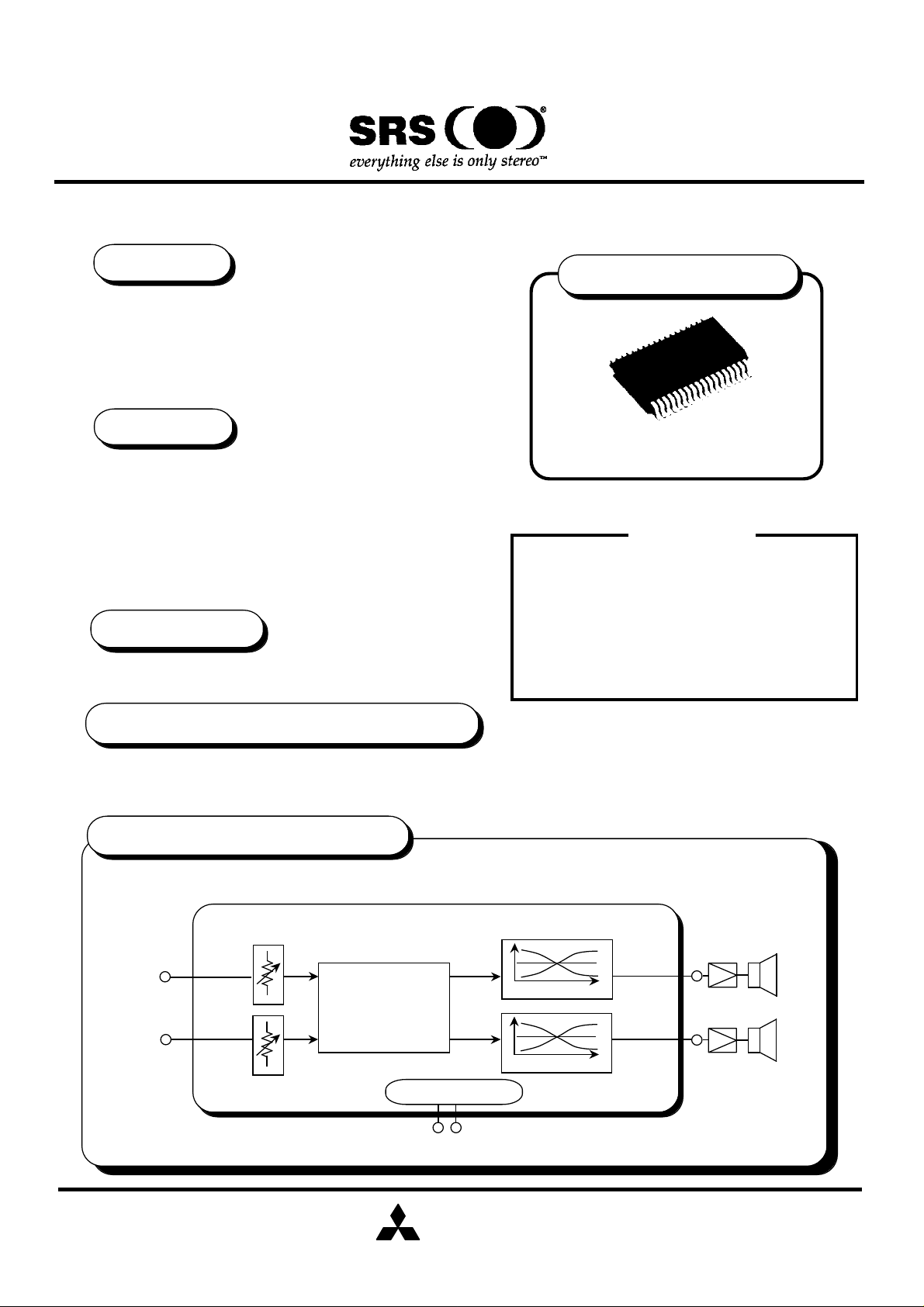
OUTLINE
M62434FP has tone, volume and SRS 3D
stereo controlled by I C bus.
This IC broad applications because of low
noise and distortion.
2
FEATURE
•TONE(Bass/Treble) control, 1dB step
volume, and 3dB/step SRS "Space" and "Center"
controls.
•Controlled by serial data in accordance
with the I C bus format .
2
APPLICATION
• TV , Mini-Stereo , etc
SRS,the SRS logo,Sound Retrieval System and
"everything else is only stereo" are registered trademarks
of SRS Labs, Inc.
This device available only to licensees of SRS
Lab,Inc. Licensing and application information
may be obtained from SRS Lab, Inc.
Mitsubishi Electric Corporation assumes no responsibility
for any damage,or infringement of any third-party's rights,
originating in the use of any product data, diagrams, charts
or circuit application examples contained in these
materials.
PACKAGE OUTLINE
24Pin SOP
Note !!
RECOMMENDED OPERATING CONDITION
•Supply voltage range 8.5~9.5V (analog)
•Rated supply voltage 9V (analog)
SYSTEM BLOCK DIAGRAM
Volume
SRS3D Stereo
&
Pseudo Stereo
2
I C BUS Interface
SCL SDA
Tone Control
Bass
Bass Treble
Treble
1
D-62434-74F
MITSUBISHI
ELECTRIC
( / )
13
1
Page 2

MITSUBISHI SOUND PROCESSOR
PRELIMINARY
Notice ; This is not a final specification.
some parametric limits are subject to change.
BLOCK DIAGRAM
GND
SCL
SDA
1317
14
15
I2C BUS
INTERFACE
6.5K
M62434FP
SOUND CONTROLLER FOR TV
6.5K
OUT R
11 12
TRE R
BASS 2R
Vdd
OUT L
TRE L
BASS 2L
BASS 1L
SRSIN L
VOLOUT L
VOLIN L
REF IN
16
18
19
20
21
22
2324
6.5K
6.5K
SRS 3D
IN L
Stereo &
Psuedo
Stereo
IN R
9
BASS 1R
8
REF OUT
7 10
PSEUDO
6
FILTER
5
DIFF
43
SRSIN R
VOLOUT R
VOLIN R
1 2
Vcc
D-62434-74F
MITSUBISHI
ELECTRIC
( / )
13
2
Page 3
MITSUBISHI SOUND PROCESSOR
PRELIMINARY
Notice ; This is not a final specification.
some parametric limits are subject to change.
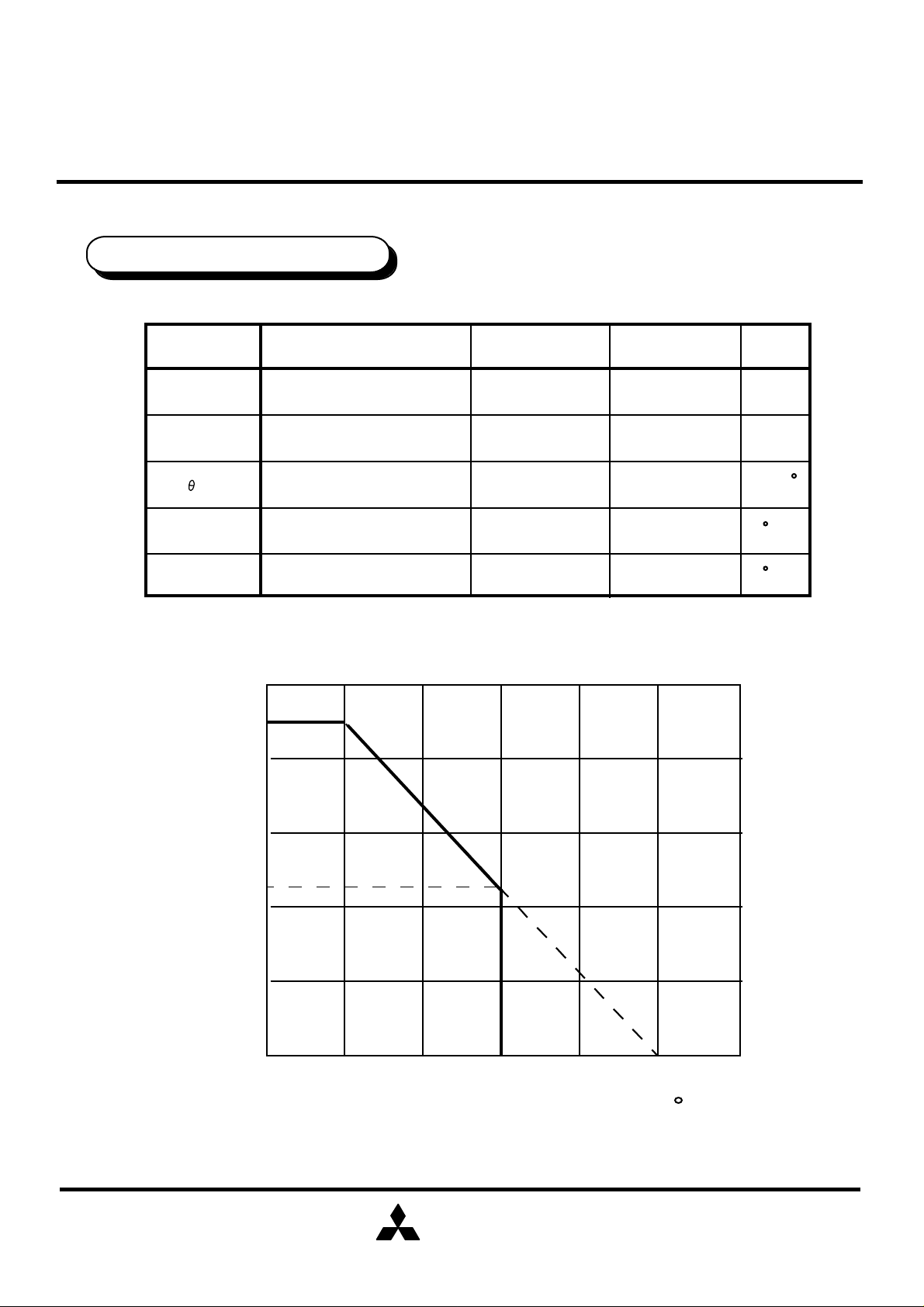
ABSOLUTE MAXIMUM RATINGS
Symbol Parameter Conditions Ratings Unit
Vcc Supply Voltage 10.0 V
Pd Power Dissipation 900
K Thermal Derating 9
Topr Operating Temperature
Storage Temperature -55 ~ 125Tstg
Ta>25°C
M62434FP
SOUND CONTROLLER FOR TV
mWTa<25°C
mW/ C
-20 ~ 75
C
C
Thermal Derating
1000
900
800
600
450
400
200
Power Dissipation Pd [ mW ]
25 50 75 100
AMBIENT TEMPERATURE Ta [ C ]
125 150
D-62434-74F
MITSUBISHI
ELECTRIC
( / )
13
3
Page 4
MITSUBISHI SOUND PROCESSOR
PRELIMINARY
Notice ; This is not a final specification.
some parametric limits are subject to change.
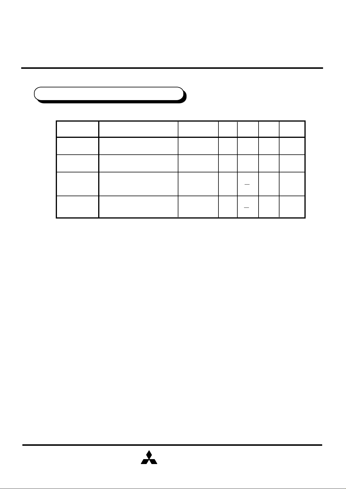
RECOMMENDED OPERATING CONDITION
Symbol Parameter Conditions Unit
AVDD Analog Supply Voltage V
DVDD Digital Supply Voltage
VIH
VIL
High Level
Input Voltage
Low Level
Input Voltage
M62434FP
SOUND CONTROLLER FOR TV
Min.
8.5
4.5
0.7
DVDD
0
Typ. Max.
9.0 9.5
5.0 5.5
VDD
0.3
DVDD
V
V
V
D-62434-74F
MITSUBISHI
ELECTRIC
( / )
13
4
Page 5

MITSUBISHI SOUND PROCESSOR
PRELIMINARY
Notice ; This is not a final specification.
some parametric limits are subject to change.
ELECTRICAL CHARACTERISTICS
(Ta=25°C, Vcc=9V, Tone Control;Flat , Bass Boost;0dB, ATT=0dB)
(1) Power Suppy Characteristics
Symbol Parameter Conditions Unit
Icc Circuit Current mA
(2) -1 Input / Output Characteristics
Symbol
VIM1
VIM2
VOM
THD
Parameter
Maximum
Input Voltage1
Maximum
Input Voltage2
Maximum
Output Voltage
Total
Harmonic
Distortion
Vi=0dBm
Conditions
Input Output
pin 2,23
f=1kHz
pin 2,23
f=100Hz
pin 2,23
f=1kHz
pin 2,23
f=1kHz
pin 12,17
THD=1%
IHF-A filter
pin 12,17
THD=1%
DIN-A filter
pin 12,17
THD=1%
IHF-A filter
RL=10KΩ
pin 12,17
DIN-A filter
RL=10KΩ
ATT
(dB)
-6
0
0
0
Min.
SRS TONE
ByPass
Center
0dB
Space
0dB
ByPass
ByPass
M62434FP
SOUND CONTROLLER FOR TV
Typ. Max.
30 45
Flat
Bass
12dB
Treble
12dB
Flat
Flat
Min.
2.0
Limit
Typ. Max.
3.2
0.18
1.71.2
0.1
0.2
Unit
Vrms
Vrms
Vrms
%
CS
Channel
Separation
VNO1
Output Noise
Voltage1
VNO2
Output Noise
Voltage2
VNO3
Output Noise
Voltage3
D-62434-74F
pin 2,23
f=1kHz
Vi=0dBm
pin 2,23
to GND
pin 2,23
to GND
pin 2,23
to GND
pin 12,17
IHF-A filter
pin 12,17
IHF-A filter
pin 12,17
IHF-A filter
pin 12,17
IHF-A filter
MITSUBISHI
ELECTRIC
0
-∞
0
0
ByPass
ByPass
ByPass
Center
0dB
Space
0dB
Flat
Flat
Flat
Bass
0dB
Treble
0dB
10
10
60
-50-60
µVrms
20
20
µVrms
µVrms
( / )
5
dB
13
Page 6

MITSUBISHI SOUND PROCESSOR
PRELIMINARY
Notice ; This is not a final specification.
some parametric limits are subject to change.
(2)-2 Input / Output Characteristics
Symbol
GVpass
GVsrsf
GVsrsL-R
GVsrsL+R
Parameter
By-Pass
Gain
Feed Through
Gain
L(2ch)-R(1ch)
Gain
L(2ch)+R(1ch)
Gain
Vi=
500mVrms
Conditions
Input Output
pin 23
f=1kHz
pin 17
IHF-A filter
ATT
SRS TONE
(dB)
ByPass
Center
Space
0
Center
Space
Center
Space
-∞
-∞
-∞
0dB
0dB
-∞
M62434FP
SOUND CONTROLLER FOR TV
Flat
Flat
Flat
Flat
Limit
Min.
Typ. Max.
-4.5 -2.5
-15 -13
0.4 2.4
-6.5 -4.5
-0.5
-11
4.4
-2.5
Unit
dB
dB
dB
dB
(3) Tone Control Characteristic
Symbol Parameter Conditions Unit
Gbassb
Voltage Gain
of Tone Control (Bass)
f=100Hz
GbassC
Gtrebb
Voltage Gain
f=10KHz
Min.
-15 dB
9
Typ. Max.
12 15
-12
12 159
of Tone Control (treble)
GtrebC
-12 -9-15
(4) Volume Characteristic
Symbol Parameter Conditions Unit
ATTmax
Maximum ATT
Input ; pin 2,23
Output ; pin 12,17
Min. Typ. Max.
-90 -80
,f=1KHz
ATTmin
IHF-A filter
0 1.5-1.5 dBMinimum ATT
dB
-9
dB
dB
dB
D-62434-74F
MITSUBISHI
ELECTRIC
( / )
13
6
Page 7

MITSUBISHI SOUND PROCESSOR
PRELIMINARY
Notice ; This is not a final specification.
some parametric limits are subject to change.
2
I C BUS INPUT DATA FORMAT
Input direction
(1)slave
S A
address
starting term
(1)slave address
acknowledge bit ending term
(2)sub
address
The following slave address is assigned for this IC.
SOUND CONTROLLER FOR TV
A A
(3)data
acknowledge bit
M62434FP
P
A6 A5 A4 A3 A2 A1 A0
1 0
(2)sub address
0 0 0 0 1
The following sub address is defined for this IC.
subA6 subA5 subA4 subA3
TREBLE
level
mode
1: SELECT
2: UN SELECT
empty
slot
SRS BLOCK
Space
Volume
1: SELECT
2: UN SELECT
Center
Volume
1: SELECT
2: UN SELECT
Pseudo
Surround
1: SELECT
2: UN SELECT
subA2 subA1
BASS
level
mode
1: SELECT
2: UN SELECT
channel 2
volume
mode
1: SELECT
2: UN SELECT
subA0subA7
channel 1
volume
mode
1: SELECT
2: UN SELECT
D-62434-74F
MITSUBISHI
ELECTRIC
( / )
13
7
Page 8

MITSUBISHI SOUND PROCESSOR
PRELIMINARY
Notice ; This is not a final specification.
some parametric limits are subject to change.
(3)-1: volume control
The volume control is enabled by the following condition.
subA0 : 0 , 1 , 1
subA1 : 1 , 0 , 1
volume code
ATT
0dB
-4dB
-8dB
-12dB
-16dB
-20dB
-24dB
-28dB
-32dB
-36dB
-40dB
-44dB
-48dB
-52dB
-56dB
-60dB
-64dB
-68dB
-72dB
-76dB
-80dB
- ∞dB
D4 D3 D2 D1 D0
H
H
H
H
H
L
L
L
L
L
L
L
L
L
L
L
L
L
L
L
L
L
L
L
L
L
H
H
H
H
H
H
H
H
L
L
L
L
L
L
L
L
(either bit is 1)
H
L
L
L
L
H
H
H
H
L
L
L
L
H
H
H
H
L
L
L
L
M62434FP
SOUND CONTROLLER FOR TV
subA2 : 0
subA3 : 0
HLHLH
L
H
H
L
L
H
H
L
L
H
H
L
L
H
H
L
L
H
H
L
L
L
H
L
H
L
H
L
H
L
H
L
H
L
H
L
H
L
H
L
H
L
-1dB
-2dB
-3dB
0dB
subA5 : 0
subA6 : 0
H
H
L
L
D5D6ATT
H
L
H
L
D-62434-74F
MITSUBISHI
ELECTRIC
( / )
13
8
Page 9

MITSUBISHI SOUND PROCESSOR
PRELIMINARY
Notice ; This is not a final specification.
some parametric limits are subject to change.
(3)-2: tone level control
The tone control is enabled by the following condition.
subA0 : 0 subA2 : 0 , 1 , 1
subA1 : 0
tone code
12dB
10dB
8dB
6dB
4dB
2dB
0dB
-2dB
-4dB
-6dB
-8dB
-10dB
-12dB
D7 D6 D5 D4
L
L
L
L
L
L
L
H
H
H
H
H
H
subA3 : 1 , 0 , 1
BASS
H
H
H
L
L
L
L
L
L
L
H
H
H
H
L
L
H
H
L
L
L
H
H
L
L
H
M62434FP
SOUND CONTROLLER FOR TV
subA5 : 0
subA6 : 0
TREBLE
D3 D2 D1 D0
L
H
L
H
L
H
L
H
L
H
L
H
L
L
L
L
L
L
L
L
H
H
H
H
H
H
H
H
H
L
L
L
L
L
L
L
H
H
H
H
L
L
H
H
L
L
L
H
H
L
L
H
L
H
L
H
L
H
L
H
L
H
L
H
L
(3)-3: Pseudo Surround mode
The pseudo surround mode is enabled by the following condition.
subA0 : not defined
subA1 : not defined
D-62434-74F
non-used code
subA2 : not defined
subA3 : not defined
MITSUBISHI
ELECTRIC
HHHH
LHHH
HLLL
subA4 : 1
subA5 : 0
subA6 : 0
( / )
13
9
Page 10

MITSUBISHI SOUND PROCESSOR
PRELIMINARY
Notice ; This is not a final specification.
some parametric limits are subject to change.
(3)-4: SRS level control
The SRS level control is enabled by the following condition.
subA0 : 0
subA1 : 0
SRS level
ATT
0dB
-3dB
-6dB
-9dB
-12dB
-15dB
-18dB
-21dB
-24dB
-
∞
D7
H L L
H L
L
L
L
L
L
L
L
L
subA2 : 0
subA3 : 0
Center Vol. Space Vol.
D6 D5 D4
H
H
H L H
H L
L
L
L
L
subA4 : 0
L
H H
H L
H
H
L
L
H
H
H
L
L
M62434FP
SOUND CONTROLLER FOR TV
subA5 : 0 , 1 , 1
subA6 : 1 , 0 , 1
D3 D2 D1 D0
HH L L
L
L
L
L
L
L
L
L
L
L
H
H
H L H
H L
L
L
L
L
L
H H
H L
H
H
L
L
LH L
L
H
L
H
L
SRS OFF
SRS OFF
D-62434-74F
D7
H
Center Vol. Space Vol.
D6 D5 D4
H
H
MITSUBISHI
ELECTRIC
H
D3 D2 D1 D0
H H
H
H
( / )
13
10
Page 11

MITSUBISHI SOUND PROCESSOR
PRELIMINARY
Notice ; This is not a final specification.
some parametric limits are subject to change.
DATA and CLOCK
SDA(IN)
SCL
SDA(OUT)
S
start
1
2~7
8
ACK
acknowledge
M62434FP
SOUND CONTROLLER FOR TV
9
P
stop
start
This term is defined by SDA(in) falling edge at SCL H .
stop
This term is defined by SDA(in) rising edge at SCL H .
CAUTION
The SDA(IN) level never changes at SCK=H
except start and stop .
data transmisson
The SDA(IN) is enabled at SCL rising edge and H .
acknowledge
Transmitter must send H during ninth clock pulse of SCL .
The case of finished receives , the receiver replies L synchronized to
falling edge of eighth pulse . And restart receiving the transmitted data
synchronized to falling edge of ninth pulse .
D-62434-74F
MITSUBISHI
ELECTRIC
( / )11
13
Page 12

MITSUBISHI SOUND PROCESSOR
PRELIMINARY
Notice ; This is not a final specification.
some parametric limits are subject to change.
APPLICATION EXAMPLE
IN L
22µF
2.2µ
22µ
222324
0.068µ
21
20 19 131718
0.068µ
0.015µ10K
1.8K
OUT L
6.5K
Vdd
16 15
M62434FP
SOUND CONTROLLER FOR TV
MPU
GND
14
I2C BUS
INTERFACE
1 2
VCC
IN R
2.2µ
VCC
3.3K
22µ
IN L
SRS 3D
Stereo &
Psuedo
Stereo
IN R
5 6
43
1K
0.47µ
110K
47K
4.7K
0.0047µ
1.5K
3.6K
7 10 11 128 9
0.015µ
31.6K
0.47µ
6.5K
0.068µ
10K
0.068µ
6.5K
6.5K
1.8K
0.015µ
OUT R
D-62434-74F
MITSUBISHI
ELECTRIC
( / )
13
12
Page 13

MITSUBISHI SOUND PROCESSOR
PRELIMINARY
Notice ; This is not a final specification.
some parametric limits are subject to change.
Keep safety first in your circuit designs !
•Mitsubishi Electric Corporation puts the maximum effort into making
semiconductor products better and more reliable, but there is always the
possibility that trouble may occur with them.Trouble with semiconductors
may lead to personal injury, fire or property damage. Remember to give due
consideration to safety when making your circuit designs, in order to
prevent fires from spreading, redundancy, malfunction or other mishap.
M62434FP
SOUND CONTROLLER FOR TV
Notes regarding these materials
• These materials are intended as a reference to assist our customers in the
selection of the Mitsubishi semiconductor product best suited to the
customer's application; they do not convey any license under any
intellectual property rights, or any other rights, belonging to Mitsubishi
Electric Corporation or a third party.
• Mitsubishi Electric Corporation assumes no responsibility for any damage,
or infringement of any third-party's rights, originating in the use of any
product data, diagrams, charts or circuit application examples contained in
these materials.
• If these products or technologies are subject to the Japanese export
control restrictions, they must be exported under a license from the
Japanese government and cannot be imported into a country other than
the approved destination.
Any diversion or reexport contrary to the export control laws and
regulations of Japan and/or the country of destination is prohibited.
D-62434-74F
MITSUBISHI
ELECTRIC
( / )
13
13
 Loading...