

Page 1
MITSUBISHI SOUND PROCESSORS
PRELIMINARY
Notice ; This is not a final specification.
some parametric limits are subject to change.
DIGITAL SOUND CONTROLLER WITH SRSsurround
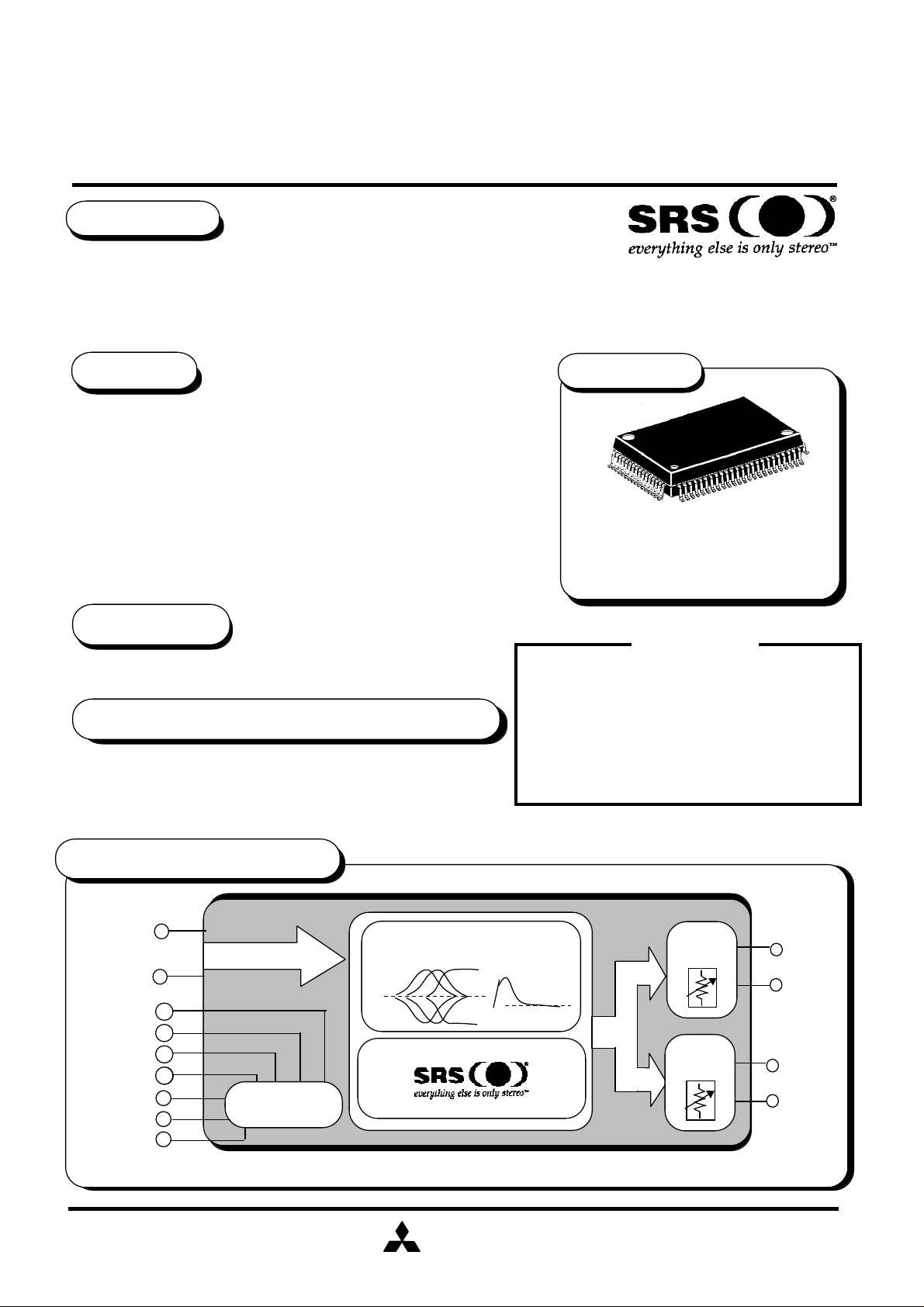
M62430FP
DESCRIPTION
The M62430FP is dual channel sound volume/quality.
The volume section is designed to the 2 channel either simultaneously or respectively in
steps of 1dB. It incorporates the ladder resistance mechanism to reduce noise and distortion.
The tone control section is capable of controlling the tone within ±10dB in steps of 2dB.
The M62430FP is built in Sound Retrieval System.
FEATURES
• Electric volume (MAIN and REC Volume )
•Volume level........... 0dB ~ -79dB,- ∞dB (1dB / step)
• Tone control
•Bass / Mid / Treble , 0dB ~ ±10dB(2dB / step)
•Bass boost +10dB(ON / OFF)
• SRS Surround
• Space/Center volume ... 0dB ~ -∞dB
• 4 Output ports
• Built-in microcomputer interface circuit controlled by 16-bit serial
data.
PACKAGE
Outline
0.8mm Pitch QFP
(20.0 mmx14.0mmx2.8mm)
80P6N-A
APPLICATION
Home Audio equipment,Radio-Cassette tape recorder,TV
RECOMMENDED OPERATING CONDITIONS
Supply voltage range.....9.0 ~ 14.6V (analog)
4.5 ~ 5.5V (digital)
Rated supply voltage ..... 14.0V (analog)
5.0V (digital)
SYSTEM BLOCK DIAGRAM
IN 2A
IN 1A
PORT1
PORT2
PORT3
PORT4
LATCH
DATA
CLK
µ-com Interface
Tone
control
Bass boost
&
SRS,the SRS logo,Sound Retrieval System and
"everything else is only stereo" are registered trademarks
of SRS Labs, Inc.
This device available only to licensees of SRS
Lab,Inc. Licensing and application information
may be obtained from SRS Lab, Inc.
Mitsubishi Electric Corporation assumes no responsibility
for any damage,or infringement of any third-party's rights,
originating in the use of any product data, diagrams, charts
or circuit application examples contained in these
materials.
Note !!
Main
volume
Rec
volume
MAIN
OUT 2
MAIN
OUT1
REC
OUT 2
REC
OUT1
D-62430-59E
MITSUBISHI
ELECTRIC
( / 17 )
1
Page 2
MITSUBISHI SOUND PROCESSORS
PRELIMINARY
M62430FP
Notice ; This is not a final specification.
some parametric limits are subject to change.
DIGITAL SOUND CONTROLLER WITH SRSsurround
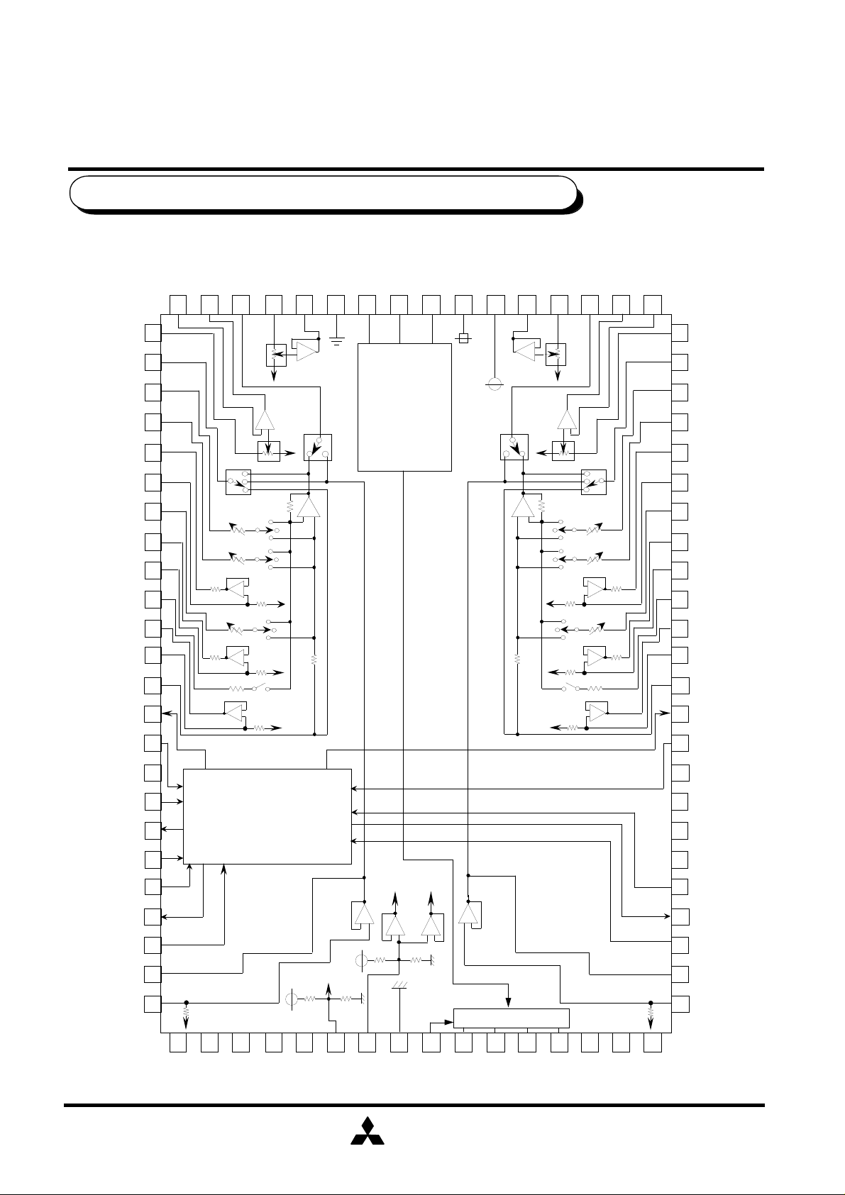
PIN CONFIGURATION AND IC INTERNAL BLOCK DIAGRAM
RECINP2
SELOUT2
T2R3
T2R2
T2O2
T2I2
T2R1
T2O1
T2I1
BBR2
BBO2
BBI2
TONEIN2
SUROUT2
SURIN2-2
RECOUT 2
RECINN 2
TONEOUT 2
VOLOUT 2
VOLIN 2
40 39 38 37 36 35 34 33 32 31 30 29 28 27 26 25
4142
+
43
TONE
444546
4748
49
50
REC
SELECT
-
+
T
N
S
12K
+
150K
PASS
0
-
+
51
-
52
+
150K
12K
53
-
5455
+
150K
DGND
1
LATCH
DATA
MICROCOMPUTER
INTERFACE
DVDD
CLOCK
AVDD
TONE
PASS
VOLOUT 1
+
01
+
-
12K
VOLIN 1
+
-
12K
150K
150K
150K
TONEOUT1
T
N
S
REC
SELECT
+
+
-
+
RECOUT 1
RECINN 1
24
RECINP 1
SELOUT1
23
T1R3
22
T1R2
21
T1O2
20
T1I2
19
T1R1
T1O1
17 18
T1I1
BBR1
15 16
BBO1
14
BBI1
TONEIN1
12 13
SUROUT1
11
SURIN1-2
NC5
SURS
SOUT
SIN2
SIN1
SUROUT2-1
SURIN2
OUT2A
IN2A
56
57
OUT2-2
OUT2-2
58
IN1
SRS
30K 30K
ch1ch2
-
+
30K
+
-
+
30K
59
60
61
6263
64
100K
IN2
SRS
SURROUND
65 66 67 68 69 70 71 72 73 74
NC6
NC7
NC8
NC9
NC10
REFIN1
AVss
REFIN2
MITSUBISHI
ELECTRIC
+
-
-
PORT OUTPUT
VDDP
PORT1
75 76
PORT2
77
PORT3
78
NC12
PORT4
100K
79 80
NC13
9 10
NC4
8
NC3
7
NC2
6
NC1
5
SURC
4
SUROUT1+2
3
SURIN1
2
OUT1A
1
IN1A
NC14
( / 17 )
2
Page 3

MITSUBISHI SOUND PROCESSORS
PRELIMINARY
Notice ; This is not a final specification.
some parametric limits are subject to change.
ABSOLUTE MAXIMUM RATINGS
Symbol
VDD
Pd
K
Topr
Tstg
Operating temperature
Parameter Conditions Ratings Unit
Supply Voltage
Power dissipation
Thermal derating
Storage temperature
DIGITAL SOUND CONTROLLER WITH SRSsurround
Ta≤25°C
Ta>25°C
*standard board
M62430FP
16.0
1.25
12.5
-20 ~+55
-55 ~+125
mW/°C
V
W
°C
°C
THERMAL DERATING
(MAXIMUM RATING)
1.5
1.25W
1.0
0.875W
0.5
POWER DISSIPATION pd [W]
0
0
25 50 75 100
AMBIENT TEMPERATURE Ta [°C]
55
125
*Standard board
•board size 140mmx140mm
•board thickness 1.6mm
•board material glass epoxy
•copper pattern
copper thickness 18 µm
copper size 0.25mm(width)
50mm (length/lead)
150
MITSUBISHI
ELECTRIC
( / 17 )
3
Page 4
MITSUBISHI SOUND PROCESSORS
PRELIMINARY
Notice ; This is not a final specification.
some parametric limits are subject to change.
RECOMMENDED OPERATING CONDITION
Parameter Symbol Condition
Analog
Supply Voltage
PORT
Supply Voltage
Digital
AVDD
VDDP
DVDD
Supply Voltage
DIGITAL SOUND CONTROLLER WITH SRSsurround
M62430FP
MIN TYP
9.0
4.5
4.5
14.0
5.0AVDD≥VDDP
5.0
MAX
14.6
14.6
5.5
Unit
V
V
V
High-level Input
VIH
DVDD-0.7
Voltage
Low-level Input
Voltage
VIL
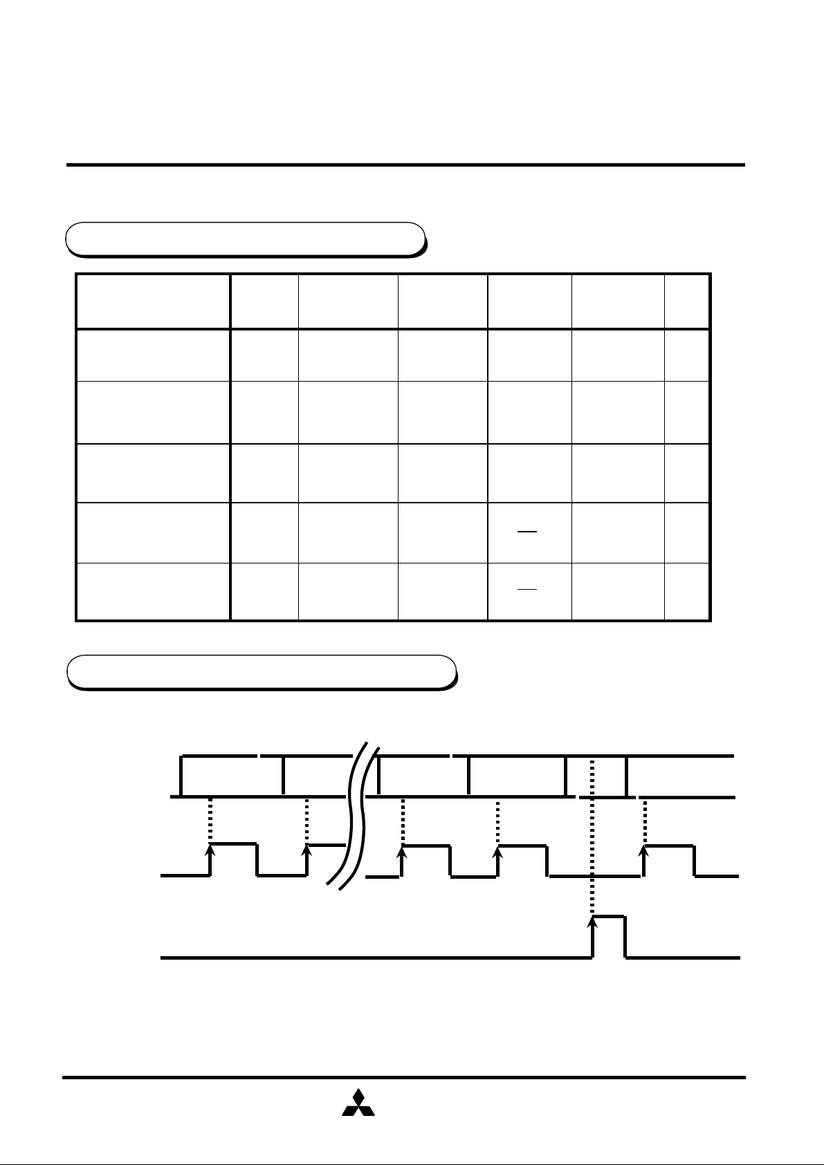
DATA TIMING (Recommended conditions)
H
DATA
CLOCK
LATCH
D0
L
H
L
H
D1
DVDD
0 V
DGND+0.7
DFDE
V
D0
L
note : CLOCK and LATCH function at raising edges of pulse .
MITSUBISHI
ELECTRIC
( / 17 )
4
Page 5
MITSUBISHI SOUND PROCESSORS
PRELIMINARY
Notice ; This is not a final specification.
some parametric limits are subject to change.
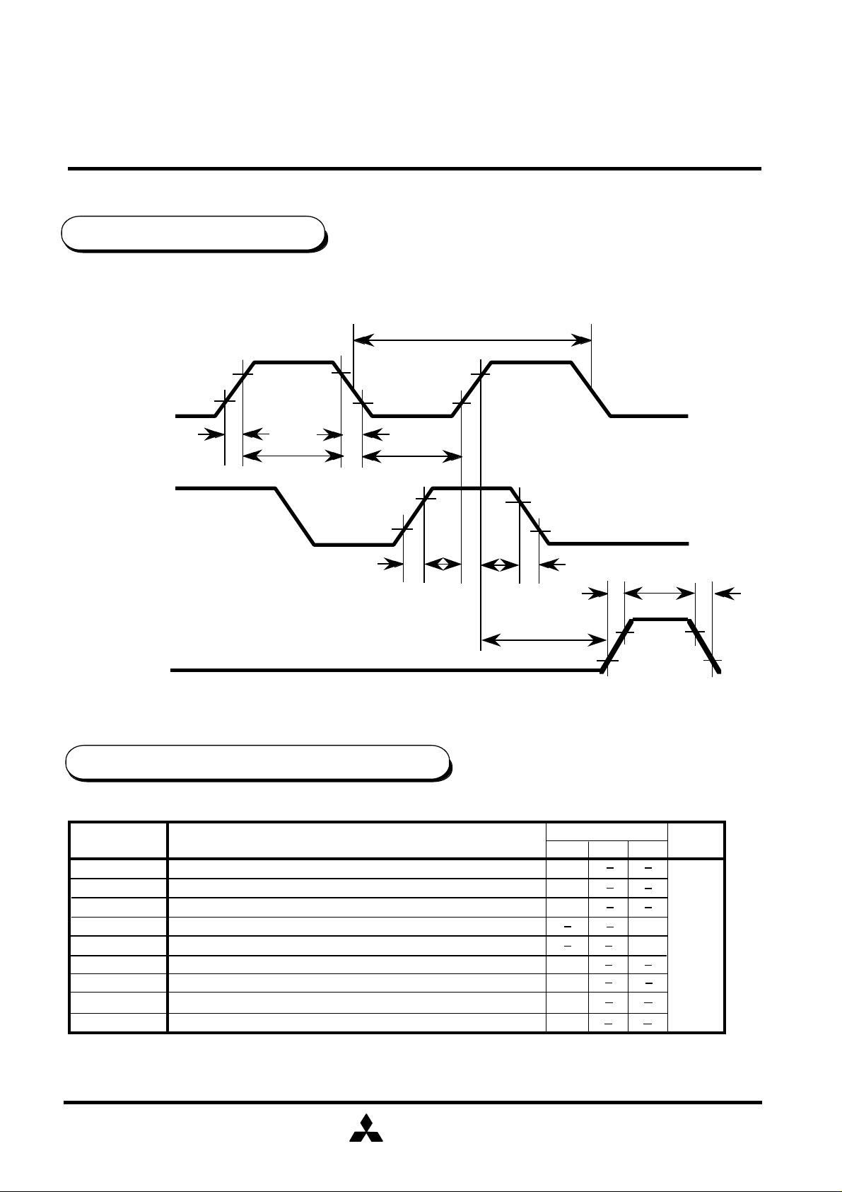
CLOCK, DATA,LATCH TIMING
CLOCK
DATA
75%
25%
tr
tWHC
M62430FP
DIGITAL SOUND CONTROLLER WITH SRSsurround
cr
t
tf
WLC
t
75%
25%
tr
LATCH
DIGITAL BLOCK TIMING REGULATION
Symbol
tcr
tWHC
tWLC
r
t
tf
tSD
t
HD
tSL
tWHL
CLOCK cycle time
CLOCK pulse width ("H"level)
CLOCK pulse width ("L"level)
CLOCK,DATA,LATCH rise time
CLOCK,DATA,LATCH fall time
DATA setup time
DATA hold time
LATCH setup time
LATCH pulse width
Parameter
tSL
tf
tWHC
tr
tf
75%
25%
SD
t
HD
t
Limits
0.8
0.8
Unit
µsec
Min
8
3.2
3.2
1.6
1.6
2
3.2
typ
Max
MITSUBISHI
ELECTRIC
( / 17 )
5
Page 6
MITSUBISHI SOUND PROCESSORS
PRELIMINARY
M62430FP
Notice ; This is not a final specification.
some parametric limits are subject to change.
DIGITAL SOUND CONTROLLER WITH SRSsurround
DIGITAL CONTROL SPECIFICATION
Fore kinds of input format options are available by changing slot settings of DE and DF.
(When the IC is powered up , the internal settings are not fixed.)
(1)
(2)
DO1 D11 D21 D31 D41 D51 D61 D71
TONE
CONTROL
TREBLE
TONE
CONTROL
MID
DO2 D12 D22 D32 D42 D52 D62 D72
TONE
CONTROL
BASS
MAIN VOLUME CH 2
BASS
BOOST
1: ON
0: OFF
TONE
PASS
1: ON
0: OFF
DFDED81 D91 DA1 DB1 DC1 DD1
0 0
DFDED82 D92 DA2 DB2 DC2 DD2
0 1MAIN VOLUME CH 1
(3)
(4)
DO3 D13 D23 D33 D43 D53 D63 D73
REC VOLUME CH 1
DO4 D14 D24 D34 D44 D54 D64 D74
SRS
"Space"
VOLUME
&
"Center"
VOLUME
SURROUND
1: ON
0: OFF
REC VOLUME CH 2
REC
SELEC
PORT1
1:H
0:L
TOR
PORT2
1:H
0:L
PORT3
1:H
0:L
PORT4
1:H
0:L
DFDED83 D93 DA3 DB3 DC3 DD3
01
DFDED84 D94 DA4 DB4 DC4 DD4
11
MITSUBISHI
ELECTRIC
( / 17 )
6
Page 7

MITSUBISHI SOUND PROCESSORS
PRELIMINARY
Notice ; This is not a final specification.
some parametric limits are subject to change.
SETTING CODE
(1) Tone control (bass / mid / treble)
D01 D11 D21 D31
D41 D51 D61 D71
D81 D91 DA1 DB1
1 1 1 0
1 1 0 0
1 0 1 1
1 0 1 0
1 0 0 1
0 0 0 0
0 0 0 1
0 0 1 0
0 0 1 1
0 1 0 0
0 1 1 0
ATT
- 10dB
- 8dB
- 6dB
- 4dB
- 2dB
+ 0dB
+ 2dB
+ 4dB
+ 6dB
+ 8dB
+ 10dB
treble
mid
bass
DIGITAL SOUND CONTROLLER WITH SRSsurround
M62430FP
(4) Port output
DA4 DB4 DC4 DD4
L
PORT1
PORT2
PORT3
PORT4
0
H
1
0
-
1
0
-
1
0
-
1
(5) Surround control
("Space"vol / "Center"vol)
- - -
L
-
- -
-
L
H
H
-
-
L
H
(2) Bass boost
ATT
+ 0dB 0
+10dB 1
DC1
(3) REC selector
D84 D94
normal
surround
tone
0 0
0
1
"S"vol
ATT
"C"vol
0dB
-3dB
-6dB
-9dB
-12dB
-15dB
-18dB
-21dB
1
0
Note : Do not input other data than the above.
D04 D14 D24
D34 D44 D54
000
0
0
0
0
1
1
1
1
0
1
1
1
0
0
0
1
0
1
1
11
111-∞dB
D64
X
X
X
X
X
X
X
0
1
MITSUBISHI
ELECTRIC
( / 17 )
7
Page 8

MITSUBISHI SOUND PROCESSORS
PRELIMINARY
Notice ; This is not a final specification.
some parametric limits are subject to change.
(6)-1 MAIN VOLUME / REC VOLUME ( 0~ -39dB)
MAIN VOLUME
CH 1
MAIN VOLUME
A
CH 2
T
REC VOLUME
CH 1
T
REC VOLUME
CH 2
-0dB
-1dB
-2dB
-3dB
-4dB
-5dB
-6dB
-7dB
-8dB
-9dB
-10dB
-11dB
-12dB
-13dB
-14dB
-15dB
-16dB
-17dB
-18dB
-19dB
-20dB
-21dB
-22dB
-23dB
-24dB
-25dB
-26dB
-27dB
-28dB
-29dB
-30dB
-31dB
-32dB
-33dB
-34dB
-35dB
-36dB
-37dB
-38dB
-39dB
DIGITAL SOUND CONTROLLER WITH SRSsurround
D02 D12
D72 D82
D03 D13
D73 D83
0 0
0 0
0
0
0
0
0 0
0 0
0 0
0 0
0
0
0
0
0 0
0 0
0 0
0 0
0
0
0
0
0 0
0 0
0 0
0 0
0
0
0
0
0 0
0 0
0 1
0 1
0
0
0
0
0 1
0 1
M62430FP
Note : Do not input other data than the above.
D22
D92
D23
D93
D32
DA2
D33
DA3
0
0
0
0
0
0
0
0
0
0
0
0
0
0
0
0
0
0
0
0
0
0
0
0
1
1
0
0
0
0
1
1
1
1
1
1
1
1
0
0
0
0
1
1
1
1
1
1
0
0
1
1
1
1
0
0
0
0
0
0
D42
DB2
D43
DB3
0
0
0
0
0
0
0
0
1
1
1
1
1
1
1
1
0
0
0
0
0
0
0
0
1
1
1
1
1
1
1
1
0
0
0
0
0
0
0
0
D52
DC2
D53
DC3
0
0
0
0
1
1
1
1
0
0
0
0
1
1
1
1
0
0
0
0
1
1
1
1
0
0
0
0
1
1
1
1
0
0
0
0
1
1
1
1
D62
DD2
D63
DD3
0
0
1
1
0
0
1
1
0
0
1
1
0
0
1
1
0
0
1
1
0
0
1
1
0
0
1
1
0
0
1
1
0
0
1
1
0
0
1
1
0
1
0
1
0
1
0
1
0
1
0
1
0
1
0
1
0
1
0
1
0
1
0
1
0
1
0
1
0
1
0
1
0
1
0
1
0
1
0
1
MITSUBISHI
ELECTRIC
( / 17 )
8
Page 9

MITSUBISHI SOUND PROCESSORS
PRELIMINARY
Notice ; This is not a final specification.
some parametric limits are subject to change.
(6)-2 MAIN VOLUME / REC VOLUME ( -40~ - ∞dB)
MAIN VOLUME
CH 1
MAIN VOLUME
A
CH 2
T
REC VOLUME
CH 1
T
REC VOLUME
CH 2
-40dB
-41dB
-42dB
-43dB
-44dB
-45dB
-46dB
-47dB
-48dB
-49dB
-50dB
-51dB
-52dB
-53dB
-54dB
-55dB
-56dB
-57dB
-58dB
-59dB
-60dB
-61dB
-62dB
-63dB
-64dB
-65dB
-66dB
-67dB
-68dB
-69dB
-70dB
-71dB
-72dB
-73dB
-74dB
-75dB
-76dB
-77dB
-78dB
-79dB
-∞dB
DIGITAL SOUND CONTROLLER WITH SRSsurround
Note : Do not input other data than the above.
D02 D12
D72 D82
D03 D13
D73 D83
0 1
0 1
0
0
0
0
0 1
0 1
0 1
0 1
0
0
0
0
0 1
0 1
0 1
0 1
0
0
0
0
0 1
0 1
1 0
1 0
1
1
1
1
1 0
1 0
1 0
1 0
1
1
1
1
1 0
1 0
1
D22
D92
D23
D93
D32
DA2
D33
DA3
0
0
1
1
1
1
0
0
0
0
0
0
1
1
1
1
1
1
1
1
1
1
1
1
1
1
1
1
1
1
1
1
1
1
1
1
0
0
0
0
0
0
0
0
0
0
0
0
0
0
0
0
0
0
0
0
0
0
0
0
1
D42
DB2
D43
DB3
1
1
1
1
1
1
1
1
0
0
0
0
0
0
0
0
1
1
1
1
1
1
1
1
0
0
0
0
0
0
0
0
1
1
1
1
1
1
1
1
0 0 0 00
M62430FP
D52
DC2
D53
DC3
0
0
0
0
1
1
1
1
0
0
0
0
1
1
1
1
0
0
0
0
1
1
1
1
0
0
0
0
1
1
1
1
0
0
0
0
1
1
1
1
D62
DD2
D63
DD3
0
0
1
1
0
0
1
1
0
0
1
1
0
0
1
1
0
0
1
1
0
0
1
1
0
0
1
1
0
0
1
1
0
0
1
1
0
0
1
1
0
1
0
1
0
1
0
1
0
1
0
1
0
1
0
1
0
1
0
1
0
1
0
1
0
1
0
1
0
1
0
1
0
1
0
1
0
1
0
1
MITSUBISHI
ELECTRIC
( / 17 )
9
Page 10

MITSUBISHI SOUND PROCESSORS
PRELIMINARY
Notice ; This is not a final specification.
some parametric limits are subject to change.
ELECTRICAL CHARACTERISTICS
(Ta=25°C, AVDD=14.0V , DVDD=5.0V , f=1kHz, unless otherwise noted.
TONE CONTROL , BASS BOOST , VOLUME are set to 0dB )
(1) Power supply characteristics
Analog circuit current
Digital circuit current
(2) Input / Output characteristics
Parameter
Input resistance
Maximum output voltage
Pass gain
Distortion factor
DIGITAL SOUND CONTROLLER WITH SRSsurround
AIdd
DIdd
Symbol
Rin
VOM
Gv
THD
THDrecA
M62430FP
Test conditions
Current at pin 30
No signal
Current at pin 31
No signal
Test conditions
1pin,64pin,Ta=25°C
Input to pin1,64,Output from
pin29,36
RL =10KΩ,THD=1%
Vi=0.2Vrms, flat , pin1,64 - 29,36
gains
Pin29,36, BW=400~30kHz
Vi=0.2Vrms , RL=10KΩ
Pin26,39, BW=400~30kHz
Vi=0.2Vrms , RL=30KΩ
Limits
Min
Min
typ
45 mA
0.3 mA
Limits
typ
100 KΩ
4.0 Vrms3.0
0
Max
60
1.2
Max
15050
2.0-2.0
0.090.003
0.070.003
UnitSymbolParameter
Unit
dB
%
%
Output noise voltage
Crosstalk between channels
THDrecB
THDrecC
Vono
Vonop
VrecnoA
VrecnoB
VrecnoC
CT
CTrec
recA : SELECTOR OUT
recB : SURROUND OUT
recC : TONE OUT
Pin29,36,Rg=10KΩ,JIS-A,
VOL=0dB
Pin29,36,Rg=10KΩ,JIS-A,
PASS MODE,VOL=MIN
Pin26,39,Rg=10KΩ,JIS-A,
VOL=0dB
recnoA : SELECTOR OUT
recnoB : SURROUND OUT
recnoC : TONE OUT
Vo=0.5Vrms , RL=10KΩ,JIS-A
Between pin29-36 RL=10KΩ
Vo=0.5Vrms , RL=30KΩ,JIS-A
Between pin26-39 RL=10KΩ
MITSUBISHI
ELECTRIC
0.005
10
3 µVrms6
4 10
8 18
10
-80 -65
-80 -65
0.09
24
24
( / 17 )
10
%
µVrms
µVrms
µVrms
µVrms
dB
dB
Page 11

MITSUBISHI SOUND PROCESSORS
PRELIMINARY
Notice ; This is not a final specification.
some parametric limits are subject to change.
(3) Tone control characteristics
Tone control voltage gain
DIGITAL SOUND CONTROLLER WITH SRSsurround
SymbolParameter Test condition
T -10dB -10-12 -8
T - 6dB
T - 4dB
T - 2dB
T+2dB
M62430FP
Vo=0.2Vrms,f=1kHz
TLEBLE,MID,BASS
Input pin12,53 -29,36 gains
Min
-7.5
1
Limits
typ
-8T - 8dB -10 -6
-6
-4.5
-4-5.5 -2.5
-2-3 -1
2
Max
3
Unit
dB
dB
dB
dB
dB
dB
Bass boost voltage gain
Balance between channel
(4) Port
Port output
T+4dB
T+6dB
T+8dB
T+10dB
BB10dB
BALT 0 +1.5-1.5
f=100Hz,Vo=0.2Vrms
Input pin12,53 -29,36 gains
Input pin12,53 Vo=0.2Vrms
Output pin23,42,
boost condition +10,-10dB
4.5
SymbolParameter Test condition
Min
Vport
RL=20KΩ
VDDP2=5V
2.5
4
5.5
6
7.5
8
6 10
10
8
8 12 dB
Limits
10
typ
4.94.0
12
Max
Unit
dB
dB
dB
dB
dB
V
MITSUBISHI
ELECTRIC
( / 17 )
11
Page 12

MITSUBISHI SOUND PROCESSORS
PRELIMINARY
Notice ; This is not a final specification.
some parametric limits are subject to change.
DIGITAL SOUND CONTROLLER WITH SRSsurround
(5) SRSSurround characteristics
SymbolParameter Test condition
Feed through gain
By-pass gain
L (2)- R(1) gain
L(2) + R(1) gain
( R:ch1 , L:ch2 , MAX:0dB , MIN:-∞dB )
Gvsrsf
Gvsrsb
GvsrsL-R
GvsrsL+R
SRS Block
M62430FP
(Vi=500mVrms,f=1kHz, unless otherwise noted.)
"S" VOL : MIN "C" VOL : MIN
Input : pin3,62 Output : pin11,54
SRS OFF
Input : pin3,62 Output : pin11,54
"S" VOL : MAX
Input : pin62 Output : pin54
"S" VOL : MIN
Input : pin62 Output : pin54
"C" VOL : MIN
"C" VOL : MAX
Min
-12.5
-2.0
9.6
-8.0
Limits
typ
-10.5
0
11.6
-6.0
Max
-8.5
+2.0
13.6
-4.0
Unit
dB
dB
dB
dB
SURIN2
(pin62)
SUROUT2
(pin54)
SRS surround
SURIN1
(pin3)
Note:
SRS,the SRS logo,Sound Retrieval System and "everything else is only stereo" are registered trademarks of SRS Labs, Inc.
This device available only to licensees of SRSLab,Inc. Licensing and application information
may be obtained from SRS Lab, Inc.
Please be advised that those customers intending to adopt the products described in this specification are required to obtain a license
under a separate license agreement with SRS LABS,INCORPORATED("SRS") in order to utilize the products containing SRS's
intellectual property.
Purchase of this product does not convey the right to sell recordings made with the Sound Retrieval System .
SUROUT1
(pin11)
MITSUBISHI
ELECTRIC
( / 17 )
12
Page 13

MITSUBISHI SOUND PROCESSORS
PRELIMINARY
Notice ; This is not a final specification.
some parametric limits are subject to change.
-
+
Tone control
+10dB ~ -10dB
12KΩ
BASS
BOOST
12KΩ
MID
BASS
DIGITAL SOUND CONTROLLER WITH SRSsurround
TLEBLE
150K
4700pF
M62430FP
-
+
MAIN VOLUME (0dB ~ - ∞dB)
VOL
IN 2
3.3µ F
VOL
OUT 2
3.3µ F
TONE
IN2
SUR
OUT2
SRS BLOCK
SRS
SUR IN2
3.3µ F
SURROUND
2.2µ F
OUT2A
"Center"
(0dB ~ -∞dB)
"Space"
(0dB ~ -∞dB)
SRS
ON/OFF
100KΩ
1µ F
0
1
TONE PASS
REC
OUT 2
3.3µ F
T
S
N
REC SELECT
-
+
REC
INN 2
REC
INP 2
REC VOLUME (0dB ~ - ∞dB)
3.3µ F
-
+
SELOUT2
SYSTEM DIAGRAM 1. ( 1st SIDE )
IN2A
MITSUBISHI
ELECTRIC
( / 17 )
13
Page 14

MITSUBISHI SOUND PROCESSORS
PRELIMINARY
Notice ; This is not a final specification.
some parametric limits are subject to change.
-
+
Tone control
+10dB ~ -10dB
12KΩ
TONE IN2
BASS
3.3µF
OUT2A
DIGITAL SOUND CONTROLLER WITH SRSsurround
12KΩ
TLEBLE
MID
BASS
BOOST
1
0
TONE PASS
M62430FP
-
+
MAIN VOLUME (0dB ~ - ∞dB)
-
+
3.3µ F
VOL
VOL
IN 2
OUT 2
REC
REC
OUT 2
INN 2
3.3µ F
3.3µ F
-
+
100KΩ
1µ F
SYSTEM DIAGRAM 2.( 1st SIDE )
IN2A
REC SELECT
SRS BLOCK
SRS
T
S
N
SURROUND
REC VOLUME (0dB ~ - ∞dB)
"Center"
"Space"
(0dB ~ -∞dB) (0dB ~ -∞dB)
SRS
ON/OFF
REC
INP 2
3.3µ F
SUR OUT2
SELOUT2
3.3µF
MITSUBISHI
ELECTRIC
SUR IN2
( / 17 )
14
Page 15

MITSUBISHI SOUND PROCESSORS
PRELIMINARY
Notice ; This is not a final specification.
some parametric limits are subject to change.
RECOUT 2
40 39 38 37 36
Units Resistance : Ω
Capacitance : F
41
3.3µ
42
4700P
43
44
454647
820P 0.1µ
48
DIGITAL SOUND CONTROLLER WITH SRSsurround
VOLOUT 2
-
+
T
N
S
REC
SELECT
12K
+
-
+
DigitalGND
35 34
TONE
PASS
10
M62430FP
VOLOUT 1
5V
MCU
Analog14V
33 32 31 30 29 28 27 26 25
-
+
TONE
PASS
MICROCOMPUTER
INTERFACE
0
1
12K
+
-
3.3µ3.3µ
+
-
T
N
S
REC
SELEC
T
RECOUT 1
24
3.3µ
4700P
820P 0.1µ
0.0056µ 0.82µ
0.01µ 1µ
(1)Single power supply specification
3.3µ
APPLICATION EXAMPLE
SURIN
49
5051
52
53
5455
+
150K
+
150K
+
150K
2-2
31.6K
1.5K
0.47µ
3.74K
47K
0.0047µ
4.3K
NC5
110K
0.47µ
5657
OUT2-2
4.7µ
5859
IN2
6061
1K 120K
62
2.2µ
6364
+
100K
1µ
65 66 67 68 69 70 71 73 74 75 76 77 78 79 80
65 66 67 68 69 70 71 72 73 74
NC6
NC7
NC8
12K
SRS
SURROUND
30K 30K
NC9
NC10
OUT1-2
SRS
+
IN1
-
+
+
100µ
30K
-
10µ
+
30K
ch1ch2
+
-
VDDP
12K
+
-
PORT OUTPUT
75 76
20K
20K
20K
V2 V3 V4
V1
150K
150K
150K
77
20K
78
+
+
+
79 80
NC11
100K
NC12
NC13
16 17 18 19 20 21 22 23
15
14
11 12 13
SURIN
10
1-2
9
NC4
NC3
7 8
NC2
6
NC1
5
4
3
2
1
+
1µ
0.0056µ 0.82µ
0.01µ 1µ
3.3µ
4.7µ
2.2µ
MITSUBISHI
ELECTRIC
( / 17 )
15
Page 16

MITSUBISHI SOUND PROCESSORS
PRELIMINARY
Notice ; This is not a final specification.
some parametric limits are subject to change.
RECOUT 2
40 39 38 37 36
Units Resistance : Ω
Capacitance : F
41
3.3µ
42
4700P
43
444546
820P 0.1µ
4748
DIGITAL SOUND CONTROLLER WITH SRSsurround
VOLOUT 2
-
+
T
N
S
REC
SELECT
12K
MCU
DigitalGND
35 34
+
TONE
PASS
10 01
-
+
33 32 31 30 29 28 27 26 25
MICROCOMPUTER
INTERFACE
M62430FP
5V
VOLOUT 1
Analog+7V
-
+
TONE
PASS
+
-
12K
3.3µ3.3µ
+
-
T
N
S
REC
SELEC
T
RECOUT 1
22 23 24
21
20
19
17 18
3.3µ
4700P
820P 0.1µ
0.0056µ0.82µ
49
50
51
(2)2 power supply specification
APPLICATION EXAMPLE
0.01µ 1µ
3.3µ
SURIN
2-2
NC5
47K
31.6K
110K
1.5K
0.0047µ
4.3K
0.47µ
3.74K
0.47µ
52
53
5455
5657
OUT2-2
4.7µ
5859
121K
60
1K
61
62
2.2µ
63
+
64
100K
1µ
65 66 67 68 69 70 71 72 74 75 76 77 78 79 80
IN2
+
+
+
150K
150K
150K
SRS
12K
OUT1-2
30K
SRS
IN1
30K
SURROUND
150K
+
15 16
0.0056µ 0.82µ
14
12K
150K
+
0.01µ 1µ
12 13
+
150K
10 11
9
8
7
6
ch1ch2
+
-
+
30K
+
-
+
30K
-
-
5
4
3
2
1
PORT OUTPUT
100K
3.3µ
SURIN
1-2
NC4
NC3
NC2
NC1
4.7µ
2.2µ
+
1µ
73
NC6
NC7
NC8
NC9
NC10
VDDP
Analog-7V
MITSUBISHI
ELECTRIC
20K
20K
V2 V3 V4
V1
20K
20K
NC13
NC12
( / 17 )
16
NC14
Page 17

MITSUBISHI SOUND PROCESSORS
PRELIMINARY
Notice ; This is not a final specification.
some parametric limits are subject to change.
Keep safety first in your circuit designs !
• Mitsubishi Electric Corporation puts the maximum effort into making
semiconductor products better and more reliable, but there is always the
possibility that trouble may occur with them.Trouble with semiconductors
may lead to personal injury, fire or property damage. Remember to give due
consideration to safety when making your circuit designs, in order to
prevent fires from spreading, redundancy, malfunction or other mishap.
DIGITAL SOUND CONTROLLER WITH SRSsurround
M62430FP
Notes regarding these materials
• These materials are intended as a reference to assist our customers in the
selection of the Mitsubishi semiconductor product best suited to the
customer's application; they do not convey any license under any
intellectual property rights, or any other rights, belonging to Mitsubishi
Electric Corporation or a third party.
• Mitsubishi Electric Corporation assumes no responsibility for any damage,
or infringement of any third-party's rights, originating in the use of any
product data, diagrams, charts or circuit application examples contained in
these materials.
• If these products or technologies are subject to the Japanese export
control restrictions, they must be exported under a license from the
Japanese government and cannot be imported into a country other than
the approved destination.
Any diversion or reexport contrary to the export control laws and
regulations of Japan and/or the country of destination is prohibited.
MITSUBISHI
ELECTRIC
( / 17 )
17
 Loading...