

Page 1
MITSUBISHI <CONTROL / DRIVER IC>
M54687FP
Bi-DIRECTIONAL MOTOR DRIVER WITH GOVERNOR
DESCRIPTION
The M54687FP is a semiconductor integrated circuit that is
capable of directly controlling the rotating direction and rotating
speed of a smallsize bi-directional motor rotating in both forward
and reverse directions.
FEATURES
● Capable of controlling the speed in forward and reverse rotating
directions
● Capable of controlling the speed in high speed mode
● Large output current drive (IO(max) =700mA)
● Built-in clamp diode
● Flat package (16P2N )
APPLICATION
Micro-cassette for phone-answering machine, AV equipment, and
other general consumption appliances
FUNCTION
The M54687FP is an IC that can control the forward rotation,
reverse rotation and speed of small DC brush motor.
For the basic operation of this IC, output modes are selected, as
shown in the logic truth table, by entering appropriate H/L level into
the R, L and S inputs.
Two resistances are put between the output pin and the PSC pin
and the resistance ratios are appropriately adjusted to perform the
speed control.
In addition to the above, speed control can be done by varying the
voltage at VR pin, in the high speed mode.
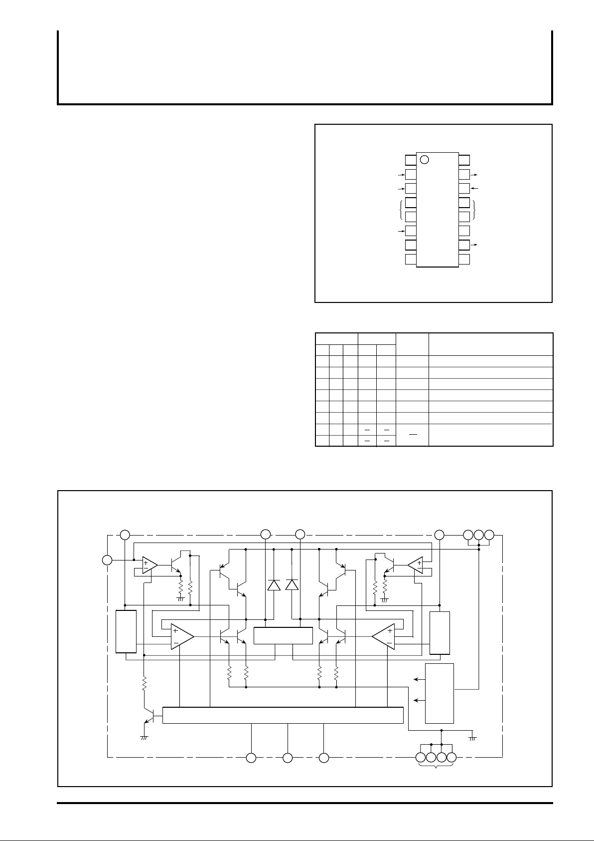
PIN CONFIGURATION (TOP VIEW)
R input
S input
L input
PSC1
GND
L-V
PSC2
R
S
L
CC
1
2
M54687FP
3
4
6
7
Outline 16P2N-A
16
15
14
13
125
11
10
98
Speed control 1
Power supply
LOGIC TRUTH TABLE
Input
L
R
H
H
L
H
H
L
L
L
H
H
L
L
L
H
H
L
G: Governor control output mode
FG: Rotating speed controllable with the voltage at V
precision is worse than G.)
Output
S
O1
H
H
H
H
H
FG
H
G
L
L
OFF
L
L
L
O2
FG
G
H
H
L
OFF
Mode
FF
PLAY
REW
REV
BRAKE
STB
Forward rotation high speed governor
Forward rotation governor
Reverse rotation high speed governor
Reverse rotation governor
Brake operation
Standby mode output high imp.
Reserved
Power supply
P-VCC
O1
Output 1
High speed
VR
control
GND
NC
O
2
Output 2
P-VCC
Power supplySpeed control 2
NC: no connection
R pin (However, the
BLOCK DIAGRAM
Speed control 1
PSC1
14
1
voltage
Reference
High Speed
control
VR
( – )
Output 1
RL S
R input L input S input
Output 2
O
1
O2
15 10
Activation circuit
Control circuit
362
( – )
Speed control 2
PSC2
8 7
voltage
Reference
Constant voltage,
Constant current
13
4 5 12
GND
Power supply
V
CC
9
16
Page 2

MITSUBISHI <CONTROL / DRIVER IC>
Bi-DIRECTIONAL MOTOR DRIVER WITH GOVERNOR
ABSOLUTE MAXIMUM RATINGS ( Ta=25°C, unless otherwise noted )
Symbol
VCC
VI
VO
IOP
I
O
P
d
opr
T
T
stg
Parameter
Supply voltage
Input voltage
Output voltage
Allowable motor rush current
Continuous output current
Power dissipation
Operating temperature
Storage temperature
ON 100ms, duty of 1% or less.
t
However, Pd must not exceed the maximum rating.
When mounted in board
Conditions
RECOMMENDED OPERATING CONDITION ( Ta=25˚C, unless otherwise noted)
Symbol
VCC
VIH “H” input voltage
V
IL “L” input voltage
V
R
IO 200mA when FF/REW speed is controlled.
∗
Supply voltage 6.0
VR control voltage range∗
Parameter
Min.
2.0
0
Limits
Typ.
9.0 13.0
Max.
VCC
0.4
VCC
Unit
V
V
V
V0
M54687FP
Ratings
– +14
-0.5
-0.5
– VCC
-0.5
– VCC+2
±700
±200
1.14
-20
– 75
-40
– 125
Unit
V
V
V
mA
mA
W
˚C
˚C
Page 3

MITSUBISHI <CONTROL / DRIVER IC>
/
/
/
/
/
/
/
/
/
Bi-DIRECTIONAL MOTOR DRIVER WITH GOVERNOR
ELECTRICAL CHARACTERISTICS ( Ta=25°C, unless otherwise noted )
Symbol Test conditions UnitParameter
V
I
O(leak)
II
VOH
VOL
ICC1
ICC2
ICC3
ICC4
Vref
IB
K
V
ref
Vref
K
K
Vref
Vref
K
K
Vref
Vref
K
K
ref II
V
Vref
Vref
Vref
Vref
ref
V
Vref
IB
IR
Output leak current
Input current
“H” output voltage
“L” output voltage
Supply
current
VCC
VCC
IO
IO
Ta
Ta
VCC
IO
Ta
VR input current
FF/REW
PLAY/REV
BRAKE
STAND BY
Reference voltage
Bias current
Current proportional constant
Voltage
characteristics
Current
characteristics
PLAY•REV mode
Governor characteristics (I)
Temperature
characteristics
Voltage
characteristics
Current
characteristics
(II) FF•REW
Bias current
Governor characteristics
Temperature
Reference voltage
characteristics
Vref
K
V
K
V
K
ref
ref
CC = 14V, VO = 14V
Standby mode
VI = 5.0V
IO = -200mA, VR = 5.0V
IO = 200mA, VR = 0V, Vpsc = 2.5V
FF / REW / BRAKE mode
Output open
Output open
Output open
O = 40mA
I
CC = 6.0 – 13V
V
CC = 6.0 – 13V
V
IO = 40mA
I
O = 50 – 200mA
IO = 50 – 200mA
T
a = -20 – 75˚C
a = -20 – 75˚C
T
R = 0.3V
V
R = 0.3V
V
VCC = 6.0 – 13V
V
R = 0.3V
IO = 50 – 200mA
R = 0.3V
V
Ta = -20 – 75˚C
VR = 0.3V
R = 0V
V
M54687FP
Limits
Min. Typ. Max.
0
0
V
CC-1.2
–
–
–
–
–
0.95
0.7
18
0.7
0
0.4
VCC-0.9
0.22
5.0
5.0
35
0
1.0
1.2
20
0.1
0.2
0.02
0.01
0.01
0.01
2.0
3.0
0.2
0.1
1.3
-5.0
100
1.0
–
0.5
8.0
8.0
48
10.0
1.05
1.7
22
1.8
-20
µA
mA
V
V
mA
mA
mA
µA
V
mA
–
%/V
%/V
%/mA
%/mA
%/˚C
%/˚C
V
%/V
%/mA
%/˚C
mA
µA
Page 4

APPLICATION EXAMPLE
• When the normal speed is set to 2000rpm, and the high speed
is set to 3500rpm
0.1µF
MITSUBISHI <CONTROL / DRIVER IC>
M54687FP
Bi-DIRECTIONAL MOTOR DRIVER WITH GOVERNOR
2k
RS
∗
V
CC = 9.0V
VCC = 5.0V
20k
1k
RT
300 / / 5.6 k
∗
M
O
2O1
PSC2
10µF
VCC
PSC1
RT
∗∗
∗
VR
∗
voltage
Reference
( – )
Activation circuit
Control circuit
( – )
voltage
Reference
Constant current
Constant voltage,
P-G
Motor: Armature resistance Ra = 14 , Generation constant Ka =
RT: The resistance of 300 is used for temperature compensation to take measures against hunting at low temperature.
R L S
Control signal
2.57
3000
Install at a position close to the IC, if possible.
∗
L-G
Page 5

Speed Control Method
(1) Speed Control Method I (See the application circuit drawing.)
For PLAY/REV
Rotation number can be expressed by the following formula:
1
N= {IB • RT+Vref
Ka
Where:
Motor generation constant: Ka, Motor armature resistance: Ra,
Rotation number: N
K: Current proportional constant, IB: PSC pin bias current,
Ia:motor current
RT, RS: External resistance
In addition, to set the rotation number with RS, external
resistance RT is generally set as follows:
RT K x Ra
For FF/REW
Note that the rotation number is basically controlled with the
same expression as formula (1) but different reference voltage
Vref and different bias current IB are to be used.
However, Vref 5VR+0.5
=
RT
(1+ )+la(
RT+RS
RT
K
-Ra)}
• • • • • • (1)
MITSUBISHI <CONTROL / DRIVER IC>
M54687FP
Bi-DIRECTIONAL MOTOR DRIVER WITH GOVERNOR
(3) Speed Control Method III (to increase the precision of forward
rotation and reverse rotation)
RT1RS1
RS2RT2
M
VCCVRPSC2PSC1 O1 O2
(2) Speed Control Method II (to increase the motor rotation number)
RS
RT RT
M
VRPSC2PSC1 O1 O2
R L S L-G P-G
Control signal
VCC
In the external circuit above, the voltage across motors is almost
determined by the ratio of ‘RS+RT’ to ‘RT’ and, therefore, a value
set for the voltage across motors is not so large.
As method (1) of speed control I, the rotation number can be
controlled.
However, the following relations must be satisfied:
RT RT+RS
RS+RT RT
R L S L-G P-G
Control signal
The above two applications cannot make fine adjustments in
forward rotation and reverse rotation (because the external
resistance is shared with the forward rotation and reverse rotation).
Fine adjustments can be made for each of forward rotation and
reverse rotation if the external circuit is set as shown in the drawing
above.
This external circuit is also available to change the speed of
forward and reverse rotation.
The control method adopts the same formula as formula (1).
However, the following relations must be satisfied:
RT+RS RS1 or RS2
RT RT1 or RT2
Page 6

MITSUBISHI <CONTROL / DRIVER IC>
CAUTIONS
M54687FP
Bi-DIRECTIONAL MOTOR DRIVER WITH GOVERNOR
(1) Oscillation may take place with the setting of RT>K•Ra. Set
(2) Add a capacitor of 0.1µF to the portion between PSCs to
(3) Add a capacitor of 10µF to the portion between VCC and GND
(4) At a low temperature, RT>K•Ra is set due to temperature
(5) When the supply voltage is low, note that saturation of the
When the back electromotive force is large with the brakes applied,
for example, malfunction may occur in internal parasitic Di. If
flyback current of 1A or more flows, add Schottky Di to the portion
between the output and the GND.
When the IC is used at a high speed for PWM etc., note that
switching of output results in delay of approx. 10µs.
•R K Ra.
reduce brush noise of the motor.
to reduce brush noise and back electromotive noise of the
motor.
characteristics of resistance Ra of the motor. When oscillation
takes place, use resistance with a temperature coefficient for
RT.
output transistor of the IC may prevent the rotating speed for
control. Taking into account motor noise etc., set constants in
the following range.
2.0V VCC - (EC+Ia • Ra)
= VCC - {RT • IB + Vref(1+ )+ • Ia}
RT
RS
RT
K
TYPICAL CHARACTERISTICS
Thermal Derating (Absolute Maximum Rating)
2.0
1.5
When mounted in board
1.0
Power Dissipation Pd (W)
0.5
0
0
25 50 75 100
Operating Temperature Ta (˚C)
 Loading...