

Page 1
MITSUBISHI ICs (Monitor)
M52722SP
3-CHANNEL VIDEO PREAMPLIFIER PROVIDED WITH OSD MIX
AND RETRACE LINE BLK FOR HIGH-RESOLUTION
DESCRIPTION
M52722SP is a video amplifier provided with OSD mixing function,
and a semiconductor IC having three channels of a built-in
wideband 180MHz amplifier.
Each channel has the functions of OSD blanking, OSD mixing,
retrace line blanking, wideband amplifier, main and sub contrast
control, and main brightness. Accordingly, it is structured to best fit
the OSD-provided high resolution display. .
FEATURES
P-P
P-P
P-P
P-P
(Typ.)
P-P
P-P
P-P
(max.)
(max.)
Frequency band : RGB...................................180MHz (at 3V
•
OSD....................................................50MHz
Input: RGB..........................................0.7V
OSD......................................more than 3V
(positive polarity)
BLK (for OSD)......................more than 3V
(positive polarity)
Retrace line BLK..................more than 3V
(positive polarity)
Output: RGB..........................................4.0V
OSD..........................................4.0V
Each control of contrast and OSD adjustment includes a main
•
which allows 3 channels to be variable simultaneously, and a sub
which allows each channel to be variable independently. Each
control pin can be controlled within a range of 0 to 5V.
A built-in feedback circuit inside IC provides a stable DC level at
•
IC output pins.
APPLICATION
CRT display
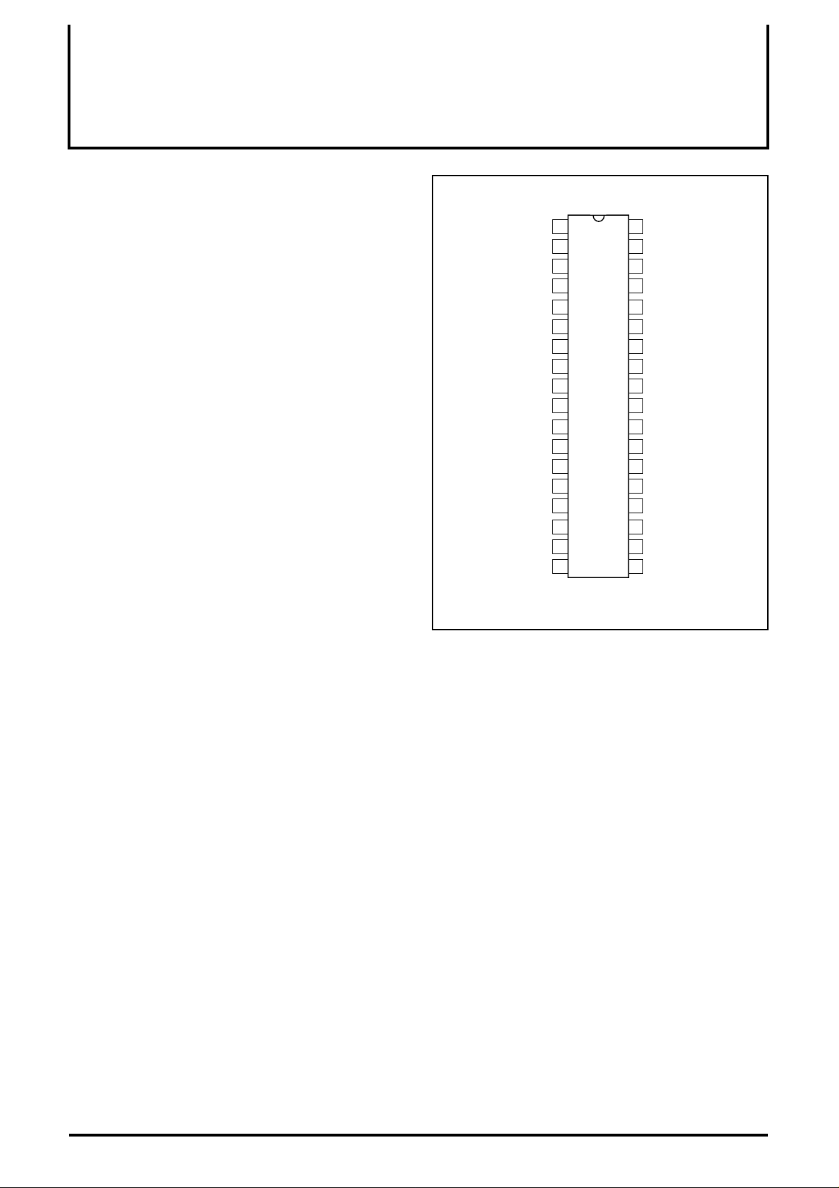
PIN CONFIGURATION (TOP VIEW)
CC1 (B)
CC1 (G)
CC1 (R)
CP IN
1
2
3
4
7
8
13
14
15 22
16 21
17
18 19
BLK IN(for OSD)
V
INPUT (B)
SUB CONTRAST (B)
OSD IN (B)
GND 1 (B)
V
)
SUB CONTRAST (G)
SUB CONTRAST (R)
INPUT (G)
OSD IN (G)
GND 1 (G)
V
INPUT (R)
OSD IN (R)
GND 1 (R)
MAIN CONTRAST
Outline 36P4E
36
35
34
33
325
316
30
M52722SP
29
289
2710
2611
2512
24
23
20
MAIN OSD ADJUST
OUTPUT (B)
V
CC2 (B)
HOLD (B)
SUB OSD ADJUST (B)
GND2 (B)
OUTPUT (G)
CC2 (G)
V
HOLD (G)
SUB OSD ADJUST (G)
GND2 (G)
OUTPUT (R)
V
CC2 (R)
HOLD (R)
SUB OSD ADJUST (R)
GND2 (R)
BLK IN (for retrace)
BRIGHTNESS
RECOMMENDED OPERATING CONDITION
Supply voltage range...........................................Vcc=11.5 to 12.5V
Rated supply voltage......................................................Vcc=12.0V
1
Page 2
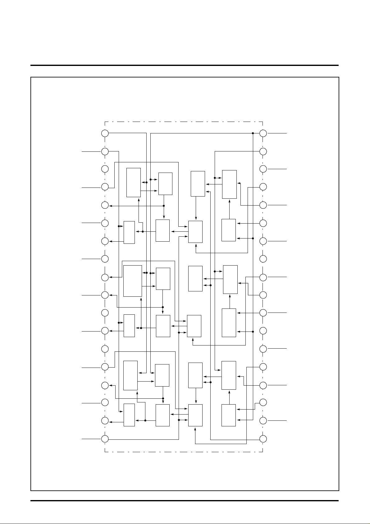
BLOCK DIAGRAM
MITSUBISHI ICs (Monitor)
M52722SP
3-CHANNEL VIDEO PREAMPLIFIER PROVIDED WITH OSD MIX
AND RETRACE LINE BLK FOR HIGH-RESOLUTION
BLK IN
(for retrace)
OSD
(R) SUB
ADJUST
CC2
(R)
V
(G)
GND2
(G)
HOLD
(G)
OUTPUT
BRIGHTNESS
(R)
GND2
(R)
HOLD
(R)
OUTPUT
OSD
(G) SUB
ADJUST
CC2
(G)
V
(B)
GND2
19
20
21
22
23
24
25
26
27
28
29
30
31
G
BRIGHTNESS
BLK
R-ch
G
BRIGHTNESS
BLK
G-ch
R
G
G
R
HOLD
AMP
HOLD
AMP
R OSD
BLANKING
R
OSD MIX
B OSD
BLANKING
G
OSD MIX
R
CONTRAST
R
CLAMP
G
CONTRAST
G
CLAMP
18
17
16
15
14
13
12
11
10
9
8
7
6
MAIN
CONTRAST
(R)
OSD IN
(R)
INPUT
(R)
GND2
(G) SUB
CONTRAST
CC1
(G)
V
CP IN
(R)
GND2
(R) SUB
CONTRAST
CC1
(R)
V
(G)
OSD IN
(G)
INPUT
(B)
GND2
OSD
(B) SUB
ADJUST
CC2
(B)
V
OSD
MAIN
ADJUST
(B)
HOLD
(B)
OUTPUT
32
B
33
34
35
36
BRIGHTNESS
BLK
B-ch
B
B
HOLD
AMP
B OSD
BLANKING
B
OSD MIX
B
CONTRAST
B
CLAMP
5
(B)
OSD IN
4
(B) SUB
IN
(for OSD)
CONTRAST
CC1
(B)
V
3
(B)
INPUT
2
1
BLK
2
Page 3

±
∆
∆
∆
∆
∆
∆
∆
∆
∆
MITSUBISHI ICs (Monitor)
M52722SP
3-CHANNEL VIDEO PREAMPLIFIER PROVIDED WITH OSD MIX
AND RETRACE LINE BLK FOR HIGH-RESOLUTION
ABSOLUTE MAXIMUM RATINGS
(Ta=25˚C)
Symbol Parameter Ratings Unit
V
CC
P
d
T
opr
T
stg’
V
opr
V
opr’
arge
S
ELECTRICAL CHARACTERISTICS
Symbol Parameter
Icc Circuit current
Vomax Output dynamic range
Vimax Maximum allowable input
Gv Maximum gain
Gv Relative maximum gain
V
CR1
CR1
V
CR2
V
V
CR2
V
SCR1
SCR1
V
V
SCR2
V
SCR2
V
SCR3
V
SCR3
Supply voltage 13.0 V
Power dissipation 2403 mW
Operating temperature -20 to +85 ˚C
Storage temperature -40 to +150 ˚C
Recommended operating supply voltage 12.0 V
Recommended operating supply voltage range 11.5 to 12.5 V
Surge pressure
200 V
(Vcc=12V, and Ta=25˚C, unless otherwise noted)
Input External power supply(v) Pulse input Limits
SW3
SW8
SW13
R-ch
G-ch
a_a_a
b
SG5bSG5bSG5
b
SG5bSG5bSG5
b
SG5bSG5bSG5
Take the ratio of the above test values
b
SG5bSG5bSG5
Take the ratio of the above test values
b
SG5bSG5bSG5
Take the ratio of the above test values
b
SG5bSG5bSG5
Take the ratio of the above test values
b
SG5bSG5bSG5
Take the ratio of the above test values
b
SG5bSG5bSG5
Take the ratio of the above test values
V4 V17 V19 V32 V36 SW18
B-ch
55552
_
55
Vari-
5 2.5 2 - -
552--
542--
512--
452--
152--
332--
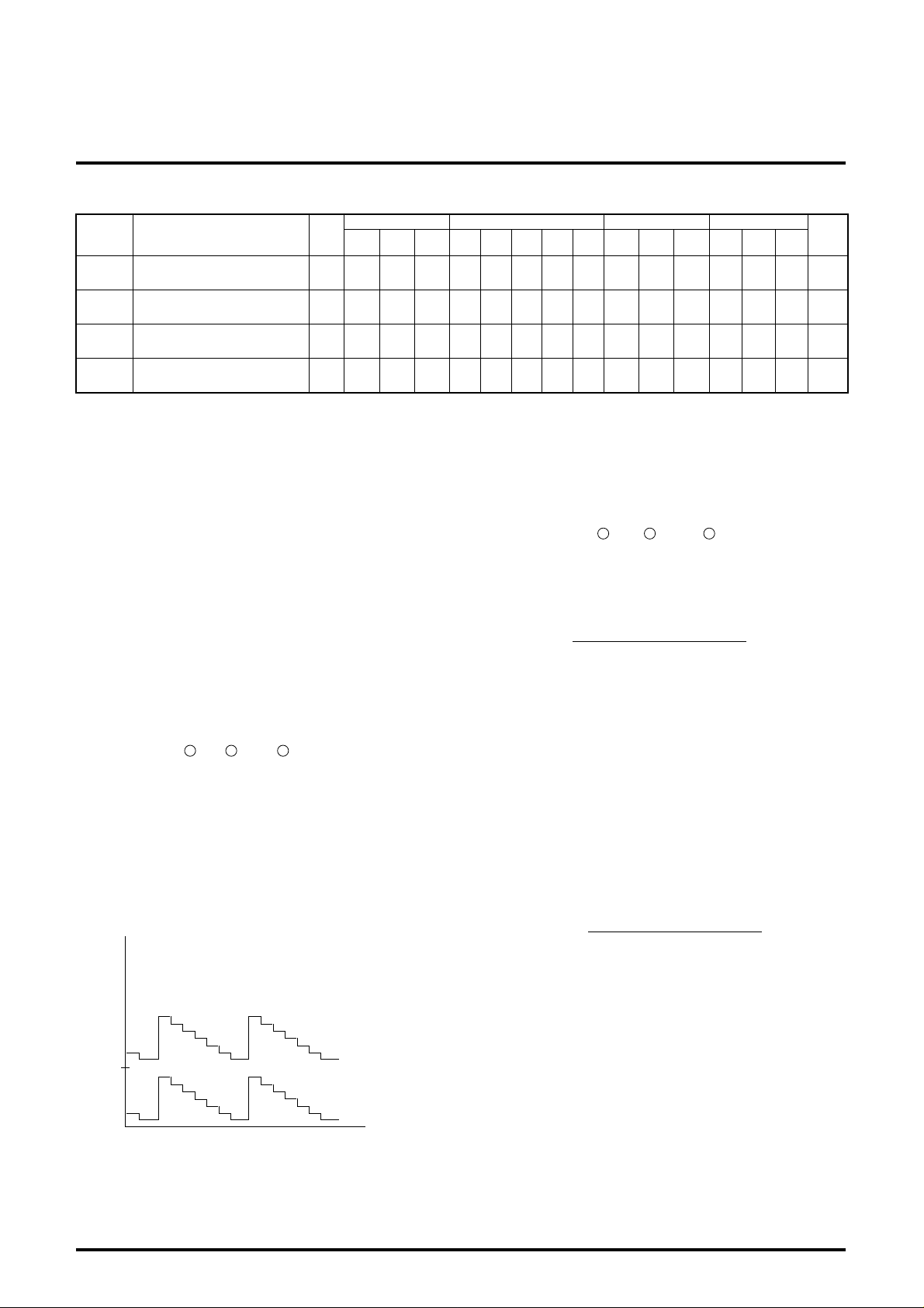
Contrast control characteristics (at typ.)
Relative contrast control
characteristics (at typ.)
Contrast control characteristics (at min.)
Relative contrast control
characteristics (at min.)
Sub-contrast control characteristics (at typ.)
Sub-contrast control characteristics (at typ.)
Sub-contrast control characteristics (at min.)
Relative sub-contrast control
characteristics (at min.)
Contrast and sub-contrast
control characteristics (both
main and sub at typ.)
Relative contrast and subcontrast control characteristics (both main and sub at
Test
point
A
T.P35
T.P30
T.P25
T.P35
T.P30
T.P25
T.P35
T.P30
T.P25
T.P35
T.P30
T.P25
T.P35
T.P30
T.P25
T.P35
T.P30
T.P25
T.P35
T.P30
T.P25
T.P35
T.P30
T.P25
able
typ.)
T.P35
B1
V
V
V
B2
V
V
B3
V
Brightness control characteristics (at max.)
Relative brightness control
B1
characteristics (at max.)
Brightness control character-
istics (at typ.)
Relative brightness control
B2
characteristics (at typ.)
Brightness control character-
istics (at min.)
Relative brightness control
B3
characteristics (at min.)
T.P30
T.P25
T.P35
T.P30
T.P25
T.P35
T.P30
T.P25
a_a_a
Take the ratio of the above test values
a_a_a
Take the ratio of the above test values
a_a_a
Take the ratio of the above test values
554--
_
552--
_
551--
_
--
SW1
SW20
5,10,15
b
SG4a_a_
b
SG4a_a_
b
SG4a_a_
b
SG4a_a_
b
SG4a_a_
b
SG4a_a_
b
SG4a_a_
b
SG4a_a_
b
SG4a_a_
b
SG4a_a_
b
SG4a_a_
b
SG4a_a_
Min. Typ. Max.
Unit
70 100 140 mA
6.0 7.5 9.0 V
1 1.6 - V
15.4 17.4 20 dB
0.8 1 1.2 -
14.3 15.8 17.3 dB
0.8 1 1.2 -
0.4 0.7 1.0 V
0.8 1 1.2 -
14.3 15.8 17.3 dB
0.8 1 1.2 -
0.4 0.8 1.2 V
0.8 1 1.2 -
1.1 1.8 2.5 V
0.8 1 1.2 -
3.0 3.6 4.2 V
-0.3 0 0.3 V
1.1 1.6 2.1 V
-0.3 0 0.3 V
0.3 0.7 1.1 V
-0.3 0 0.3 V
P-P
P-P
P-P
P-P
P-P
3
Page 4

∆
∆
∆
MITSUBISHI ICs (Monitor)
M52722SP
3-CHANNEL VIDEO PREAMPLIFIER PROVIDED WITH OSD MIX
AND RETRACE LINE BLK FOR HIGH-RESOLUTION
∆
∆
ELECTRICAL CHARACTERISTICS
Symbol Parameter
C1
F
F
F
C1
F
F
C2
F
Frequency characteristics
(f=50MHz at max.)
Relative frequency character-
C1
istics (f=50MHz at max.)
Frequency characteristics
’
(f=180MHz at max.)
Relative frequency character-
’
C1
istics (f=180MHz at max.)
Frequency characteristics
(f=180MHz at typ.)
Relative frequency character-
C2
istics (f=180MHz at typ.)
C.T.1 Crosstalk1(f=50MHz)
C.T.1’ Crosstalk1(f=180MHz)
C.T.2 Crosstalk2(f=50MHz)
C.T.2’ Crosstalk2(f=180MHz)
C.T.3 Crosstalk3(f=50MHz)
C.T.3’ Crosstalk3(f=180MHz)
Tr Pulse characteristics 1
Tf Pulse characteristics 2
V14th
W14
DCH
P
P
DCL
Clamping pulse threshold
voltage
Clamping pulse operation
min. width
Pedestal voltage temper ature
characteristics1
Pedestal voltage temper ature
characteristics2
OTr OSD pulse characteristics 1
OTf OSD pulse characteristics 2
Oaj1
Main OSD adjustment control
characteristics (at max.)
Relative main OSD adjust-
Oaj1
ment control characteristics
(at max.)
Oaj2
Main OSD adjustment control
characteristics (at min.)
Relative main OSD adjust-
Oaj2
ment control characteristics
(at min.)
OSDth OSD input threshold voltage
V1th BLK input threshold voltage
Test
point
T.P35
T.P30
T.P25
T.P35
T.P30
T.P25
T.P35
T.P30
T.P25
T.P35
T.P30
T.P25
T.P35
T.P30
T.P25
T.P35
T.P30
T.P25
T.P35
T.P30
T.P25
T.P35
T.P30
T.P25
T.P35
T.P30
T.P25
T.P35
T.P30
T.P25
T.P35
T.P30
T.P25
T.P35
T.P30
T.P25
T.P35
T.P30
T.P25
T .P35
T .P30
T .P25
T .P35
T .P30
T .P25
T.P35
T.P30
T.P25
T.P35
T.P30
T.P25
T.P35
T.P30
T.P25
T.P35
T.P30
T.P25
T.P35
T.P30
T.P25
T.P35
T.P30
T.P25
(cont.)
Input External power supply(v) Pulse input Limits
SW3
SW8
R-ch
G-ch
b
SG1bSG1bSG1
b
SG2bSG2bSG2
b
SG2bSG2bSG2
b
SG1a_a_
b
SG2a_a_
a_b
SG1a_
a_b
SG2a_
a_a_b
a_a_b
b
SG3bSG3bSG3
b
SG3bSG5bSG5
b
SG5bSG5bSG5
b
SG5bSG5bSG5
b
SG5bSG5bSG5
b
SG5bSG5bSG5
a_a_a
a_a_a
a_a_a
a_a_a
a_a_a
b
SG5bSG5bSG5
SW13
V4 V17 V19 V32 V36 SW18
B-ch
Vari-
5
Take the ratio of the above test values
5
Take the ratio of the above test values
5
Take the ratio of the above test values
able
Vari-
able
Vari-
able
---
---
---
55---
55---
55---
55---
55---
SG1
55---
SG2
Vari-
able
Vari-
able
Vari-
able
Vari-
able
--
--
5
5
552--
552--
552--
552--
55
_
55
_
55254
_
Take the ratio of the above test values
55250
_
Take the ratio of the above test values
55255
_
Vari-
able
Vari-
able
Vari-
5
able
Vari-
5
able
55255
SW1
SW20
5,10,15
c
a
_
_
c
a
_
_
c
a
_
_
c
a
_
_
c
a
_
_
c
a
_
_
c
a
_
_
c
a
_
_
c
a
_
_
b
SG4a_a_
b
SG4a_a_
b
SG4a_a_
b
SG4a_a_
b
SG4a_a_
b
SG4a_a_
SW1 is
b
a, and
others b.
SG4
SG6
SW1 is
b
a, and
others b.
SG4
SG6
b
SG4b SG6a_
b
SG4bSG6a_
SW1 is
b
a, and
others b.
SG4
SG6
SW1 is
a, and
b
others b.
SG4
SG6
Min. Typ. Max.
a
-2 0 2.5 dB
_
-1 0 1 -
a
-3 -2.3 3 dB
_
-1 0 1 -
a
-3 0 3 dB
_
-1 0 1 -
a
- -30 -20 dB
_
a
- -20 -15 dB
_
a
- -30 -20 dB
_
a
- -20 -15 dB
_
a
- -30 -20 dB
_
a
- -20 -15 dB
_
- 2 - nsec
- 2 - nsec
1.0 1.5 2.5 V
0.2 0.5 - µ sec
-0.3 0 0.3 V
-0.3 0 0.3 V
a
- 3 6 nsec
_
a
- 3 6 nsec
_
3.7 4.3 5.0 V
0.8 1 1.2 -
- 0 0.5 V
0.8 1 1.2 -
a
1.7 2.5 3.5 V
_
a
1.7 2.5 3.5 V
_
Unit
DC
DC
DC
P-P
P-P
DC
DC
4
Page 5
ELECTRICAL CHARACTERISTICS (cont.)
8
VCR1=20LOG
V
OR2(VOG2, VOB2) [VP-P]
0.7 [VP-P]
∆VCR1=VOR1/VOG1, VOG1/VOB1, VOB1/VOR1
Symbol Parameter
SOaj1
SOaj2
HBLK
HVth
SUB OSD adjustment control
characteristics (at typ.)
SUB OSD adjustment control
characteristics (at min.)
Retrace line BLK characteristics
Retrace line BLK input
threshold value
Test
point
T.P35
T.P30
T.P25
T.P35
T.P30
T.P25
T.P35
T.P30
T.P25
T.P35
T.P30
T.P25
SW3
R-ch
MITSUBISHI ICs (Monitor)
M52722SP
3-CHANNEL VIDEO PREAMPLIFIER PROVIDED WITH OSD MIX
AND RETRACE LINE BLK FOR HIGH-RESOLUTION
Input External power supply(v) Pulse input Limits
SW8
SW13
G-ch
B-ch
a_a_a
a_a_a
a_a_a
a_a_a
V4 V17 V19 V32 V36 SW18
55225
_
55205
_
55200
_
55200
_
SW1
SW20
5,10,15
b
SG4bSG6a_
b
SG4bSG6a_
a_a_b
SG7
a_a_b
SG7
Min. Typ. Max.
1.6 2.2 2.6 V
- 0 0.5 V
- 0.2 0.5 V
0.5 1.5 2.5 V
Unit
P-P
P-P
DC
DC
ELECTRICAL CHARACTERISTICS TEST METHOD
Note: SW/NO of signal input pin and SW/NO of pulse input pin,
which have already been described in the electrical characteristics
table, are omitted, and SW/NO of external power supply will only be
described as follows:
Sub-OSD adjustment voltages, V32, V27 and V22, which are
always set to the identical value, are represented by V32 in the
electrical characteristics table. In addition, sub-contrast voltages,
V4, V9 and V14, which are also set to the identical value, are
represented by V4 in the electrical characteristics table.
Icc circuit current
Conditions shall be as specified in the electrical characteristics
table, and take measurements with ammeter A when SW A is turned
to the b side.
Vomax output dynamic range
Follow the following procedure to set V19.
13
1. Input SG5 to pin (pin or pin ), gradually reduce V19, and
read the lower part voltage when the lower part of input
waveform of T.P25 (T.P30 or T.P35) is distorted to let the reading
OLR (VOLG or VOLB).
be V
2. Then, gradually raise V19, and read the upper part voltage when
the upper part of output waveform of T.P25 (T.P30 or T.P35) is
distorted to let the reading be V
3. Vomax is found by:
Vomax=VOHR(VOHG, VOHB)-V OLR(V OLG, VOLB)
8 3
OHR (VOHG or VOHB).
Vimax maximum allowable input
Change V17 to 2.5V, gradually increase input signal amplitude from
700m V
P-P, and read input signal amplitude when output signal
starts to be distorted.
Gv and ∆Gv maximum gain and relative maximum gain
1. Input SG5 to pin (pin or pin ), and read the output
13
3
amplitude of T.P25 (T.P30 or T.P35) at this time to let the reading
OR1 (VOG1 or VOB1).
be V
2. Maximum gain Gv is found by:
V
GV=20LOG
OR1(VOG1, VOB1) [VP-P]
0.7 [VP-P]
3. Relative maximum gain ∆G is found by
V=VOR1/VOG1, V OG1/VOB1, V OB1/VOR1
∆G
through respective calculation.
CR1 contrast control characteristics and
V
∆V
CR1 relative contrast control characteristics (at typ.)
1. Follow the electrical characteristics table except changing V17 to
4V.
2. Read the output amplitude of T.P25 (T.P30 or T.P35) at this time,
and let the reading be VOR2 (VOG2 or VOB2).
3. Contrast control characteristics VCR1 and relative contrast
control characteristics ∆VCR1 is found by
(V)
5.0
0.0
T.P25 output waveform (T.P30 and T.P35 are also the same)
5
through respective calculation.
CR2 contrast control characteristics and
V
∆V
CR2 relative contrast control characteristics (at min.)
1. Follow the electrical characteristics table except changing V17 to
1.0V.
2. Read the output amplitude of T.P25 (T.P30 or T.P35) at this time
to let the reading be VOR3 (VOG3 or VOB3). This value represents
VCR2.
3. Relative contrast control characteristics ∆VCR2 is found by:
VOR2 = VOR3/ VOG3,V OG3/ V OB3/ ,VOB3/VOR3
Page 6

MITSUBISHI ICs (Monitor)
∆VB3=VOR7’’ VOG7’’ [V]
=V
OG7’’ VOB7’’
=VOB7’’ VOR7’’
8
M52722SP
3-CHANNEL VIDEO PREAMPLIFIER PROVIDED WITH OSD MIX
AND RETRACE LINE BLK FOR HIGH-RESOLUTION
VSCR1 sub-contrast control characteristics and
∆
VSCR1 relative sub-contrast control characteristics (at typ.)
1. Follow the electrical characteristics table except changing V4,V9
and V14 to 4.0V.
2. Read the output amplitude of T.P25 (T.P30 or T.P35) to let the
reading be VOR4 (VOG4 or VOB4).
3. Sub-contrast control characteristics VSCR1 and relative subcontrast control characteristics ∆VSCR1 are found by
V
SCR1=20LOG
V
OR4(VOG4, VOB4) [VP-P]
0.7 [VP-P]
∆VSCR1=VOR4/VOG4, VOG4/V OB4, V OB4/VOR4
through respective calculation.
SCR2 sub-contrast control characteristics and
V
∆V
SCR2 relative sub-contrast control characteristics (at min.)
1. Follow the electrical characteristics table except changing V4, V9
and V14 to 1.0V.
2. Read the output amplitude of T.P25 (T.P30 or T.P35) at this time
to let the reading be VOR5 (VOG5 or VOB5). This value represents
VSCR2.
3. Relative sub-contrast control characteristics ∆VSCR2 is found by:
∆VSCR2=VOR5/VOG5, VOG5/V OB5, V OB5/VOR5
VSCR3 contrast and sub-contrast control characteristics and
∆V
SCR3 relative contrast and sub-contrast control
characteristics (at typ.)
1. Follow the electrical characteristics table except changing V17 to
3.0V, and V4, V9 and V14 to 3.0V.
2. Read the output amplitude of T.P25 (T.P30 or T.P35) at this time,
and let the reading be VOR6 (VOG6 or VOB6). This value
represents VSCR3.
3. Relative sub-contrast control characteristics ∆VSCR3 is found by:
∆VSCR3 =VOR6/VOG6, VOG6/V OB6, V OB6/VOR6
VB1 brightness control characteristics and
∆V
B1 relative brightness characteristics (at max.)
1. The conditions shall be as specified in the electrical
characteristics table.
2. Measure the output of T.P25 (T.P30 or T.P35) at this time with an
ammeter, and let it be VOR7 (VOG7 or VOB7) to let it be VB1,
respectively.
3. For relative control characteristics, further, measure difference
between channels from VOR7, V OG7 or VOB7.
3. For relative brightness control characteristics ∆V
B2, further,
calculate difference between channels from VOR7, VOG7 or VOB7.
∆VB2=VOR7’ VOG7’ [V]
=V
OG7’ VOB7’
=VOB7’ VOR7’
B3 brightness control characteristics and
V
∆V
B3 relative brightness control characteristics (at min.):
1. The conditions shall be as specified in the electrical
characteristics table.
2. Use an ammeter to measure the output of T.P25 (T.P30 or T.P35)
at this time to let the value be VOR7" (VOG7" or VOB7"). This value
represents VB3.
3. For relative control characteristics ∆VB3, further, calculate
difference between channels from VOR7", VOG7" or VOB7".
FC1 and ∆FC1 frequency characteristics 1 and relative
frequency characteristics (f=50MHz at max.) and
F
C1' and ∆FC1' frequency characteristics 1 and relative
frequency characteristics (f=180MHz at max.)
1. The conditions shall be as specified in the electrical charactristics
table.
2. Whilst SG1 and SG2 are used, input SGA first, apply voltage to
the input pin (pin , pin or pin ) through about 2k Ω of
3
13
resistor so as to provide 2.5V on the lower side of input signal. In
addition, apply voltage to the hold pin (pin , pin or pin ) to
23 28 33
ensure that the output wave of T.P25 (T.P30 or T.P35) will not be
jammed so as to allow the lower side of the sine wave, an output
signal to be 2V. Adjust the main contrast voltage (17V) at this
time to allow the output amplitude to be 4.0V
P-P. Then, change
the input signal to SG1 or SG2 to measure each output
amplitude.
3. Now, when letting this test value be
output amplitude 4.0VP-P when SGA is input,
output amplitude VOR 8 (VOG8 or VOB8)
when SG1 is input, and
output amplitude VOR9 (VOG9 or VOB9),
frequency characteristics FC1 or FC1' is calculated from:
∆VB1=VOR7 VOG7 [V]
=V
OG7 VOB7
=VOB7 VOR7
V
B2 brightness control characteristics and
∆V
B2 relative brightness control characteristics (at typ.)
1. The conditions shall be as specified in the electrical
characteristics table.
2. Use an ammeter to measure the output of T.P25 (T.P30 or T.P35)
at this time to let the value be VOR7 (VOG7 or VOB7). This value
represents VB2.
V
FC1=20LOG
FC1’=20LOG
OR8(VOG8, VOB8) [VP-P]
4.0 [VP-P]
V
OR9(VOG9, VOB9) [VP-P]
4.0 [VP-P]
4. F or relativ e frequency bands ∆F
in FC1 and FC1 for each channel.
C1 and ∆FC1', calculate difference
6
Page 7

MITSUBISHI ICs (Monitor)
OTr (nsec) = (OTr2)2 - (OTr1)
2
OTf (nsec) = (OTf2)2 - (OTf1)
2
M52722SP
3-CHANNEL VIDEO PREAMPLIFIER PROVIDED WITH OSD MIX
AND RETRACE LINE BLK FOR HIGH-RESOLUTION
FC2 and ∆FC2 frequency characteristics 2 and relative
frequency characteristics 2 (f=180MHz at typ.)
The same as for F
C1, ∆FC1 and ∆FC1' applies except adjusting the
main contrast voltage (V17) and allowing the amplitude of output
signal when SGA is input to be 1.0V
P-P.
C.T.1 crosstalk 1 (f=50MHz) and
C.T.1' crosstalk 1 (f=180MHz)
1. The conditions shall be as specified in the electrical
characteristics. (Set the input pin and hold pin as in the case of
C1, ∆FC1, FC1' and ∆FC1')
F
2. Input SG1 (or SG2) to pin (R-ch) only, measure the output
waveform amplitude of T.P25 (T.P30 or T.P35) to be V
13
OR, VOG or
VOB.
3. Crosstalk C.T.1 (C.T.1')
C.T.1=20log
(C.T.1’)
VOG or VOB [VP-P]
VOR [VP-P]
[dB]
C.T.2 crosstalk 2 (f=50MHz) and
C.T.2' corsstalk 2 (f=180MHz)
1. Change the input pin to pin (G-ch), and read the output as in
8
the case of C.T.1 or C.T.1'.
2. Crosstalk C.T.2 (C.T.2') is found by:
C.T.2=20log
(C.T.2’)
VOR or VOB [VP-P]
VOG [VP-P]
[dB]
C.T.3 crosstalk 3(f=50MHz) and
C.T.3' crosstalk 3(f=180MHz)
1. Change the input pin to pin (B-ch), and read the output as in
3
the case of C.T.1 or C.T.1'.
2. Crosstalk C.T.3 (C.T.3') is found by:
C.T.3=20log
(C.T.2’)
VOR or VOG [VP-P]
VOB [VP-P]
[dB]
Tr, and Tf, Pulse characteristics 1 and pulse characteristics 2
1. The conditions shall be as specified in the electrical
characteristics table. Adjust the main contrast voltage (V17) and
brightness voltage (V19), and allow the output signal amplitude
to be 4.0Vp-p, and the black level 2.0V.
2. Use an active probe to measure rise Tr1 and fall Tf1 at 10% to
90% of input pulse.
3. Then, use an active probe to measure rise Tr2 and fall Tf2 at 10%
to 90% of output pulse.
4. Pulse characteristics Tr and Tf:
Tr (nsec) = (Tr2)2 - (Tr1)
Tf (nsec) = (Tf2)2 - (Tf1)
100%
0%
Tr1
Tr2
2
2
90%
10%
or
Tf1
Tf2
or
V14th clamping pulse threshold voltage
1. The conditions shall be as specified in the electrical characteristic
table.
2. Gradually reduce SG4 level at this time, while monitoring the
output signal (pedestal voltage: about 1.8V), and measure SG4
top level when the pedestal voltage of output signal is not
stabilized and starts to fall.
W14 minimum clamping pulse operation width
Gradually reduce SG4 pulse width, and measure SG4 pulse width
(1.5V from GND) when the pedestal voltage of output signal is not
stabilized and starts to fall.
DCH and PDCL, pedestal voltage temperature characteristics 1
P
and pedestal voltage temperature characteristics 2
1. The conditions shall be as specified in the electrical
characteristics table.
2. Measure pedestal v oltage at room temperature to let the v alue be
P
DC1.
3. Then, measure pedestal voltage at -20˚C and 85˚C to let the
value be PDC2 or PDC3.
4. PDCH=PDC1-PDC2
PDCL=PDC1-PDC3
OTr and OTf, OSD pulse characteristics 1 and OSD pulse
characteristics 2
1. The conditions shall be as specified in the electrical
characteristics table. Adjust main OSD adjustment voltage (V36)
and brightness voltage (V19) to allow output signal amplitude to
become 3.0Vp-p, and black level 2.0.
2. Use an activ e probe to measure rise O Tr1 and fall OTf1 at 10% to
90% of input pulse.
3. Use an active probe to measure rise OTtr2 and fall OTf2 at 10%
to 90% of output pulse.
4. OSD pulse characteristics OTr and OTf are found by:
7
Page 8

MITSUBISHI ICs (Monitor)
M52722SP
3-CHANNEL VIDEO PREAMPLIFIER PROVIDED WITH OSD MIX
AND RETRACE LINE BLK FOR HIGH-RESOLUTION
Oaj1 main OSD adjustment control characteristics (at max.)
and
∆Oaj1 relative main OSD adjustment control characteristics (at
max.)
1. The conditions shall be as specified in the electrical
characteristics table.
2. Let output signal pedestal voltage of T.P25 (T.P30 or T.P35) be
V
LRA (VLGA or VLBA) and voltage in the OSD area be VHRA (VHGA
or VHBA).
3. If letting Oaj1 be VORA (VOGA or VOBA),
Oaj1=VORA (VOGA, VOBA) = VHRA-VLRA
(VHGA-VLGA, VHBA-VLBA)
4. Relative OSD adjustment control characteristics ∆Oaj1:
∆Oaj1=VORA/VOGA, VOGA/V OBA, V OBA/VORA
Oaj2 main OSD adjustment control characteristics (at min.)
and
∆Oaj2 relative main OSD adjustment control characteristics (at
min.)
Change V36 to 0V, and obtain Oaj2 or ∆Oaj2 as in the case of Oaj1
or ∆Oaj1.
OSDth OSD input threshold voltage
1. The conditions shall be as specified in the electrical
characteristics table.
2. Gradually reduce SG6 level at this time, while monitoring the
output, and measure top SG6 level when output is stopped to let
the value be OSDth.
V1th BLK input threshold voltage
1. The conditions shall be as specified in the electrical
characteristics table.
2. Verify at this time that no signal is output with a timing in which
output is synchronized with SG6.
(OSD blanking period)
3. Gradually reduce SG6 level at this time, while monitoring the
output, and measure top SG level when OSD blanking period
expires to let the value be V1th.
SOaj1 SUB OSD adjustment control characteristics (at typ.)
and
SOaj2 SUB OSD adjustment control characteristics (at min.)
1. The conditions shall be as specified in the electrical
characteristics table.
2. Read output amplitude of T.P25 (T.P30 or T.P35) at this time, and
let the reading be V
Soaj2.
HBLK retrace line BLK characteristics
1. The conditions shall be as specified in the electrical
characteristics table.
2. Monitor output at this time, and read trace line blanking level to
let the reading be H
HVth retrace line BLK input threshold voltage
1. The conditions shall be as specified in the electrical
characteristics table.
2. Verify that blanking is performed with a timing in which output is
synchronized with SG7. Gradually reduce SG7 level, while
ORC (VOGC or VOBC) to let it be Soaj1 or
BLK.
monitoring the output, and measure top SG7 level when blanking
period expires to let the reading be HVth.
8
Page 9

INPUT SIGNAL
SG No. Signals
3-CHANNEL VIDEO PREAMPLIFIER PROVIDED WITH OSD MIX
Sine wave with an amplitude of 0.7V
MITSUBISHI ICs (Monitor)
M52722SP
AND RETRACE LINE BLK FOR HIGH-RESOLUTION
P-P
SGA
SG1 Sine wave with an amplitude of 0.7VP-P (f = 50MHZ)
SG2 Sine wave with an amplitude of 0.7VP-P (f = 180MHZ)
Video signal with an amplitude of 0.7VP-P (f = 1MHZ,duty = 50%)
Lo section shall be synchronized with SG4 pulse.
SG3
Pulse with an amplitude of 2.5V
able) synchronized with the pedestal section of standard video stage wave
P-P and a pulse width of 0.5µs (Pulse width, amplitude and frequency are vari-
SG4
OV
Video signal with an amplitude of
0.7VP-P (f=30kHz, amplitude is
partially variable.)
Video stage wave
2.5V
P-P
0.5µs 0.5µs
0.7VP-P
0.7VP-P
BLK (for OSD)
OSD signal
Retrace line
BKL signal
Pulse with an amplitude of 4.0VP-P
and a pulse width of 15µs
synchronized with the image
section of standard video stage
wave. (Amplitude is partially
variable.)
Pulse with an amplitude of 4.0V
P-P
and a pulse width of 15µs
synchronized with the image
section of standard video stage
wave. (Amplitude is partially
variable.)
4V
0V
4V
0V
9
Page 10

TEST CIRCUIT
MITSUBISHI ICs (Monitor)
M52722SP
3-CHANNEL VIDEO PREAMPLIFIER PROVIDED WITH OSD MIX
AND RETRACE LINE BLK FOR HIGH-RESOLUTION
SG7
V22
V19
c
SW18
b
b
a
SW20
0.01µ
330 2.2µ
V27
2.2µ
330
M52722SP
47µ
8 9 10 1211 13 1814 1715 16
47µ
7
a
V17
b
SW15
a
V14
SW13
SW10
b
a
V9
0.01µ
SW8
SG4
a
b
a
b
V36
2.2µ
330
V32
6
b
SW5
a
0.01µ
47µ
SW1
V4
a
b
SW3
b
a
SG6
100µ
0.01µ
A
45
CC GND VCC GND VCC GND
V
CC GND VCC GND VCC GND
V
36 35 34 33 32 31 30 29 28 27 2526 24 1923 2022 21
123
SG6
SGA
SG1
SG2
SG3
b
SWA
a
Units Resistance : Ω
Capacitance : F
12V
SG5
10
Page 11

TYPICAL CHARACTERISTICS
THERMAL DERATING (MAXIMUM RATING)
2400
2016
2000
1600
1200
800
400
POWER DISSIPATION Pd (mW)
0
-20 0 75 150
OPERATING TEMPERATURE Ta (˚C)
50
25
MITSUBISHI ICs (Monitor)
M52722SP
3-CHANNEL VIDEO PREAMPLIFIER PROVIDED WITH OSD MIX
AND RETRACE LINE BLK FOR HIGH-RESOLUTION
When mounted with
standard substrate
125
100
85
11
Page 12
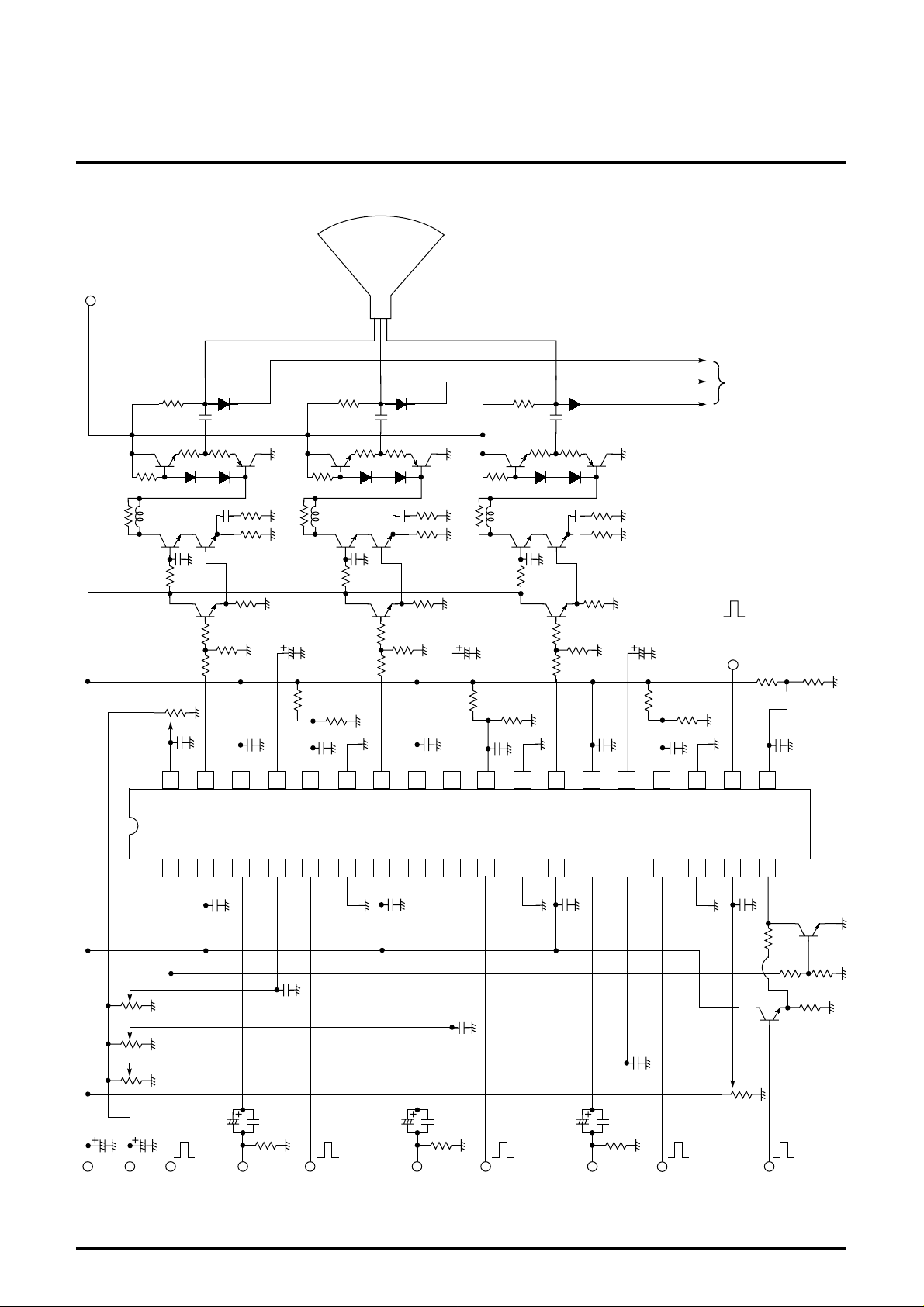
APPLICATION EXAMPLE
110V
MITSUBISHI ICs (Monitor)
M52722SP
3-CHANNEL VIDEO PREAMPLIFIER PROVIDED WITH OSD MIX
AND RETRACE LINE BLK FOR HIGH-RESOLUTION
CRT
DC CLAMP
2.2µ
0~5V
0.1µ
36 35 33 3234 31 30 28 2729 26 25 23 2224 21 20 19
0.01µ 0.1µ 0.01µ 0.1µ 0.01µ 0.1µ 0.1µ
2.2µ 2.2µ
6V6V 6V
330330330
M52722SP
12 4536791081112141513 16 17 18
0.01µ
0 to 5V
0 to 5V
0 to 5V
0.1µ
0.1µ
0.1µ
BLK IN
(for retrace)
0.1µ0.01µ0.01µ
0 to 5V
≈
2.2V
12V CLAMP BLK IN
5V
(for OSD)
47µ
0.01µ
75 75 75
INPUT
(B)
OSD IN
(B)
47µ
INPUT
(G)
0.01µ
OSD IN
(G)
47µ
INPUT
(R)
0.01µ
OSD IN
(R)
Units Resistance : Ω
Capacitance : F
12
Page 13

3-CHANNEL VIDEO PREAMPLIFIER PROVIDED WITH OSD MIX
AND RETRACE LINE BLK FOR HIGH-RESOLUTION
DESCRIPTION OF PIN
Pin No. Name Peripheral circuit of pins
B-ch
G-ch
1
BLK IN(for OSD) -
2
VCC (B)
7
VCC (G)
1
0.9mA
2.5V
Vcc
GND
MITSUBISHI ICs (Monitor)
M52722SP
DC
voltage
12
Description of function
• EInput pulse between 3.5V and 5V.
• Ground to GND when not in use.
• Apply identical voltage to all 3 chan-
nels.
3.5V to 5V
less than 1V
VCC (R)
12
3
INPUT (B)
8
INPUT (G)
INPUT (R)
13
4
SUB CONTRAST (B)
9
SUB CONTRAST(G)
SUB CONTRAST (R)
14
2kΩ
0.24mA
1.5kΩ
23.5kΩ
CP
2kΩ
2.5V
2.5V
Vcc
GND
Vcc
GND
• Clamped to about 2.5V by clamping
pulse at pin 18.
Input at a low impedance.
2.5
• Use at less than 5V to ensure stable
operation.
2.5
13
5
10
15
OSD IN (B)
OSD IN (G)
OSD IN (R)
1.1mA
2.5V
Vcc
GND
• Input pulse between 3.5V and 5V.
3.5V to 5V
1V or less
-
• Ground to GND when not in use.
Page 14

3-CHANNEL VIDEO PREAMPLIFIER PROVIDED WITH OSD MIX
AND RETRACE LINE BLK FOR HIGH-RESOLUTION
DESCRIPTION OF PIN (cont.)
Pin No. Name Peripheral circuit of pins
31
6
GND (B)
11 26
GND (G)
GND (R)
16 21
11kΩ
Vcc
MITSUBISHI ICs (Monitor)
M52722SP
DC
voltage
GND
Description of function
• Use at less than 5V to ensure stable
operation.
17
MAIN CONTRAST 2.5
18
CP IN -
19
MAIN BRIGHTNESS -
18
19
41kΩ
17
B-ch
G-ch
2.5V
GND
Vcc
41kΩ
2.2V
GND
Vcc
20.3kΩ
• Input more than 2.5V of pulse.
more than 2.5V
less than 1V
• IInput at a low impedance.
GND
Vcc
B-ch
G-ch
20
BLK IN (for retrace) -
20
45kΩ
2.1V
GND
0.25mA
• IInput pulse between 2.5V and 5V.
2.5 to 5V
less than 0.5V
• Ground to GND when not in use.
14
Page 15

3-CHANNEL VIDEO PREAMPLIFIER PROVIDED WITH OSD MIX
AND RETRACE LINE BLK FOR HIGH-RESOLUTION
DESCRIPTION OF PIN (cont.)
Pin No. Name Peripheral circuit of pins
50kΩ65kΩ 65kΩ
22
SUB OSD ADJUST (R)
27
SUB OSD ADJUST (G)
SUB OSD ADJUST (B)
32
1k
MITSUBISHI ICs (Monitor)
M52722SP
DC
voltage
V
CC
When
open
5.5V
55kΩ55kΩ
GND
Description of function
• Open or pull up to Vcc when not in
use.
23
28
33
24
29
34
25
30
35
HOLD (R)
HOLD (G)
HOLD (B)
VCC2 (R)
VCC2 (G)
VCC2 (B)
OUTPUT (R)
OUTPUT (G)
OUTPUT (B)
0.2mA
Pin
Pin
Pin
1kΩ
50Ω
VCC
• Capacitance is required between
GNDs.
Vari-
able.
GND
• A power supply dedicated to output
emitter follower. Apply identical voltage to all 3 channels.
24
29
34
12
Apply
• Resistor is required on the GND
side. Set arbitrarily to provide less
than 15mA by drive capability
Pin
Pin
Pin
25
30
35
Vari-
able
required.
15
36
MAIN OSD ADJUST
1kΩ
55kΩ
10P
50kΩ65kΩ 65kΩ
55kΩ
V
CC
GND
• Open or pull up to Vcc when not in
use.
Apply
5.5V
Page 16

MITSUBISHI ICs (Monitor)
0
1
2
3
4
5
6
1
2
3
4
5
Output DC voltage (V)
Brightness voltage (V)
M52722SP
3-CHANNEL VIDEO PREAMPLIFIER PROVIDED WITH OSD MIX
AND RETRACE LINE BLK FOR HIGH-RESOLUTION
M52722SP - INSTRUCTIONS FOR USE
1) Clamping pulse input
Input positive polarity pulse.
Clamping pulse threshold voltage VTH is calculated by the
following equation, and voltages more than 2.2 V is subject
toLIM:
VTH = 2.2 V- Diode
= 1.5V
Recommended clamping pulse voltage is as given in the
following
diagram:
In addition, pulse width is recommended as follows:
More than 1.0µ sec at 15kHz,
More than 0.5µ sec at 30kHz, and
More than 0.3µ sec at 64kHz.
X1
2.5V to 5.0V
VTH(1.5V)
0V
2) Brightness operation
(1 to 5V)
DC level shift
+
19
-
Signal
+
Brightness
The above diagram represents its principle.
2-1) Brightness pins
Use within the range of 1V to 5V.
Control characteristics are as given in the following drawing:
Clamping pulse wiring generally involves long stretched lines in
the set, is made from the high pressure side, and often
connected indirectly to external pins, causing strong surge input
to tend to come into. Under such circumstances, protective
circuit as given in the following diagram is recommended:
18
2-2) Sub-brightness
This IC has no sub-brightness function.
2-3) Capacitance value of holding capacitor
Value necessary as IC is more than 0.01É (when fH=15kHz).
However, this depends upon hold period (time other than for
clamping), and the longer the hold time is, the greater the
value is necessary.
In terms of application, the smaller the capacitance value, the
quicker the response, and the greater the capacitance value,
the more stable the behavior.
Accordingly, set freely depending upon signals and clamping
pulse contents (especially pulse status in a vertically
synchronized timing).
3) BLK (for OSD) and OSD input pins
• Input formula is on an open basis.
(See page 2-1109.)Threshold voltage is 2.5V.
• Inputting OSD mix signal without inputting BLK pulse will cause
abnormal operation. Input BLK pulse as well whenever inputting
OSD Mix signal.
• Ensure that input pin is grounded when OSD Mix function is not
used.
16
Page 17

3-CHANNEL VIDEO PREAMPLIFIER PROVIDED WITH OSD MIX
• OSD display period overlapped with clamping pulse period will
cause abnormal operation. As measures against this, external
circuit as given in the following diagram is recommended:
Vcc
C/P
18
BLK
(for OSD)
1
4) Retrace line BLK input pins
• Input formula is open.
(See page 2-1110.)
• Threshold voltage is 1.5V.
• Ensure that input pin is grounded when no retrace line BLK func-
tion is used.
MITSUBISHI ICs (Monitor)
M52722SP
AND RETRACE LINE BLK FOR HIGH-RESOLUTION
5) Main, Sub OSD adjustment pins
• Use within the range of 0V-5V.
• Control characteristics are as given in the following drawing:
• Open if main OSD adjustment or sub OSD adjustment is not
used.
• If, in application, wiring on the substrate causes interference
wave to get into these pins, affecting even IC input, consider
addition of such as bus controller.
• Ensure that main, sub OSD adjustment pins are open or
grounded when no OSD Mix function is used.
Sub OSD adjust 5V
(Main OSD adjust 5V)
Sub OSD adjust 4V
(Main OSD adjust 4V)
Sub OSD adjust 3V
(Main OSD adjust 3V)
Sub OSD adjust 2V
Output amplitude
0
PRECAUTIONS FOR APPLICATION
2
1
Main OSD adjust (V)
(Sub OSD adjust)
4
3
(Main OSD adjust 2V)
Sub OSD adjust 1V
(Main OSD adjust 1V)
6
5
• Wire output pins to output pulldown resistors at a shortest dis-
tance.
• Voltage in the IC output signal pedestal area is recommended f or
use at about 2V.
17
 Loading...