

Page 1
MITSUBISHI <CONTROL / DRIVER IC>
)
(+)
y
M51970L
MOTOR SPEED CONTROL
DESCRIPTION
The M51970L is a semiconductor integrated circuit designed to
control the motor rotating speed.
Connection of the rotating speed detector (F-G detector) to the
input keeps the motor rotating speed constant with high precision.
Connection of an appropriate power transistor to the output
controls a wide range of DC motors.
FEATURES
●Wide range of supply voltage •••••••••••••2.5 – 18V (-20 – +75˚C)
●Variation coefficient of supply voltage
• • • • • • • • • • • ±0.1% standard (4 – 15V)
●Load variation coefficient ••••••••••••••••••••••••••±0.1% standard
●Temperature coefficient of rotating speed
• • • • • • • • • • • • • • ±10 ppm/˚C (standard)
(-20 – +75˚C)
● The built-in over-shoot prevention circuit keeps the over-shoot
low.
● DC drive system with minimum RFI
APPLICATION
Motor rotating control in the player, tape recorder, etc.
RECOMMENDED OPERATING CONDITIONS
Supply voltage range ••••••••••••••••••••••••••••••••••••••••2.5–18V
Rated supply voltage ••••••••••••••••••••••••••••••••••••••••••••••• 9V
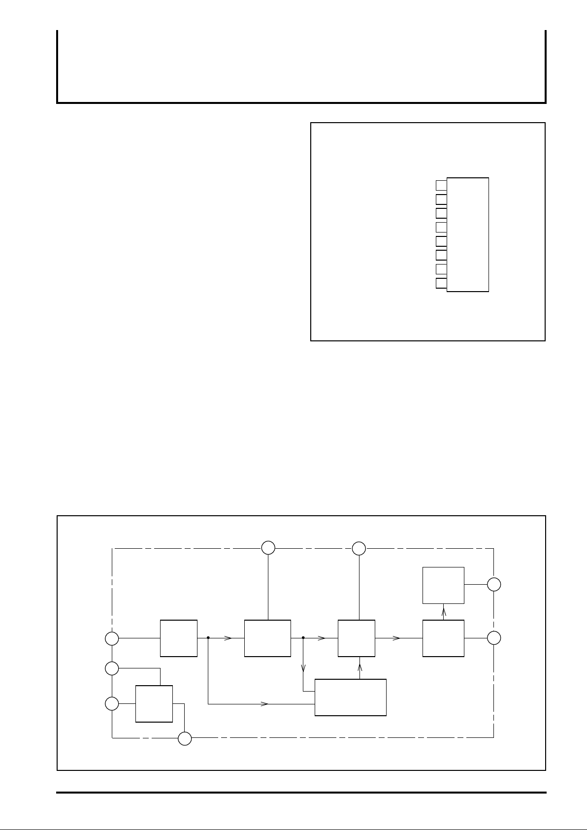
PIN CONFIGURATION(TOP VIEW
Time constant
Stabilized voltage
(+)GND
(–)Power supply
Current limit resistance
Integration capacitance
Input
Output
1
2
3
M51970L
4
5
6
7
8
Outline 8P5
BLOCK DIAGRAM
2
Input
4
GND
(–)Power
suppl
5
Stabilized
power
supply
Stabilized voltage
Amplifier
3
Time constant
1
Mono
multi-
vibrator
Integrated capacitance
8
Integrator
Overshoot
prevention circuit
Current
limit circuit
Current
amplifier
Current limit
7
resistance
6
Output
Page 2
ABSOLUTE MAXIMUM RATINGS(Ta=25°C unless otherwise noted
)
)
)
(2)
(1)
MITSUBISHI <CONTROL / DRIVER IC>
M51970L
MOTOR SPEED CONTROL
Symbol
Vcc
I
6
I
3
Supply voltage
Sink current into pin
Source current from pin
Parameter Conditions
6
3
With printed circuit board mounted (copper foil of 4.5 x 5.5
PdF
Power dissipation
cm in area, thickness of 35µ, printed circuit board of 2.0
mm in thickness)
K
θF
Topr
Tstg
Thermal derating
Operating temperature
Storage temperature
ELECTRICAL CHARACTERISTICS(Ta=25°C, Vcc=9V unless otherwise noted
Symbol Test conditions UnitParameter
CC Supply voltage range
V
CC
I
VS
VTH
RIN
ISC
T
τ
RegRegTCN
Circuit current
Stabilized output voltage
Input threshold voltage
2
Input impedance
Output limit current
6
One-shot pulse width
Motor speed stability for Vcc
VCC VCC = 4 – 15V
Motor speed stability for load
L
Motor speed stability for temperature
Ta = -20 – +75˚C
Except for output drive current
RSC = 27Ω
Rτ = 75kΩ, Cτ= 22,000pF
Ta = -20 – +75˚C
Ratings
18
40
-3
550
5.5
-20 – +75
-40
– +125
Limits
Min. Typ. Max.
18
2.5
3
1.8
-50
4.2
20
375
–
4.5
2.0
0
7.9
27
395
8
2.2
50
12
35
415
±0.1
±0.1
±10
Unit
V
mA
mA
mW
mW / °C
°C
°C
V
mA
V
mV
kΩ
mA
µs
%
%
ppm/˚C
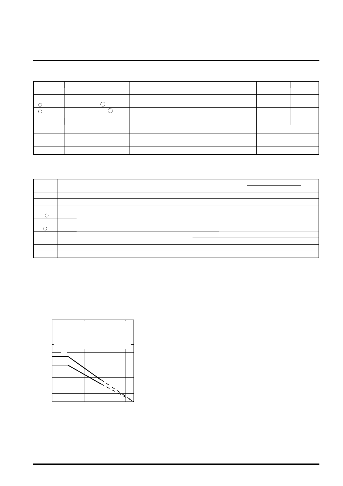
TYPICAL CHARACTERISTICS(Ta=25°C unless otherwise noted
Thermal derating (Maximum rating)
1000
(1)IC only
900
(2)With printed circuit board mounted
(copper foil of 4.5 x 5.5 cm in area,
800
thickness of 35µ, printed circuit board
700
of 2.0 mm in thickness)
600
500
400
300
Power dissipation Pd (mW)
200
100
0
0 25 50 75 100 125
Ambient temperature Ta (°C)
The data on the next page was measured with the
following constants in the “Application Circuit Example”
given below.
R1=100kΩ, R2=30kΩ, CF1=1µF, CF2=4.7µF, RF=4.7kΩ,
Rτ=75kΩ, Cτ=22,000pF, RSC=56Ω, number of tachogenerator poles; 10 poles. Motor speed - ambient
temperature characteristics is measured with Rτ and Cτ
put out of the temperature test chamber.
Page 3

MITSUBISHI <CONTROL / DRIVER IC>
)
M51970L
MOTOR SPEED CONTROL
Rotating speed–Supply voltage characteristics Rotating speed–Motor torque characteristics
3060
No load
3055
Rotating speed N (rpm)
3035
01020
Supply voltage Vcc (V)
3060
3055
Vcc = 6V
Rotating speed N (rpm)
3050
0 50 100
Torque T (g-cm
Vcc = 9V
Rotating speed–Ambient temperature characteristics Circuit current–Supply voltage characteristics
3060
3055
Vcc = 9V
No load
5
Except for sink
current to pin
4
3
2
6
Rotating speed N (rpm)
3050
020
-20 40 60 80
Ambient temperature Ta (°C)
APPLICATION CIRCUIT EXAMPLE
Motor rotating speed control circuit
+
10µ
Rτ
Cτ
R2
G
Tacho-generator
R
1
2
3
+
CF1
4 8
M51970L
1
5
Circuit current Icc (mA)
1
0
01020
Supply voltage Vcc (V)
F
R
+
CF2
6
M
7
Motor
VCC
R
SC
Page 4

(Note 1) How to determine Rτ and Cτ
This constant determines the motor rotating speed. If the motor
rotating speed and the number of poles in the tacho-generator are
assumed to be N and P,
expression is generally established. Putting Rτ in the range of
10kΩ to 500kΩ, select the constant according to the required
rotating speed.
NP
respectively, the following relational
1
=
1.17Rτ Cτ
MITSUBISHI <CONTROL / DRIVER IC>
M51970L
MOTOR SPEED CONTROL
Tacho-generator output frequency–
Connection resistance characteristics of pin
10000
5000
ISC
0.022
µF
=
0.01
µF
70
C
τ
=4700pF
µF
0.7(V)
RSC
200 300 500
3000
2000
1000
700
500
300
200
Tacho-generator output frequency NP (Hz)
100
10 100
(Note 2) How to determine RSC
According to the relation with maximum current ISC flowing to pin ,
the following relational expression is generally established. Set I
in such a way that the value cannot exceed the maximum rated
value of the power dissipation of the M51970L when the supply
voltage and temperature arrive at their maximum values.
0.047
0.1
µF
20 30 50
Connection resistance Rτ (kΩ) at pin
1
1000
1
6
SC
Maximum drive current at pin –
6
current limit resistance characteristics
50
6
40
30
20
10
Maximum drive current at pin
0
0 100 200
20 40 60 80 120 140 160 180
Current limit resistance RSC (Ω)
(Note 3) How to determine CF1, CF2 RF
Select CF1 and CF2 RF according to the inertia of motor and
required rising characteristics.
 Loading...