

Page 1

M491B
SINGLE-CHIP VOLTAGE SYNTHESIS TUNING SYSTEM
WITH 1 ANALOG CONTROL
.
16-STATION MEMORY - 7-SEGMENT LED
DISPLAY
.
VOLTAGESYNTHESIZER: 13 BITS
.
4-BANDPRESETCAPABILITY
.
NON-VOLATILEMEMORY : 304 BITS
- 16 WORDS OF19 BITS FORTUNINGVOLTAGE(13 bits)- BAND (2 bits) - FINEDETUNING (4 bits)
4
- 10
MODIFYCYCLESPER WORD
- MIN 10 YEARSDATARETENTION
.
PCM REMOTE CONTROL RECEIVER : DECODES SIGNAL TRANSMITTEDBY M708
.
VOLUMED/A : 6-BITRESOLUTION/ 8kHz
.
MEMORYSKIP FUNCTION
.
AUTOMATIC SEARCH WITH DIGITAL AFT
CONTROL
.
FINE DETUNING D/A ACTING ON AFT DISCRIMINATOR (16 steps) WITH SEPARATE
STORAGE FOR EACH MEMORY POSITION.
ALTERNATIVELYIT CAN BE USED TO CONTROL BRIGHTNESS OR COLOUR SATURATION
.
MANUAL SEARCH WITH DIGITALAFT CONTROL
.
MANUALSEARCHWITH LINEAR AFT
.
SWEEPSEARCHDISPLAYOUTPUT
.
SUPPLYVOLTAGES : VDD= + 5V,
=+ 25VFOR THE MEMORY
V
PP
.
CLOCKOSCILLATOR: 445TO 510kHz
.
INTEGRATED DIGITAL POWER ON RESET
(no externalinitializationcircuitry required)
DESCRIPTION
The M491B is a monolithic N-MOS LSI circuit including a Floating-gate Non-Volatile Memory for
storage of up to 16stations. Tuning of the station
is performedwith a 8192 step D/Aconverter,using
the principleof voltagesynthesis.It is designedfor
7-segmentLED displays. Direct memoryselection
is possibleonlyfromremotecontrol whileUp/Down
memory scanningis possible on the set and also
from remote control. An option input for 8 or 16
stations is available. The circuit also includes a
PCM remotecontrol receiveroperating in conjunc-
tionwith the transmitterM708. The highly reliable
transmissioncode ensureserror-free signal detection even in presence of high noise conditions.
Search of the station is possible in automatic or
manual modes. The circuit can operate with a
DigitalorLinearAFTcontrol.TheDigitalAFTmode
isnecessary for automaticsearch and requires an
external circuit (TDA4433 or equivalent,e.g. dual
comparatorplus TVstationdetector)toconvertthe
AFC-S-curveintoan Up/Down command.Finetuning(detuning)is alsopossiblewithdifferentmodes
ofoperation.Thecircuitisassembledin 40-pindual
in-lineplastic package.
DIP40
(Plastic Package)
ORDER CODE : M491B1
PIN CONNECTIONS
(GND)
V
SS
MEMORYSUPPLY
MEMORYTIMING
FINE TUNING D/A
TUNINGD/A
DIGITALAFTSTATUS
OSC. IN
OSC. OUT
V
TEST
I.R.INPUT
AFT1
AFT2
SWEEPDISPLAY OUT
VOLUMED/A
LINEARAFT DEF.
DIGITALAFTEN.
1
2
3
4
5
6
7
8
9
DD
10
11
12
13
14
15
16
17
18
V3
19
V2
20
V1 X4
40
39
38
37
36
35
34
33
32
31
30
29
28
27
26
25
24
23
22
21
VHFI
VHFIII
CATV
UHF
SEGM.h + i
SEGM.g
SEGM.f
SEGM.e
V
(GND)
SS
OPT.8/16
SEGM.d
SEGM.c
SEGM.b
SEGM.a
MAINSON/OFF
MAINSON OPTION
X1
X2
X3
491B-01.EPS
September 1992
1/16
Page 2

M491B
FUNCTIONAL DIAGRAM
+12V
UP
AFC-Scurve
(AFT1)
(AFT2)
DOWN
PP
V (25V)
OSC
445 to 510MHz
OSC
+5V
V
I V
or 8160
TDA2320
TEST
OUT
IN
SS MT MS
DDR
TUNING D/A
FINE TUNING D/A
VHF I
4
5
7 89 1011
1 23
31
32
SS
V
OPT. 8/16
4.5 to 13.2V
BAND OUT
UHF
CAT V
VHF III
39
40
b
a
f
h
37
38
c
g
d
e
i
AUTO SEARCH STOP
DIGITALAFT
SWEEP DISPLAYOUT
AFT1
14
DIGITAL AFT STATUS
AFT2
6
12
13
M491B
27282930333435
a
b
c
DIGITAL AFT ENABLE
17
d
LINEAR AFTDEFEAT
16
e
VOLUME D/A
MAINSON/OFF
MAINSONOPTION
15
25
26
23
24
X1 X2 X3 X4
181920 2122
V2 V3
V1
36
f
g
h - i
2/16
445 to
M708
510MHz
491B-02.EPS
Page 3
M491B
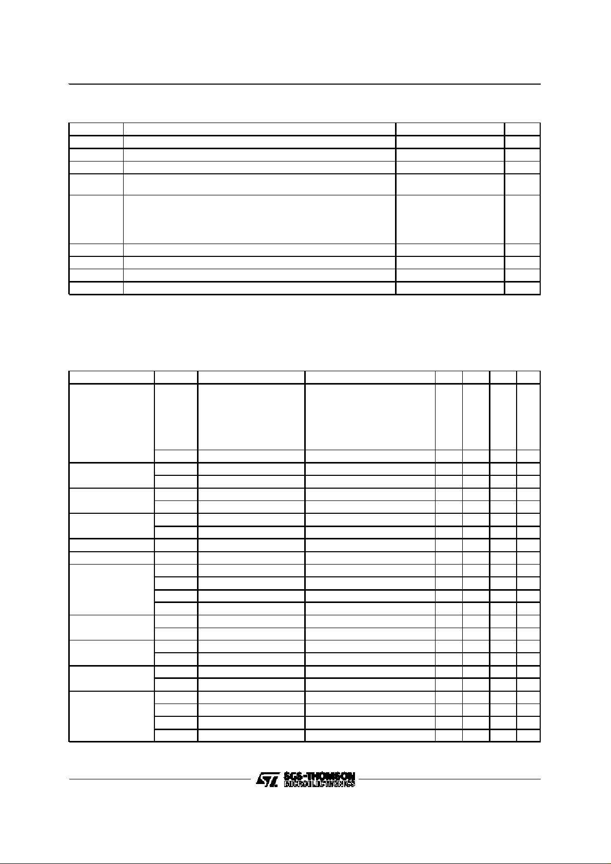
ABSOLUTE MAXIMUM RATINGS
Symbol Parameter Value Unit
V
DD
V
PP
V
V
O (off)
I
OL
t
pd
P
tot
T
stg
T
op
Stresses above thoselisted under”Absolute Maximum Ratings” maycause permanent damage to the device. This is a stress rating only and
functional operation ofthe device at these or any other conditions above those indicated in the operational sections of thisspecification is not
implied. Exposure to absolute maximum rating conditions for extended periods may affectdevice reliability.
DC ELECTRICALCHARACTERISTICS
(T
amb
2-Memory Supply I
3–Write Timing Out
4–Fine Tuning D/A
5–Tuning D/A
6–Digital AFT Out
9–Power Supply I
11–I.R. Input V
12–AFT1
13–AFT2
14—Display Out
15–Volume D/A
16–Linear AFT Out
17–Digital AFT Enable
Supply Voltage – 0.3, + 7 V
Memory Supply Voltage – 0.3, + 26 V
Input Voltage – 0.3, + 15 V
I
Off State Input Voltage (except pin 3)
Pin 3
Output Low Current
Led Driver Outputs
Pins 6 – 14
Pins 4 – 5
All Other Outputs
15
28
mA
20
20
7.5
5
Max. Delay between Memory Timing and Memory Supply Pulses 5 µs
Total Package Power Dissipation 1 W
Storage Teperature – 25, + 125 °C
Operating Temperature 0, + 70 °C
=0 to + 70°C, VDD= +5V unless otherwisespecified)
Pin Symbol Parameter Test Conditions Min. Typ. Max. Unit
Memory Supply Current VPP= 25V
PP
R Pull Down Resistor 25 kΩ
V
I
O (off)
I
O (off)
V
V
I
O (off)
V
V
Output Low Voltage VDD= 4.75 V, IOL= 2.5 mA 8 V
OL
Output Leakage Current VDD= 4.75 V, V
VDD= 5.25 V, V
OL
OL
VDD= 4.75 V, IOL= 5 mA 1 V
VDD= 4.75 V, IOL= 20 mA 1.5 V
VDD= 5.25 V, V
Supply Current VDD= 5.25 V 100 mA
DD
Peak-to-Peak Voltage 0.5 13.2 V
IPP
Input low Voltage VDD= 5.25 V 1.5 V
IL
Input High Voltage VDD= 5.25 V 3.5 V
IH
Input Low Current VDD= 5.25 V, VIL= 1.5 V –0.4 mA
I
IL
R Pull-up Resistor 30 kΩ
V
I
O (off)
V
I
O (off)
V
I
O (off)
V
V
I
OL
OL
OL
IL
IH
IL
VDD= 4.75 V, IOL= 20 mA 1.5 V
VDD= 5.25 V, V
VDD= 4.75 V, IOL= 4 mA 1 V
VDD= 5.25 V, V
VDD= 4.75 V, IOL= 1 mA 0.4 V
VDD= 5.25 V, V
VDD= 5.25 V, VIL= 0.8 V –0.4 mA
R Pull-up Resistor 30 kΩ
Write Peak
Average
Erase Peak
Average
Read Peak
Average
= 26 V 100 µA
OUT
= 13.2 V 50 µA
O (off)
= 13.2 V 100 µA
O (off)
= 13.2 V 100 µA
O (off)
= 13.2 V 50 µA
O (off)
= 13.2 V 50 µA
O (off)
42
12
9
5
8
2.5
0.8 V
2.0 V
V
V
mA
491B-01.TBL
491B-02.TBL
3/16
Page 4
M491B
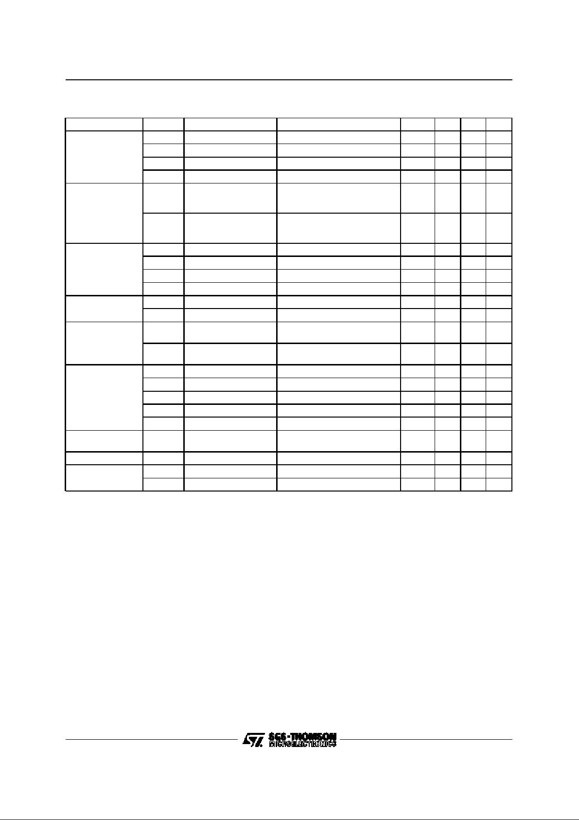
DC ELECTRICALCHARACTERISTICS (continued)
Pin Symbol Parameter Test Conditions Min. Typ. Max. Unit
18–19–20
V3
Keyboard
V2
}
In
V1
21–22–23–24
X4
Keyboard
X3
}
X2
Out
X1
V
IL
V
IH
I
IL
R Pull-up Resistor 30 kΩ
V
OL
I
O(off)
1.5 V
3.5 V
VDD= 5.25 V, VIL= 0.8 V –0.4 mA
VDD= 4.75 V, IOL= 1 mA 0.4 V
V
= 5.5 V 25 µA
O (off)
V
IL
25–Mains On Enable
26–Mains On/Off
31–Z2
32–Z1
MPX for
Display Out
37–UHF
38–CATV
39–VHFIII
40–VHFI
27-28-29-30-3334-35 Display Out
36-Display Out V
31-Memory 8/16
}
B
A
N
D
DESCRIPTION(All timingsat f
PIN 1 : V
SS
V
IH
I
IL
R Pull-up Resistor V
V
OL
I
O
V
OL
I
O(off)
V
OL
V
OH
V
IL
V
IH
I
O(off)
V
OL
OL
V
IH
V
IL
= 500kHz)
clock
Thesubstrateof theIC isconnectedto thispin.This
is thereferencepin for all parameters of the IC.
PIN 2 : MEMORY SUPPLYVOLTAGE
A supply voltage of 25 ± 1 V has to be appliedto
this pin duringthe modifyand read cycles.
MODIFYCYCLE
Amodify cycleconsistsof threesteps :
1.All”1”sarewritten inthebitsoftheselectedword.
2. All bits of the selectedword areerased (all ”0”s)
3. Thenew contentis written.
Thus a constantaging of all thebits of theword is
0.8 V
2.4 V
VDD= 5.25 V –0.4 mA
= 0.8 V 30 kΩ
IL
VDD= 4.75 V, IOL= 100 µA 0.4 V
VDD= 4.75 V, VO= 0.7 V –1.6 mA
VDD= 4.75 V, IOL= 1 mA 0.4 V
VDD= 5.25 V, V
VDD= 4.75 V, IOL= 1 mA 3 V
VDD= 4.75 V, IOH= – 150 µA 2.4 V
VDD= 5.25 V, V
VDD= 4.75 V, IOL= 20 mA 1.5 V
VDD= 4.75 V, IOL= 30 mA 1.5 V
= 13.2 V 50 µA
O (off)
3 V
= 13.2 V 50 µA
O (off)
2.0 V
0.3 V
0.8 V
obtained.
During both write and erase cycles the memory
status is checked continuously ; therefore after
eachwriteorerasepulseareadoperationiscarried
out. The write orthe erase operationsare stopped
as soon as the result of theread operationis valid.
WRITE CYCLE. The peak of the current flowing
throughpin 2 duringa writeoperation is shown in
fig. 1, while fig. 2 shows the envelopeof thesame
current.
The typical write time is 3-4 ms for the firstcycles
and increasesto about30 ms after1000 cycles.
491B-03.TBL
4/16
Page 5
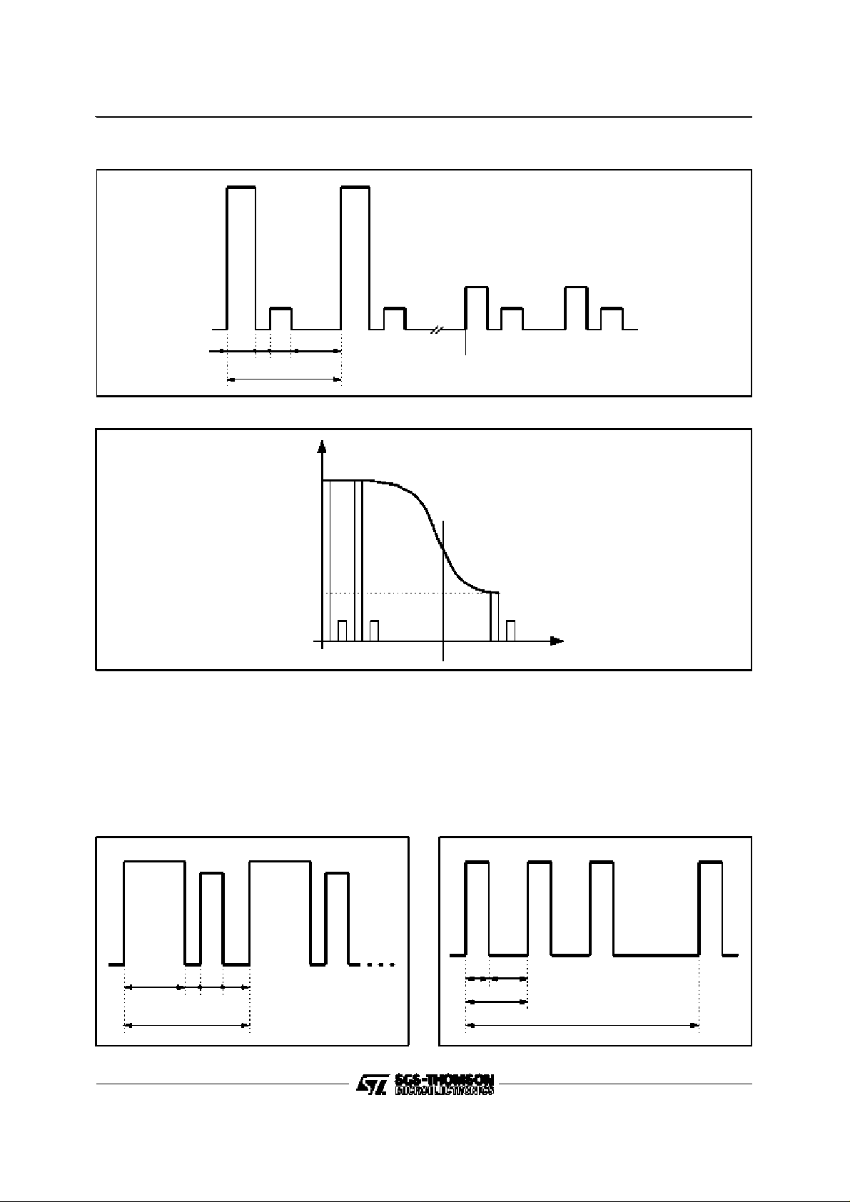
Figure1
M491B
40mA
12mA
6mA
64 32 44 116µs
256µs
Figure2
I (mA)
40
12
5
Typ.max. 20msec Typ.max. 8msec
ERASECYCLE
Figure3 showsthe timingand thewaveform of the
current flowing through Pin 2 during the erase
operation. The peak current is 7mA (max) during
the erase cycle and 6mA (max) during the read
cycle. The typical erase time is 10ms for a new
device and increases with the number of modify
Afterabout30msec
491B-03.EPS
t (ms)
491B-04.EPS
operationsup to200ms after 1000 cycles.
In orderto protect the memoryincase of failureof
some bits the modify operation is stopped after
1sec.
READCYCLE
Figure 4 shows the waveformofthe currentduring
a read operation.
Figure3
128µs 52
32 44
256µs
7mA
6mA
Figure4
491B-05.EPS
44
6mA
84µs
128µs
480µs
491B-06.EPS
5/16
Page 6

M491B
PIN 3 : MEMORYTIMINGOUTPUT
This output gives the timing for the pulses to be
appliedat Pin 2 during the modify and read cycles.
The output consists of an opendrain transistor.
PIN 4 : FINE TUNING D/A(see Figure 5)
A D/A converter with16-step resolution and a frequencyof15kHzcanbeusedtogeneratea voltage
which,iffedtoavaricapdiodeinparalleltothe AFC
discriminator, willdetune the receiver bya small ∆f
whilemaintainingthe actionofthe DigitalAFT.This
output can be used in conjunctionwithboth Linear
and DigitalAFT modes of operations.
The Fine tuningfunction operates as follows :
- At the start of any automatic or manualsearch,
the output is set at the mid range.
- Whenthe search has been completedit ispossible to operateon FT ± commands.
The storecommand memorizes this information
Figure5
together with the 13 tuning voltage bits and 2
informationbits.
- Modification time of FT D/A is of 1 step every
200msifissuedlocallyorevery2receivedsignals
from Remote control transmitter.
PIN 5 : TUNINGD/A (see Figure 6)
13
A 2
= 8192 step pulse modulated signal for the
tuning voltageis available on thispin.
Pulse modulation is implementedby combination
of a rate multiplier andpulse width principle.
With a tuning voltage increasing from zero, the
number of pulses increases continuously up to
8
2
= 256 ; starting from this point the number of
pulses remainsthe same but thepulsesget larger
until they reach the maximumcontentof theinternal counter.The output consists of an open drain
transistorwhich offers a low impedance to ground
when in theON state.
64µs
9 7
V
OUT
FineTuning Output
FT
FT
Mid
Range
491B-07.EPS
6/16
Page 7

Figure6
M491B
D/A
Converter
V
A
V
A
V
B
V
C
PIN 6 :DIGITALAFT STATUSOUTPUT
(see Figure 7)
This outputshowsthe statusof the digitalAFT.Itis
low when the digital AFT is enabled and it can
directly drive a LED.
The outputconsistsof anopen drain transistor.
PINS7 & 8 : OSCILLATORINPUT/OUTPUT
(see Figure8)
The frequency of the clock oscillator should be
between 445and 510kHzusingalow-costceramic
resonator. In these conditions the value of the
referencefrequencyof the transmittercan beinthe
same range. In otherwords the transmitterand the
receiver can operate with different reference frequencies.
Figure7
max.13.2V
6
Varicap
V
down-up
B
V
C
Figure8
7 8
455to
510kHz
100pF100pF
PIN 9 : V
DD
The supply voltage has to be comprised in the
range 4.75 to 5.25V. When it is applied an internal
poweron resetof 0.5sis generated.
The memoryposition 1 isautomatically read if the
mains on option input(Pin 25) is grounded.
PIN 10 : TEST
Thispinis usedfor testingandhastobeconnected
to V
.
SS
PIN 11 : I.R.SIGNAL INPUT (see Figure9)
The integrated receiver decodes signals transmit-
ted by M708, address 9.
The minimumsignalto beappliedis 0.5V peak-topeak. (AC-coupled).
The receiver input section performs the following
tests on the incomingsignal to achievethe necessarynoise immunity :
- measurement of the pulse distance (time base
synchronization)
491B-09.EPS
491B-08.EPS
491B-10.EPS
7/16
Page 8

M491B
- checkof thepositionofthe received bits opening
windowat the time bases
- checkof theparity bit
received word is rejected and not decoded. If the
receivedsignal is acknowledgedas a valid word it
is stored an decoded.
- checkof theabsenceofpulsesbetweentheparity
bit and the stop pulse
- checkof noiselevel;the receiverchecksparasitic
transientsinside and outsidethe time windows.
If the above test conditions are not fulfilled, the
The end of transmissionwill be acknowledged by
receivingthe endoftransmissioncodeorbymeans
of an internal timer if the transmission remains
interruptedfor morethan about 550ms.
Figure9
TDA2320
or TDA8160
R C
M491B
Supply Voltage of
TDA2320
5
12
R C
2.2kΩ
10kΩ
4.7nF
4.7nF
M491B REMOTECONTROLRECEIVER TRUTH TABLE. TransmitterM708 ; AddressCode 9
Command
Number
0 0 0 0 0 0 0 End to Transmission
1
2
3
4
5
6
7
8
9
10
11
12
13
14
15
16
17
18
19
20
21
22
23
24
25
26
27
28
29
30
C1 C2 C3 C4 C5 C6
1
1
0
1
0
1
1
1
0
1
0
1
1
1
0
1
0
1
1
1
0
1
0
1
1
1
0
1
0
1
0
1
0
0
1
1
0
1
0
0
1
1
0
1
0
0
1
1
0
1
0
0
1
1
0
1
0
0
1
1
I.R. Code
0
0
1
1
1
1
0
0
1
1
1
1
0
0
1
1
1
1
0
0
1
1
1
1
0
0
1
1
1
1
Function
0
0
0
0
0
0
0
0
0
0
0
0
0
0
0
0
0
0
0
0
0
0
0
0
1
1
1
1
1
1
0
0
0
0
0
0
1
1
1
1
1
1
0
0
0
0
0
0
1
1
1
1
1
1
1
1
1
1
1
1
0
Power On/Off
0
Mute On/Off
0
Memory 1
0
Memory 2
0
Memory 3
0
Memory 4
0
Fine Detuning Up
0
Fine Detuning Down
0
Memory 5
0
Memory 6
0
Memory 7
0
Memory 8
1
Memory Up
1
Memory Down
1
Memory 9
1
Memory 10
1
Memory 11
1
Memory 12
1
Manual Search Up
1
Manual Search Down
1
Memory 13
1
Memory 14
1
Memory 15
1
Memory 16
1
Volume Up
1
Volume Down
1
Memory Addressing
1
Digital AFT On
1
Band Sequential
1
Automatic Search
}
Mute
491B-11.EPS
491B-04.TBL
PINS 12& 13: AFT1-AFT2(STOP/AFTINPUTS)
These pins are enabled during the automatic
search and during normal operation, when the
digitalAFT is enabled (see descriptionof Pin 17).
8/16
The STOP/AFTinputs are also disabled internally
duringanyprogramorbandchangefortheduration
of the Mute signal.
Page 9

Thesepins workaccordingto thetruth table given below :
M491B
M491B Pin 12
TDA4433 Pin 2
H
L
L
H
M491 B Pin 13
TDA4433 Pin 6
These inputs have two different functionsdepending on whether the system is in the search or in
normal operation(AFT control).
The inputs have internalpull-up resistors of 30kΩ
typ.
A) Searchmode : afterdepressingthe Automatic
searchor presetkeys, thelevels of the signals
coming from the TDA4433, applied to these
pins,controlthe searchfunctionand determine
whenthesearchmuststop,i.e.aTVstationhas
been recognized.
The circuit operates in the following sequence
(see Figure 10 for reference):
1 - after pressing the search start key the
searchoccurs in the FASTUP mode.
2 - eventual transitions available on these
inputsareignoredduringthefirst15search
steps if the system is in the UHF or CATV
bands.
If the system operates in VHF I and III bands,
the first 60 search steps are ignored. The
acceptancedelay of 15 (60) search steps has
been introduced to prevent the system from
stoppingat theprevious station.
After this time the FAST UP speed is
automatically reduced to half during each UP
signal(MEDIUM UP = FASTUP/2).
A DOWN signal preceded by at least an UP
signal will set the search to MEDIUM DOWN
mode(FAST UP/4).
3 - the next UPsignal will switch the search to
SLOWUP speed (61Hz).
At this point the systems is in normal AFT
operation.
(referred to the tuning voltage)
L
H
L
H
Function
Up
Down
Middle
No Operation
B) Digital AFT operation : when a station is
perfectly tuned, the inputsignals coming from
TDA4433are at middle condition.
If the tuning moves lower than the threshold
below 38.9MHz,the Pin 12 is put H and Pin 13
is put L ; the 13 bit internalcounter is moved
SLOW UP speed to increase the varicap
voltage.
When a detuning occurs in the opposite
direction the input 12 goes Low and 13 goes
High and the tuning voltage falls at VERY
SLOWDOWN speed (7.6Hz).
The increaseor decreaseof the tuning voltage
is stopped as soon as the input returns to
middle conditions.
ThereforeduringnormaloperationPins 12and
13 actas digital AFT control commands.
C) Recall from memory : whenthe digital AFT is
enabled and data is recalled from Memory, a
fixed valueof 8steps (≈ 31.2mV)is subtracted
from the tuningvoltage.
This corresponds to a detuning of 0.6MHz
(UHF) andof 0.3MHz in VHFIII into that part of
the IF responsecurvewhichcorrespondsto the
fully transmittedsideband.
At this point the AFT operation takes over as
describedinpointBaboveandtheexacttuning
is achieved in about0.2 sec.
This feature increases the AFT capture range
and fullfills the stability requirements of the
tuner, voltage references and the D/A
converter.
If theDigitalAFTis disabled(Pin 17at V
memory contentis read withoutany change.
SS
461B-05.TBL
), the
9/16
Page 10

M491B
Figure10
34 35 36 37 38MHz
IF
RESPONSE
SEARCH
DIRECTION
SIGNALS
ON
TDA4433
SEARCH
START
AFC
THESHOLD
Pin6
Pin2
FAST UP
S1
139.0MHz
38.8MHz
TRANSMITTER
IDENTIFICATION
MEDIUM UP
S2= 0.5 S1
DIGITAL
INFORMATION
38.8
39
40MHz
MEDIUMDOWN
S3 = 0.25 S1
NORMALAFC POSITION
t
40 39
38.8
VARICAP VOLTAGE
38.8
MHz
SLOW UP
S3 = 67Hz
NORMAL AFC
OPERATION
STOP
PIN 14 : SWEEPSEARCHDISPLAYOUTPUT
This output, which is normally Low, goes High
during automaticsearch automaticpreset et intervals of 160ms for about 40msto blank the LED of
band display.
Figure11
BAND
LEDS
V
SS
10/16
PIN 15 : VOLUME D/AOUTPUT
This output delivers a square wave signal of 7.8
kHzand dutycycle variable in 63 steps.In case of
a continuouscommand for varyingthe volume, the
duty cycle ischangedat the rate of the transmitted
signal (approximately every 102ms with f
500kHz)or every 112ms if issued locally.
Overflowand underflow protection are provided.
The volume output can be switched to V
reset to the previouslevel by means of the Mute
On/Off command. It is also reset by the Volume
Up/Downand the MainsOn/Off commands.
The volume is muted for about 1s at each mains
onandoffcommandduring thepoweron resettime
and program change (0.5s).
At the first power on reset of V
the volume D/A
DD
is setat the level 21/64. Thelast level is preserved
until V
491B-13.EPS
isnot removed.
DD
SS
t
491B-12.EPS
=
ref
and
Page 11

M491B
PIN16 :LINEAR AFT DEFEATOUTPUT
This output is normallyHighand goesLowwhen a
Manual Up/Down command is issued.
It returns High with a 1 second delay from the
release of the key, in order to give the user the
possibilityof the tuningadjustmentwithoutthe AFT
intervention.It goes Low for 0.5s during program
change.
Figure12
MAN UP/DOWN
KEY PRESSED
LINEAR AFT
DEFEAT OUTPUT
MAN UP/DOWN
KEY RELEASED
1sec
PIN 17 :DIGITALAFT ENABLEINPUT
If this input is connected to V
(GND), the digital
SS
AFT loop is always disabled. If pin17 is left open
or isconnectedto V
, thedigital AFT is automat-
DD
ically enabled at power on. When a manual
up/downsearchcommandisissued,thedigitalAFT
loop isdisabledandthe digitalAFTstatusoutputis
inhibited.
The digitalAFT loop is restoredby the commands:
DigitalAFTon/Automaticsearch/Automaticpreset.
PINS18-19-20-21-22-23-24:
KEYBOARDMATRIX (seeFigure 13)
A command is accepted if the corresponding con-
tacthas beenclosed for a minimumtime of 30ms.
Local input commands and I.R. commands have
the same priority.
If a completeI.R.commandhas been received,the
local inputs are blocked until the command has
been executedand the”end of transmissioncode”
generated.
Viceversa an I.R. signal cannot be decoded until
an issuedlocal command has been executed.
MEMORYUP/DOWN
Depressingone ofthesetwocommands,thememory position isstepped in the UP or DOWN direction.
If the key is keptclosed,the channelsare stepped
UP/DOWNevery0.5secondor every5 commands
from the transmitter.
The memorylocations9 to 16 are jumped if pin 31
is at GND level.
491B-14.EPS
BAND SELECTION
The bandscan be selected either directlyor with a
step-by-stepcommand inthe followingsequence:
VHF I
CATV
VHF III
UHF
VHF I and so on
Only one band change is performed at each acceptedcommand.
Disabledbands are automaticallyskipped. A band
canbedisabledconnectingthecorrespondingoutput to V
SS
.
Figure13
V1 V2 V3 X1 X2 X3 X4
20
MEMORY
UP
MEMORY
DOWN
MAN SEARCH
UP
MAN SEARCH
DOWN
DIGITAL
AFT ON
AUTOMATIC
SEARCH
FT.
UP
FT.
DOWN
19 18
BAND
SEQ.
POWER
ON/OFF
VOLUME
UP
VOLUME
DOWN
BAND
I
BAND
III
BAND
UHF
BAND
CATV
AUTOMATIC
PRESET
MEMORY
ADDRESSING
STORE
MUTE
23 22 2124
491B-15.EPS
11/16
Page 12

M491B
SEARCHMODES
4 modesare available:
a) Automatic search
b) Automatic preset
(digiatlAFT)
c) Manualup/down(digital and linear AFT)
d) Manual up/down(linear AFT)
a) AUTOMATICSEARCH.The searchstarts from
the actual tuning and band position. During the
searchthe tuning voltage is always changingfrom
lower to highervoltagelevels.When the end of the
bandisreachedthesearchrestartsfromthebeginning of the next band after a 480 ms interruption
with the sequenceof step-by-stepband selection.
Disabledbandsare automaticallyskipped.
The search is stopped when the first station is
foundor if a channel selectioncommand is given.
Stop of the automatic search is determined by the
STOP/AFTinputscontrolledby theTDA4433which
converts the AFC-S-curve into an up/down command.
At the end of the search the up/down command
controlsthe correcttuning acting on the counter of
the voltage synthesizer(DigitalAFT).
It isimportanttocall the attentiontotheDigitalAFT
capturerangewhichislargerthanthenormallinear
AFT as shownin fig.14.
Figure14
LINEAR AFT
CAPTURE RANGE
DIGITAL AFT
CAPTURE RANGE
Additionallythe use of the DigitalAFT allows storage of the tuning informationcorrespondingto the
zero point of the AFC-S-curve. This cannot be
guaranteedusingtheLinearAFTmethodonly.The
latter is a cheaper system, because it does not
require the use of the TDA4433but it cannot guarantee what described above.
As a resultoftheuseoftheDigitalAFT, therequirements for stability of the tuner, of the reference
voltage sourceand of stability of the D/A converter
are less critical.
Tuning speed in automatic search, if no station is
found is :
VHFI 8 second
VHFIII 8 second
UHF 32 second
CATV 32 second
The tuning and band information can be stored
using the store/memory addressing command.
Thesearchcan be stoppedby amemory selection
command.
b) AUTOMATIC PRESET. The search starts from
the lowest memory address, tuning voltage and
VHF I band as described in automatic search
mode.
Whenan active station is encountered, the corresponding tuning and band informationis automaticallystored in theNon-VolatileMemory.
Afterwardsthe system starts tosearch forthe next
station.The cycleis repeated until all bandshave
been scanned or the tuning information has been
stored into all addresslocations. After completing
thiscycle the system reads out the tuning informationof the lowest address.
c) MANUAL UP/DOWN WITH DIGITAL AND LINEAR AFT (pin 17 at V
). Holding one of these
DD
commands pressed, the tuning voltage is increasedor decreased.
During this operation, the Digital AFT is automatically defeated and can only be reconnected with
the ”AFT on” command or byan Automaticsearch
orpreset command.
The search speed is kept at minimum (there isno
incrementwith the time)
Band
VHF I
VHF III
UHF
CATV
seconds
491B-16.EPS
In caseof commandreceivedfromremote control,
Sweep Timefor the
Complete Band
128 seconds
128 seconds
512 seconds
512
16
Number of Tuning
Steps/Second
64
64
16
the counter is increased/decreasedevery two receivedcommands.
Nobandswitchingisprovidedat the upper orlower
tuningpositions.
Thevolume is automaticallymuted 3 secondafter
the key pressure is immediately restored at the
releaseof the key.
d)MANUALUP/DOWNWITHLINEARAFT(pin17
at V
). When this control is used the Digital AFT
SS
isdisabled.
TheLinearAFToutputgoeslowafteranupordown
commandis issued and remains Lowfor 1 second
after the releaseof the key.
12/16
Page 13

M491B
The volume is automatically muted for 3 seconds
afterthe key pressure and is immediately restored
at the release of thekey.
Tuningspeeds are as follows:
- FINE TUNING UP/DOWN
See description of pin 4.
- DIGITALAFTON
See description of pin 17.
- VOLUMEUP/DOWN
See description of pin 15.
- MAINS ON/OFF
See description of pins 25 and 26.
Band
VHF I
VHF III
UHF
CATV
Number of Tuning Steps Second
Time 0 After 1 s After 2 s After 3 s
64
64
16
16
128
128
32
32
256
256
64
64
512
512
128
128
STORECOMMANDS
2 modesof operationsare available.
a)store
b)memoryaddressing
In order to protect the memory, the store function
is internallydisabled after one storecycle.
It is enabled after a program change or a tuning
operation (it is not disabled by the Digital AFT
control).
a) STORE. The tuning information (Tuning D/A,
Fine tuning D/Aandband) is stored in apreviously
selected memory address when this command is
issued.
b) MEMORY ADDRESSING. The tuning information can alsobestoredwith this command followed
by thememory positionselection.
When this command is accepted all the memory
LEDs are blanked.
Selectionof the memory positioninitiatesthestore
operationsand restoresthe display.
MUTE ON/OFF
See descriptionof pin 15.
PIN 25 : MAINSON OPTIONINPUT
If connected to V
automaticallyswitchedonwhen V
(GND) the Mains output is
SS
isappliedand
DD
memory 1 is read.
If it is connectedto V
thecircuit goes in stand by
DD
condition.
PIN 26 : MAINSON/OFF OUTPUT
Switch on of the set is controlledby the Mainson
command issued for more than 0.3 s. The output
transistoris set in theoff condition to drive through
an integrated pull-up resistor, an external NPN
transistor.
Figure15
+5V
At each Mains on command a memory read out
occurs.AV
(+25 V)isrequiredforthisoperation,
PP
a 1 second delaystarts when the mains output is
switchedoff. For a correct reading of the memory
the V
supplyvoltage must reach the value of 25
PP
V within 1 secondafter a Mainson command.
491B-06.TBL
In caseof automaticswitch on at poweron caused
bypin 25 at GND, the total delay is of 1.13 second
(0.13s for V
power on reset plus 1 second for
DD
mains on).
TheMains on/off command,ifrepeated, willswitch
the output on (setoff).
Thelast addressinformationis preserved untilV
ispresent.
NextMains on command will switch the set at the
previously selected memory address and a read
operationwill be performed.
PINS27-28-29-30-33-34-35-36:
MEMORYADDRESSOUTPUT
Thesepinsoperateasoutputonlyfordisplayofthe
selected memory location. Max drive capability is
of15 mA/1.2V with the exception of pin 36 that is
of30 mA/1.5 V.
Directmemory selectionis onlypossiblebyremote
control.Alocalmemoryup/downcommandisavailable in caseof emergency.
Pin32 mustbe grounded.
If pin 31 is grounded, the memory position 9 to 16
are skipped in case of memory up/down commands.
For normal operation pin 31 can be left open or,
better,connectedto V
DD
.
PINS31-32
Seedescriptionof pins 27 to 30 and33 to36.
PINS37-38-39-40 : BANDINPUT/OUTPUT
Theseoutputsareprovidedto selectupto 4 bands
viaexternal PNPs.
If one or more bands have to be skipped, the
correspondingoutputshavetobe short-circuitedto
V
.
SS
491B-17.EPS
DD
13/16
Page 14

M491B
Figure16
The relation between pins and bands are as follows :
Pin 37 = UHF
Pin 38 = CATV
Pin 39 = VHF III
Pin 40 = VHF I
INPUT/OUTPUT CONFIGURATION
max. 13.2V
491B-18.EPS
Output OpenDrain
Pins 3, 4, 5, 6, 14, 15, 16, 30, 33,34, 35, 36
OutputPush-pull
V
DD
26
Inputs with Pull-up Load
V
DD
Inputs/Outputs(std)
Pins37, 38, 39, 40, 21, 22, 23, 24
491B-19.EPS
(21, 22, 23, 24 are used only for testing purposes)
Oscillator
491B-20.EPS
IR Input
491B-22.EPS
V
DD
8
7
491B-23.EPS
V
DD
14/16
Pins12, 13, 17
18, 19, 20, 25, 31
491B-21.EPS
11
491B-24.EPS
Page 15
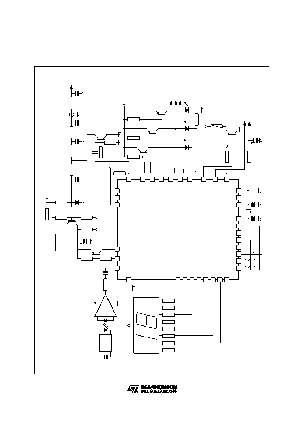
TYPICALAPPLICATION
Manual Searchwith LinearAFT (16 memoryoption)
TUNING
VOLTAGE
100nF
82kΩ
or
BSX93
100nF
56kΩ
150nF
47pF
33kΩ 33kΩ
100nF
2N3903
Ω
3.9k
+5V
+12V
10
kΩ
10
kΩ
BC177
10
3.3kΩ
1.5
kΩ
kΩ
5
8.2kΩ8.2kΩ8.2kΩ
373839
BC177
BC177
40
M491B
I
III
UHF
VOLUME
BC108
LINEARAFTDEFEAT
10µF
Ω
22k
ON/OFF
26
+12V
16
RELAY
+12V
5.6kΩ
15
0.68kΩ
14
17
R2
HIGH VOLTAGE
H
V (V) - 33V
R1(kΩ) =
R1
1.6kΩ1%
11mA
R2 =R1/4
33V
TAA550B
5.6
kΩ1%
Ω
82
k
F
22
µ
BC297
4.7kΩ
4.7nF2.2kΩ
+ 5V
kΩ
6.8
or 8160
TDA2320
9 3125
8 110
21222324 7
500kHz
100
100
pF
pF
M491B
2311
32
+12V
27
28
29
30
33
343536
7 x 0.68kΩ
181920
6 - PowerOn/Off
567
123
7 - VolumeUp
8 - VolumeDown
9
8
4
9 - Store
M708
445 to
510MHz
0.33
LOCAL COMMANDS
1 - MemoryUp
2 - MemoryDown
3 - SearchUp
4 - SearchDown
5 - Band Sequential
kΩ
491B-25.EPS
15/16
Page 16

M491B
PACKAGE MECHANICALDATA
40 PINS- PLASTICDIP
I
L
E
F
40
1 20
Dimensions
a1
b
b2
e3
D
e
21
Millimeters Inches
Min. Typ. Max. Min. Typ. Max.
a1 0.63 0.025
b 0.45 0.018
b1 0.23 0.31 0.009 0.012
b2 1.27 0.050
D 52.58 2.070
E 15.2 16.68 0.598 0.657
e 2.54 0.100
e3 48.26 1.900
F 14.1 0.555
i 4.445 0.175
L 3.3 0.130
b1
PM-DIP40.EPS
DIP40.TBL
Information furnishedis believed to be accurate and reliable. However, SGS-THOMSON Microelectronics assumes no responsibility
for the consequences of use of such information nor for any infringement of patents or otherrights of third parties which may result
from its use. No licence is granted by implication or otherwise under any patent or patent rights of SGS-THOMSON Microelectronics.
Specifications mentioned in this publication are subject to change without notice. This publication supersedes and replaces all
information previouslysupplied. SGS-THOMSON Microelectronics products are not authorized for use as critical components in life
support devices or systems without express written approval of SGS-THOMSON Microelectronics.
1994 SGS-THOMSON Microelectronics - All Rights Reserved
Purchase of I
2
I
C Patent. Rights to use these components in a I2C system, is granted provided that the system conformsto
Australia - Brazil - China - France - Germany- Hong Kong - Italy - Japan - Korea - Malaysia -Malta - Morocco
The Netherlands - Singapore - Spain - Sweden - Switzerland - Taiwan - Thailand - United Kingdom - U.S.A.
2
C Components of SGS-THOMSON Microelectronics, conveys a license under the Philips
2
the I
C Standard Specifications as defined by Philips.
SGS-THOMSON Microelectronics GROUP OF COMPANIES
16/16
 Loading...