

Datasheet M16C245M4-XXXGP, M16C245FG-GP, M16C245FC-GP, M16C245FA-GP, M16C245F8-GP Datasheet (Mitsubishi)
...Page 1

Preliminary Specification
Specifications in this manual are tentative and subject to change
Features
1-3
Mitsubishi microcomputers
M30245 Group
SINGLE-CHIP 16-BIT CMOS MICROCOMPUTER
1.0 Description
The M30245 group is a 16-bit microcomputer based on the M16C family core technology that uses the
high performance silicon gate CMOS process withan M16C/62 Series CPU core, and is packaged in a
100-pin, molded plastic QFP. They are single-chip USB peripheral microcontrollers meeting the
Universal Serial Bus (USB) Version 1.1 specification. These microcontrollers operate using
sophisticated instructions featuring a high level of instruction efficiency, making them capable of
executing instructions at high speed.
1.1 Features
• Number of instructions........................ 91
• Shortest instruction execution time..... 83ns f(XIN)=12MHz, Vcc=3V with no wait
• USB Features:..................................... 5endpointpairs(IN/OUT)
3.25KFIFO
Integratedtransceiver
Conforms to USB V1.1 Specification
• Frequency Synthesizer........................PLL for 48MHz clock
• Memory capacity................................. 64KROM/5KRAM
128KROM/10KRAM
128K Flash /10K RAM
• Supply Voltage.................................... 3.0 to 3.6V (f(XIN)=12MHz)
• Interrupts............................................. 21internaland5externalinterruptsources
4softwareinterruptsources
7 levels (including key input interrupt X 8)
• Multifunction 16-bit timer..................... 5 output timers+ 3 input timers
• UART................................................... 3X7/8/9,2X7/8/9/16/24/32bits;
Configurable for synchronous or asynchronous mode, I2S, I2C
• DMAC.................................................. 4 channels
• A-D Converter..................................... 10 bits X 8 channels
• CRC calculation circuit........................ 2 circuits with MSB/LSB selectable
• Watchdog timer................................... 1 line
• Key-on Wake up.................................. 8 inputs
• Programmable I/O............................... 84 lines (TBD)
• Clock-generating circuit....................... 2built-inclockgenerationcircuit
(built-in feedback resistor, and external ceramic or quartz oscillator)
1.2 Applications
USB peripherals, such as telephones, audio systems, office equipment, communications equipment,
portable equipment, scanners, and digital cameras.
Page 2
1-4
Preliminary Specification
Specifications in this manual are tentative and subject to change
Pin Configuration
Mitsubishi microcomputers
M30245 Group
SINGLE-CHIP 16-BIT CMOS MICROCOMPUTER
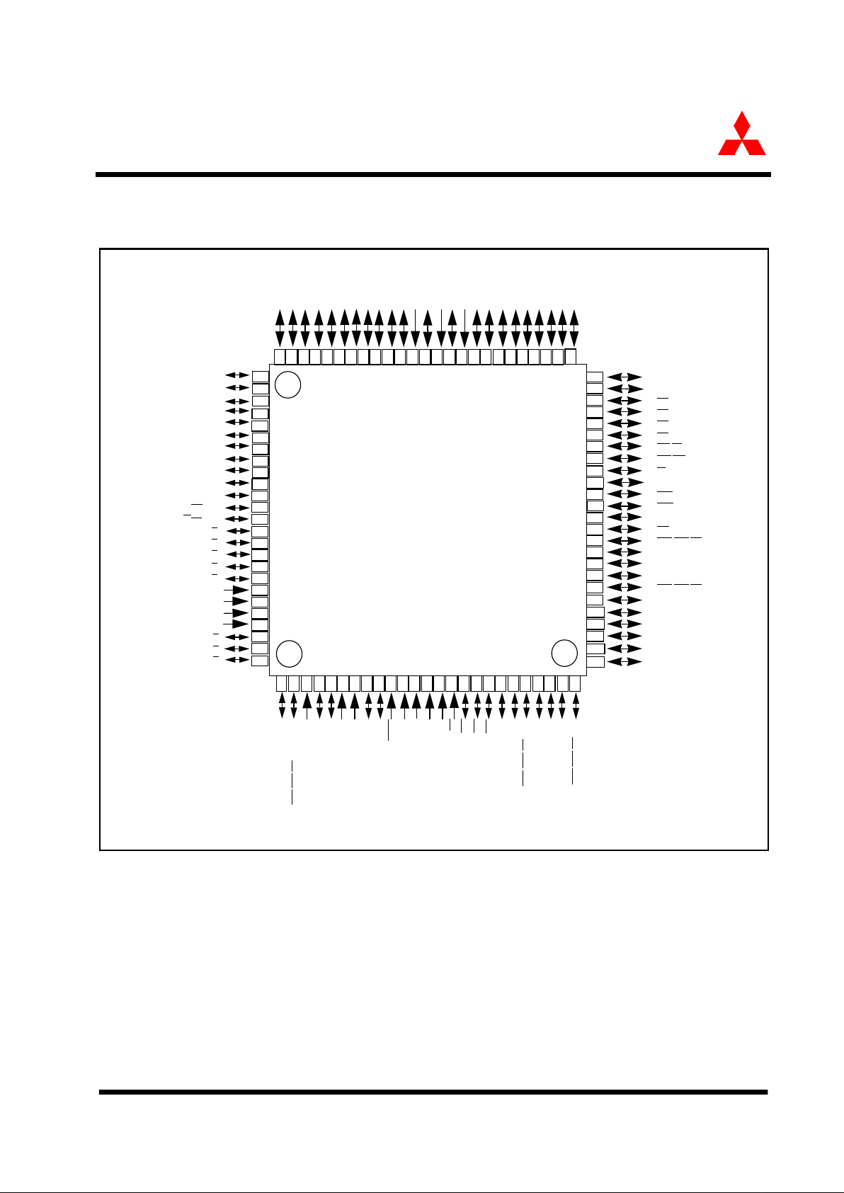
1.3 Pin Configuration
Figure 1.1 shows the pin configuration (top view).
Figure 1.1: Pin Configuration (top view)
91
85
86
87
88
89
90
92
93
94
95
96
97
98
99
81
82
83
84
100
40
P46/CS2
P05/D5
46
P03/D3
P12/D10/LED2
P02/D2
P01/D1
P00/D0
P103/
SOF/
TB1in
P101/VbusDTCT
Ext Cap
USB D+
USB D-
LPF
AVss
P47/CS3
45
P50/WRL/WR
44
P51/WRH/BHE
43
P52/RD
42
P53/BCLK
41
P54/HLDA
P55/HOLD
39
38
37
P60/CTS0/RTS0/SS0
36
P61/CLK0/SCK0
35
P62/RxD0/SCL0/STxD0/WS0
34
P63/TxD0/SDA0/SRxD0/SD0
33
P64/CTS1/RTS1/SS1
32
P66/RxD1/SCL1/STxD1/WS1
M30245Mx/FC
P42/A18
50
P43/A19
49
P44/CS0
48
P45/CS1
47
P11/D9/LED1
P10/D8/LED0
P07/D7
P06/D6
P56/ALE
P57/
RDY/CLKOUT
P04/D4
57585960616263646566676869707172737475
52
53545556
51
31
Vref
AVcc
P97/AN7
/KI7
P96/AN6
/KI6
P95/AN5
/KI5
P67/TxD1SDA1/SRxD1/SD1
P70/TxD2/SDA2/SRxD2/TA0out
P71/RxD2/SCL2/STxD2/TA0in
P72/CLK2/TA1out
P93/AN3/KI3
P92/AN2/
KI2
P91/AN1/
KI1
P90/AN0/
KI0
BYTE
CNVss
P87/XCin
P86/XCout
RESET
Xout
Vss
Xin
Vcc
P85/
NMI
P84/
INT2
P83/
INT1
P82/CLK4/INT0
P81/RxD4/SCL4/STxD4//TA4in
P80/TxD4/SDA4/SRxD4//TA4out
P77/CTS3/RTS3/SS3//TA3in
P76/CLK3/TA3out
P75/RxD3/SCL3/STxD3/TA2in
P74/TxD3/SDA3/SRxD3/TA2out
P73/
CTS2/RTS2/SS2/TA1in
2
1
2423222120191817161514131211109876543
25
30
29
28
27
26
P40/A16
P37/A15
P36/A14
P35/A13
P32/A10
P34/A12
Vcc
P31/A9
P30/A8
Vss
P27/A7
P26/A6
P25/A5
P24/A4
P23/A3
P22/;A2
P21/A1
P20/A0
P17/D15LED7
P16/D14LED6
P15/D13/LED5
P14/D12/LED4
P13/D11/LED3
P41/A17
P33/A11
80
79
78
77
76
100-pin QFP (0.5mm pitch)
P65/CLK1/SCK1
P102/AD
TRIG
/TB0in
P94/AN4/KI4
P100/CTS4/RTS4/SS4/TB2in/ATTACH
Page 3
Preliminary Specification
Specifications in this manual are tentative and subject to change
Block Diagram
1-5
Mitsubishi microcomputers
M30245 Group
SINGLE-CHIP 16-BIT CMOS MICROCOMPUTER
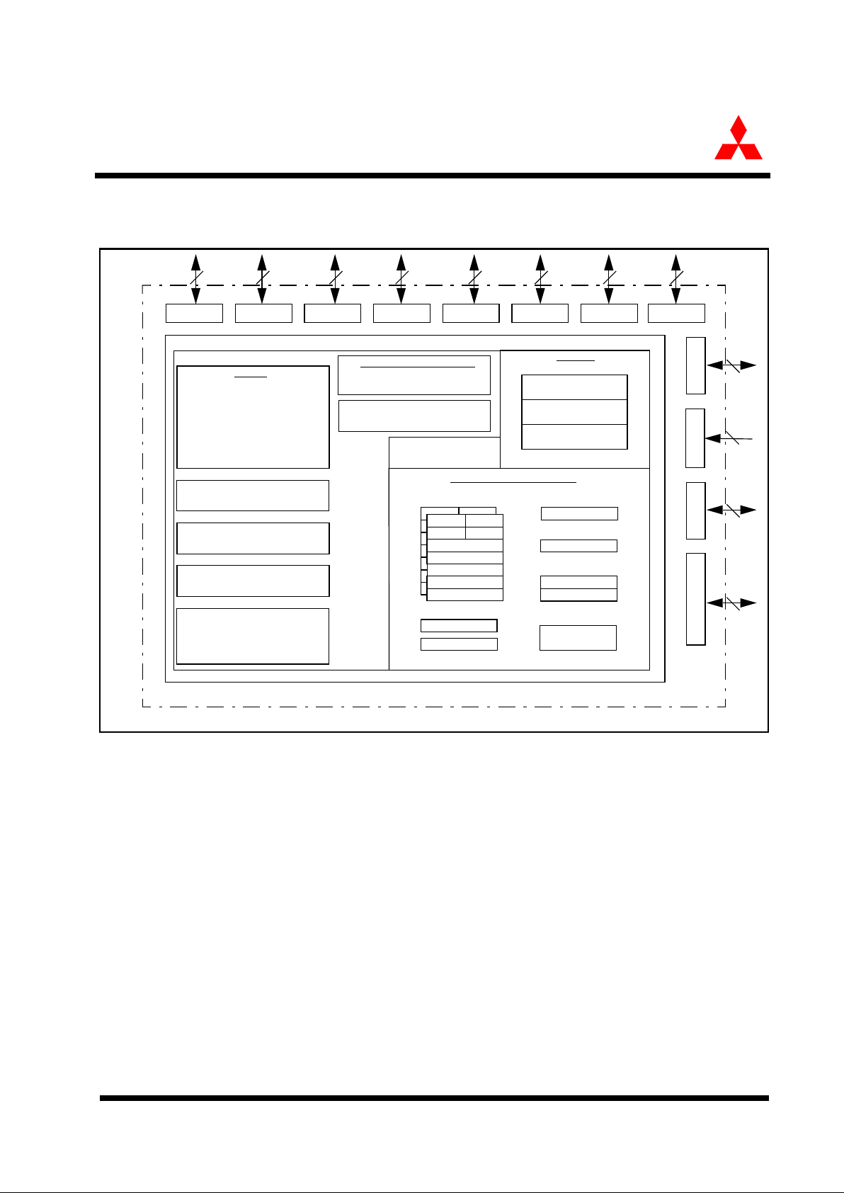
1.4 Block Diagram
Figure 1.2 is a block diagram of the M30245 group.
Figure 1.2: Block diagram of M30245 group
A1
FB
Port P0 Port P1 Port P2 Port P3 Port P4 Port P5 Port P6
Port P8 Port P9 Port P10
0
-10
3
INTB
PC
FLG
R0H R0L
R1H R1L
R2
R3
A0
A1
FB
R0H R0L
R1H R1L
R2
R3
SB
Multiplier
M16C/62 16-bit CPU Core
ROM/FLASH
RAM
Memory
CRC Arithmetic Circuit
(X16+X12+X5+1, X16+X15+X2+1)
UART/Clock Synchronous SI/O
(8 bits X 5 channels)
A-D Converter
(10 bits X 8 channels)
DMAC
(4 channels)
USB Function
(10K bytes)
USB FIFO
(3.25K bytes)
Timers
Timer TA0 (16 bits)
Timer TA1 (16 bits)
Timer TA2 (16 bits)
Timer TA3 (16 bits)
Timer TA4 (16 bits)
Timer TB0 (16 bits)
Timer TB1 (16 bits)
Timer TB2 (16 bits)
System Clock Generator
Xin - Xout
Xcin - Xcout
Watchdog Timer
(15 bits)
with frequency synthesizer
Internal Peripheral Functions
8 8 8 8 8 8 8
7 4
(128K bytes)
Port P7
8
8
A0
USP
ISP
Program counter
Vector table
Stack pointer
Registers
Port P8
5
1
Page 4
1-6
Preliminary Specification
Specifications in this manual are tentative and subject to change
Performance outline
Mitsubishi microcomputers
M30245 Group
SINGLE-CHIP 16-BIT CMOS MICROCOMPUTER
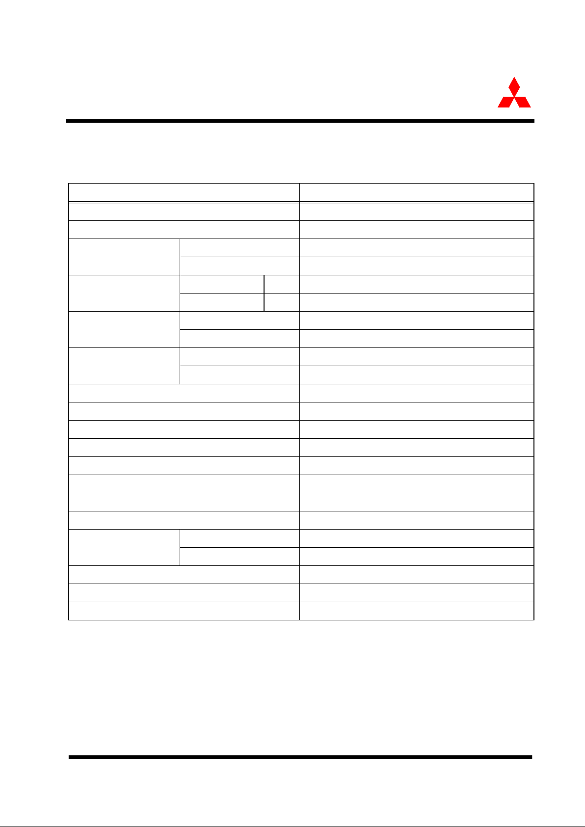
1.5 Performance outline
Table 1.1 is a performance outline of the M30245 group.
Table 1.1: Performance outline of M16C/M30245 Group
Parameters Function Description
Number of basic Instructions 91
Shortest Instruction execution time 83 ns f(Xin)= 12 MHz, Vcc = 3V
Memory size
ROM 128/64 Kbytes
RAM 10/5 Kbytes
Input/Output ports
P0~P9 I/O 8 bits x 10
P100~P101 I/O 2 bits x 1
Multifunction timer
TA0, TA1, TA2, TA3, TA4 16 bits x 5
TB0, TB1, TB2 16 bits x 3
Serial I/O
UART0~1 UART (or clock synchronous or IIS) x 2
UART2~4 UART (or clock synchronous) x 3
A-D converter 10 bits x 8 channels
DMAC 4 channels
CRC calculation circuits CRC-CCITT and CRC-16
Watchdog timer 15 bits x 1 (prescaler)
Interrupts 21 internal, 4 external sources, 4 software, 7 levels
Clock-generating circuit 2 built-in clock generating circuit
Supply voltage 3.0 ~ 3.6V, f(X
IN) = 12MHz
Power consumption TBD
I/O characteristics
I/O withstand voltage 3V
Output current 5mA (20mA available on P1, P70, P72, P74, P76, P80)
Operating temperature -20 to 85 C
Device configuration CMOS high performance silicon gate
Package 100-pin plastic mold QFP
Page 5

Preliminary Specification
Specifications in this manual are tentative and subject to change
Performance outline
1-7
Mitsubishi microcomputers
M30245 Group
SINGLE-CHIP 16-BIT CMOS MICROCOMPUTER
Mitsubishi plans to release the following products in the M30245 group:
(1) Support for Flash memory version and mask ROM versions
(2) ROM capacity: 128 or 64 Kbytes
(3) Package
• 100P6Q-A: Plastic molded QFP
Figure 1.3 shows the type number, memory size and package for the M30245 group.
Figure 1.3: Type number, memory size, and package
Table 1.2 shows the package number, type, ROM and RAM capacity for M30245 Group.
Table 1.2: M30245 Group
Type No. M30 24 X F 8 - XXX FP
Package type: GP: Package 100P6Q-A
ROM No.: Omitted for flash memory version
ROM capacity:
4: 32Kbytes
8: 64Kbytes
A: 96Kbytes
C: 128Kbytes
G: 256Kbytes
Memory type:
M: Mask ROM version
F: Flash memory version
Shows pin count, etc: The value itself has no specific meaning
M16C/M30245 Group
M16C Family
Type
ROM Capacity RAM Capacity Package Type Remarks
M30245FCGP
128K bytes 10K bytes 100P6Q-A Flash ROM Version
M30245MCGP
128K bytes 10K bytes 100P6Q-A Mask ROM Version
M30245M8GP
64K bytes 5K bytes 100P6Q-A Mask ROM Version
Page 6

1-8
Preliminary Specification
Specifications in this manual are tentative and subject to change
SFR MAP
Mitsubishi microcomputers
M30245 Group
SINGLE-CHIP 16-BIT CMOS MICROCOMPUTER
1.6 SFR MAP
The table below shows the peripheral control registers, their addresses, names, acronyms, and values
after reset.
Address
Register name
Acronym Value after reset
0000
16
0001
16
0002
16
0003
16
0004
16
Processor mode register 0 PM0
00
16
0005
16
Processor mode register 1 PM1 0 0 0
0006
16
System clock control register 0 CM0
48
16
0007
16
System clock control register 1 CM1
20
16
0008
16
Chip select control register CSR 0 0 0 0 0 0 0 1
0009
16
Address match interrupt enable register AIER 00
000A
16
Protect register PRCR 000
000B
16
Data bank register DBR 1110
000C
16
USB control register USBC
00
16
000D
16
000E
16
Watchdog timer start register WDTS
000F
16
Watchdog timer control register WDC 0 0 0 ? ? ? ? ?
0010
16
Address match interrupt register 0 RMAD0
00
16
0011
16
00
16
0012
16
0000
0013
16
0014
16
Address match interrupt register 1 RMAD1
00
16
0015
16
00
16
0016
16
0000
0017
16
0018
16
0019
16
001A
16
001B
16
001C
16
001D
16
001E
16
Reserved
001F
16
USB Attach/Detach register
00
16
0020
16
DMA0 source pointer SAR0
0021
16
0022
16
0023
16
0024
16
DMA0 destination pointer DAR0
0025
16
0026
16
0027
16
0028
16
DMA0 transfer counter TCR0
0029
16
002A
16
002B
16
002C
16
DMA0 control register DM0CON 0 0 0 0 0 ? 0 0
002D
16
002E
16
002F
16
0030
16
DMA1 source pointer SAR1
0031
16
0032
16
0033
16
0034
16
DMA1 destination pointer DAR1
0035
16
0036
16
0037
16
0038
16
DMA1 transfer counter TCR1
0039
16
003A
16
003B
16
003C
16
DMA1 control register DM1CON 0 0 0 0 0 ? 0 0
003D
16
DMA2 interrupt control register DM2IC ?000
003E
16
DMA3 interrupt control register DM3IC ?000
003F
16
USB function interrupt control register USBFIC ?000
Page 7

Preliminary Specification
Specifications in this manual are tentative and subject to change
SFR MAP
1-9
Mitsubishi microcomputers
M30245 Group
SINGLE-CHIP 16-BIT CMOS MICROCOMPUTER
0040
16
USB SOF interrupt control register SOFIC ?000
0041
16
Suspend interrupt control register SUSPIC ?000
0042
16
Reset interrupt control register RSTIC ?000
0043
16
Resume interrupt control register RSMIC ?000
0044
16
UART0/1Bus collisioninterruptcontrolregister
S01BCNIC ?000
0045
16
UART2 Bus collision interrupt control register
S2BCNIC ?000
0046
16
UART4 transmit interrupt control register S4TIC ?000
0047
16
UART4 receive interrupt control register S4RIC ?000
0048
16
UART3 transmit interrupt control register S3TIC ?000
0049
16
UART3 receive interrupt control register S3RIC ?000
004A
16
UART3/4Bus collisioninterruptcontrolregister
S34BCNIC ?000
004B
16
DMA0 interrupt control register DM0IC ?000
004C
16
DMA1 interrupt conrol register DM1IC ?000
004D
16
Key input interrupt control register KUPIC ?000
004E
16
A-D conversion interrupt control register ADIC ?000
004F
16
UART2 transmit interrupt control register S2TIC ?000
0050
16
UART2 receive interrupt control register S2RIC ?000
0051
16
UART0 transmit interrupt control register S0TIC ?000
0052
16
UART0 receive interrupt control register S0RIC ?000
0053
16
UART1 transmit interrupt control register S1TIC ?000
0054
16
UART1 receive interrupt control register S1RIC ?000
0055
16
TIMER A0 interrupt control register TA0IC ?000
0056
16
TIMER A1 interrupt control register TA1IC ?000
0057
16
TIMER A2 interrupt control register TA2IC ?000
0058
16
TIMER A3 interrupt control register TA3IC ?000
0059
16
TIMER A4 interrupt control register TA4IC ?000
005A
16
TIMER B0 interrupt control register TB0IC ?000
005B
16
TIMER B1 interrupt control register TB1IC ?000
005C
16
TIMER B2 interrupt control register TB2IC ?000
005D
16
INT0 interrupt control register INT0IC 00?000
005E
16
INT1 interrupt control register INT1IC 00?000
005F
16
INT2 interrupt control register INT2IC 00?000
0060
16
DMA2 source pointer SAR2
0061
16
0062
16
0063
16
0064
16
DMA2 destination pointer DAR2
0065
16
0066
16
0067
16
0068
16
DMA2 transfer counter TCR2
0069
16
006A
16
006B
16
006C
16
DMA2 control register DM2CON 0 0 0 0 0 ? 0 0
006D
16
006E
16
006F
16
0070
16
DMA3 source pointer SAR3
0071
16
0072
16
0073
16
0074
16
DMA3 destination pointer DAR3
0075
16
0076
16
0077
16
0078
16
DMA3 transfer counter TCR3
0079
16
007A
16
007B
16
007C
16
DMA3 control register DM3CON 0 0 0 0 0 ? 0 0
007D
16
007E
16
007F
16
Address
Register name
Acronym Value after reset
Page 8

1-10
Preliminary Specification
Specifications in this manual are tentative and subject to change
SFR MAP
Mitsubishi microcomputers
M30245 Group
SINGLE-CHIP 16-BIT CMOS MICROCOMPUTER
- - -
0280
16
USB address register USBA
00
16
0281
16
0282
16
USB poer management register USBPM
00
16
0283
16
0284
16
USB interrupt status register 1 USBIS0
00
16
0285
16
0286
16
USB interrupt status register 1 USBIS1
00
16
0287
16
0288
16
USB interrupt enable register USBER
33FF
16
0289
16
028A
16
USB frame number register low USBSOF
0000
16
028B
16
028C
16
USB ISO control register USBISOC 0 0
028D
16
028E
16
USB endpoint enable USBEPEN ?000
028F
16
0290
16
USB DMA0 source register USBSAR0
00
16
0291
16
0292
16
USB DMA1 source register USBSAR1
00
16
0293
16
0294
16
USB DMA2 source register USBSAR2
00
16
0295
16
0296
16
USB DMA3 source register USBSAR3
00
16
0297
16
0298
16
USB EP0 control/status register
00
16
0299
16
029A
16
USB EP0 max packet size register
08
16
029B
16
029C
16
USB EP0 write count register
00
16
029D
16
029E
16
USB EP1 IN control/status register
00
16
029F
16
02A0
16
USB EP1 IN max packet size register
00
16
02A1
16
02A2
16
USB EP1 IN FIFO configuration register
02A3
16
02A4
16
USB EP2 IN control/status register
00
16
02A5
16
02A6
16
USB EP2 IN max packet size register
00
16
02A7
16
02A8
16
USB EP2 IN FIFO configuration register
02A9
16
02AA
16
USB EP3 IN control/status register
00
16
02AB
16
02AC
16
USB EP3 IN max packet size register
00
16
02AD
16
02AE
16
USB EP3 IN FIFO configuration register
02AF
16
02B0
16
USB EP4 IN control/status register
00
16
02B1
16
02B2
16
USB EP4 IN max packet size register
00
16
02B3
16
02B4
16
USB EP4 IN FIFO configuration register
02B5
16
02B6
16
USB EP1 OUT control/status register
00
16
02B7
16
02B8
16
USB EP1 OUT max packet size register
00
16
02B9
16
02BA
16
USB EP1 OUT write count register
00
16
02BB
16
02BC
16
USB EP1 OUT FIFO configuration register
00
16
02BD
16
02BE
16
USB reserved
02BF
16
USB reserved
Address
Register name
Acronym Value after reset
Page 9

Preliminary Specification
Specifications in this manual are tentative and subject to change
SFR MAP
1-11
Mitsubishi microcomputers
M30245 Group
SINGLE-CHIP 16-BIT CMOS MICROCOMPUTER
02C0
16
USB EP2 OUT control/status register
00
16
02C1
16
02C2
16
USB EP2 OUT max packet size register
00
16
02C3
16
02C4
16
USB EP2 OUT write count register
00
16
02C5
16
02C6
16
USB EP2 OUT FIFO configuration register
02C7
16
02C8
16
USB EP3 OUT control/status register
00
16
02C9
16
02CA
16
USB EP3 OUT max packet size register
00
16
02CB
16
02CC
16
USB EP3 OUT write count register
00
16
02CD
16
02CE
16
USB EP3 OUT FIFO configuration register
02CF
16
02D0
16
USB EP4 OUT control/status register
00
16
02D1
16
02D2
16
USB EP4 OUT max packet size register
00
16
02D3
16
02D4
16
USB EP4 OUT write count register
00
16
02D5
16
02D6
16
USB EP4 OUT FIFO configuration register
02D7
16
02D8
16
USB reserved
02D9
16
USB reserved
02DA
16
USB reserved
02DB
16
USB reserved
02DC
16
USB reserved
02DD
16
USB reserved
02DE
16
USB reserved
02DF
16
USB reserved
02E0
16
USB EP0 IN FIFO
02E1
16
02E2
16
USB EP0 OUT FIFO
02E3
16
02E4
16
USB EP1 IN FIFO
02E5
16
02E6
16
USB EP1 OUT FIFO
02E7
16
02E8
16
USB EP2 IN FIFO
02E9
16
02EA
16
USB EP2 OUT FIFO
02EB
16
02EC
16
USB EP3 IN FIFO
02ED
16
02EE
16
USB EP3 OUT FIFO
02EF
16
02F0
16
USB EP4 IN FIFO
02F1
16
02F2
16
USB EP4 OUT FIFO
02F3
16
02F4
16
02F5
16
02F6
16
02F7
16
02F8
16
02F9
16
02FA
16
02FB
16
02FC
16
02FD
16
02FE
16
02FF
16
Address
Register name
Acronym Value after reset
Page 10

1-12
Preliminary Specification
Specifications in this manual are tentative and subject to change
SFR MAP
Mitsubishi microcomputers
M30245 Group
SINGLE-CHIP 16-BIT CMOS MICROCOMPUTER
0300
16
0301
16
0302
16
0303
16
0304
16
0305
16
0306
16
0307
16
0308
16
0309
16
030A
16
030B
16
030C
16
030D
16
030E
16
030F
16
0310
16
0311
16
0312
16
0313
16
0314
16
UART4 special mode register 4 U4SMR4
00
16
0315
16
UART4 special mode register 3 U4SMR3
00
16
0316
16
UART4 special mode register 2 U4SMR2
00
16
0317
16
UART4 special mode register U4SMR
00
16
0318
16
UART4 transmit / receive mode register U4MR
00
16
0319
16
UART4 bit rate generator U4BRG
031A
16
UART4 transmit buffer register U4TB
031B
16
031C
16
UART4transmit/ receive control register 0 U4C0
08
16
031D
16
UART4transmit/ receive control register 1 U4C1
02
16
031E
16
UART4 receive buffer register U4RB
031F
16
0320
16
0321
16
0322
16
0323
16
0324
16
UART3 special mode register 4 U3SMR4
00
16
0325
16
UART3 special mode register 3 U3SMR3
00
16
0326
16
UART3 special mode register 2 U3SMR2
00
16
0327
16
UART3 special mode register U3SMR
00
16
0328
16
UART3 transmit / receive mode register U3MR
00
16
0329
16
UART3 bit rate generator U3BRG
032A
16
UART3 transmit buffer register U3TB
032B
16
032C
16
UART3transmit/ receive control register 0 U3C0
08
16
032D
16
UART3transmit/ receive control register 1 U3C1
02
16
032E
16
UART3 receive buffer register U3RB
032F
16
0330
16
0331
16
0332
16
0333
16
0334
16
UART2 special mode register 4 U2SMR4
00
16
0335
16
UART2 special mode register 3 U2SMR3
00
16
0336
16
UART2 special mode register 2 U2SMR2
00
16
0337
16
UART2 special mode register U2SMR
00
16
0338
16
UART2 transmit / receive mode register U2MR
00
16
0339
16
UART2 bit rate generator U2BRG
033A
16
UART2 transmit buffer register U2TB
033B
16
033C
16
UART2transmit/ receive control register 0 U2C0
08
16
033D
16
UART2transmit/ receive control register 1 U2C1
02
16
033E
16
UART2 receive buffer register U2RB
033F
16
Address
Register name
Acronym Value after reset
Page 11

Preliminary Specification
Specifications in this manual are tentative and subject to change
SFR MAP
1-13
Mitsubishi microcomputers
M30245 Group
SINGLE-CHIP 16-BIT CMOS MICROCOMPUTER
0340
16
0341
16
0342
16
Timer A1-1 register TA11
0343
16
0344
16
Timer A1-2 register TA12
0345
16
0346
16
Timer A1-3 register TA13
0347
16
0348
16
Three-phase PWM control register 0 INVC0
00
16
0349
16
Three-phase PWM control register 1 INVC1 0 0 0 0 ? 0 0 0
034A
16
Three-phase output buffer register 0 IDB0
00
16
034B
16
Three-phase output buffer register 1 IDB1
00
16
034C
16
Dead time timer DTT
034D
16
Timer B2 interrupt occurance frequency set counter
ICTB2
034E
16
034F
16
0350
16
0351
16
0352
16
0353
16
0354
16
0355
16
0356
16
0357
16
0358
16
0359
16
035A
16
035B
16
035C
16
035D
16
035E
16
035F
16
Interrupt cause select register IFSR
00
16
0360
16
0361
16
0362
16
0363
16
0364
16
UART1 special mode register 4 U1SMR4
00
16
0365
16
UART1 special mode register 3 U1SMR3
00
16
0366
16
UART1 special mode register 2 U1SMR2
00
16
0367
16
UART1 special mode register U1SMR
00
16
0368
16
UART1 transmit / receive mode register U1MR
00
16
0369
16
UART1 bit rate generator U1BRG
036A
16
UART1 transmit buffer register U1TB
036B
16
036C
16
UART1transmit/ receive control register 0 U1C0
08
16
036D
16
UART1transmit/ receive control register 1 U1C1
02
16
036E
16
UART1 receive buffer register U1RB
036F
16
0370
16
0371
16
0372
16
0373
16
0374
16
0375
16
0376
16
0377
16
0378
16
0379
16
037A
16
037B
16
037C
16
037D
16
037E
16
037F
16
Address
Register name
Acronym Value after reset
Page 12

1-14
Preliminary Specification
Specifications in this manual are tentative and subject to change
SFR MAP
Mitsubishi microcomputers
M30245 Group
SINGLE-CHIP 16-BIT CMOS MICROCOMPUTER
0380
16
Count start flag TABSR
00
16
0381
16
Clock prescaler reset flag CPSRF 0
0382
16
One-shot start flag ONSF 0 0 00000
0383
16
Trigger select register TRGSR
00
16
0384
16
Up-down flag UDF
00
16
0385
16
0386
16
Timer A0 TA0
0387
16
0388
16
Timer A1 TA1
0389
16
038A
16
Timer A2 TA2
038B
16
038C
16
Timer A3 TA3
038D
16
038E
16
Timer A4 TA4
038F
16
0390
16
Timer B0 TB0
0391
16
0392
16
Timer B1 TB1
0393
16
0394
16
Timer B2 TB2
0395
16
0396
16
Timer A0 mode register TA0MR
00
16
0397
16
Timer A1 mode register TA1MR
00
16
0398
16
Timer A2 mode register TA2MR
00
16
0399
16
Timer A3 mode register TA3MR
00
16
039A
16
Timer A4 mode register TA4MR
00
16
039B
16
Timer B0 mode register TB0MR 0 0 ? 0000
039C
16
Timer B1 mode register TB1MR 0 0 ? 0000
039D
16
Timer B2 mode register TB2MR 0 0 ? 0000
039E
16
Timer B2 special mode register TB2SC 0
039F
16
Timer count source prescaler TCSPR 0 ????
03A0
16
03A1
16
03A2
16
03A3
16
03A4
16
UART0 special mode register 4 U0SMR4
00
16
03A5
16
UART0 special mode register 3 U0SMR3
00
16
03A6
16
UART0 special mode register 2 U0SMR2
00
16
03A7
16
UART0 special mode register U0SMR
00
16
03A8
16
UART0 transmit / receive mode register U0MR
00
16
03A9
16
UART0 bit rate generator U0BRG
03AA
16
UART0 transmit buffer register U0TB
03AB
16
03AC
16
UART0transmit/ receive control register 0 U0C0
08
16
03AD
16
UART0transmit/ receive control register 1 U0C1
02
16
03AE
16
UART0 receive buffer register U0RB
03AF
16
03B0
16
DMA2 cause select register DM2SL
00
16
03B1
16
03B2
16
DMA3 cause select register DM3SL
00
16
03B3
16
03B4
16
03B5
16
03B6
16
03B7
16
03B8
16
DMA0 cause select register DM0SL
00
16
03B9
16
03BA
16
DMA1 cause select register DM1SL
00
16
03BB
16
CRC mode register CRCMR 0 0
03BC
16
CRC data register CRCD
03BD
16
03BE
16
CRC input register CRCIN
03BF
16
Address
Register name
Acronym Value after reset
Page 13

Preliminary Specification
Specifications in this manual are tentative and subject to change
SFR MAP
1-15
Mitsubishi microcomputers
M30245 Group
SINGLE-CHIP 16-BIT CMOS MICROCOMPUTER
03C0
16
A-D register 0 AD0
03C1
16
03C2
16
A-D register 1 AD1
03C3
16
03C4
16
A-D register 2 AD2
03C5
16
03C6
16
A-D register 3 AD3
03C7
16
03C8
16
A-D register 4 AD4
03C9
16
03CA
16
A-D register 5 AD5
03CB
16
03CC
16
A-D register 6 AD6
03CD
16
03CE
16
A-D register 7 AD7
03CF
16
03D0
16
03D1
16
03D2
16
03D3
16
03D4
16
A-D control register 2 ADCON2 0
03D5
16
03D6
16
A-D control register 0 ADCON0 0 0 0 0 0 ? ? ?
03D7
16
A-D conrol register 1 ADCON1
00
16
03D8
16
03D9
16
03DA
16
03DB
16
Frequency synthesizer clock control FSCCR
00
16
03DC
16
Frequency synthesizer control FSC
60
16
03DD
16
Frequency synthesizer multiplier control FSM
FF
16
03DE
16
Frequency synthesizer prescaler control FSP
FF
16
03DF
16
Frequency synthesizer divider FSD
FF
16
03E0
16
Port P0 P0
03E1
16
Port P1 P1
03E2
16
Port P0 direction register PD0
00
16
03E3
16
Port P1 direction register PD1
00
16
03E4
16
Port P2 P2
03E5
16
Port P3 P3
03E6
16
Port P2 direction register PD2
00
16
03E7
16
Port P3 direction register PD3
00
16
03E8
16
03E9
16
03EA
16
03EB
16
03EC
16
Port P6 P6
03ED
16
Port P7 P7
03EE
16
Port P6 direction register PD6
00
16
03EF
16
Port P7 direction register PD7
00
16
03F0
16
Port P8 P8
03F1
16
03F2
16
Port P8 direction register PD8
00
16
03F3
16
03F4
16
Port P10 P10
03F5
16
03F6
16
Port P10 direction register PD10
00
16
03F7
16
03F8
16
03F9
16
03FA
16
P2 drive capacity P2DR
03FB
16
PWM drive capacity PWMDR
03FC
16
Pull-up control register 0 PUR0
00
16
03FD
16
Pull-up control register 1 PUR1
00
16
03FE
16
03FF
16
Address
Register name
Acronym Value after reset
 Loading...