

Page 1
查询M27W512-100B6TR供应商查询M27W512-100B6TR供应商
M27W512
512 Kbit (64Kb x8) Low Voltage UV EPROM and OTP EPROM
■ 2.7V to 3.6V SUPPLY VOLTAGE in READ
OPERATION
■ ACCESS TIME:
–70nsatVCC= 3.0V to 3.6V
–80nsatVCC= 2.7V to 3.6V
■ PIN COMPATIBLE with M27C512
■ LOW POWER CONSUMPTION:
–15µA max Standby Current
– 15mA max Active Current at 5MHz
■ PROGRAMMING TIME 100
■ HIGH RELIABILITY CMOS TECHNOLOGY
s/byte
µ
– 2,000V ESD Protection
– 200mA Latchup Protection Immunity
■ ELECTRONIC SIGNATURE
– Manufacturer Code: 20h
– Device Code: 3Dh
DESCRIPTION
The M27W512 is a low voltage 512 Kbit EPROM
offered in the two range UV (ultraviolet erase)and
OTP (one time programmable). It is ideally suited
for microprocessor systems and is organized as
65,536 by 8bits.
The M27W512 operates in the read mode with a
supply voltageas low as 2.7V at –40 to 85°C temperature range. The decrease in operating power
allows either a reduction of the size of the battery
or an increase in the time between battery recharges.
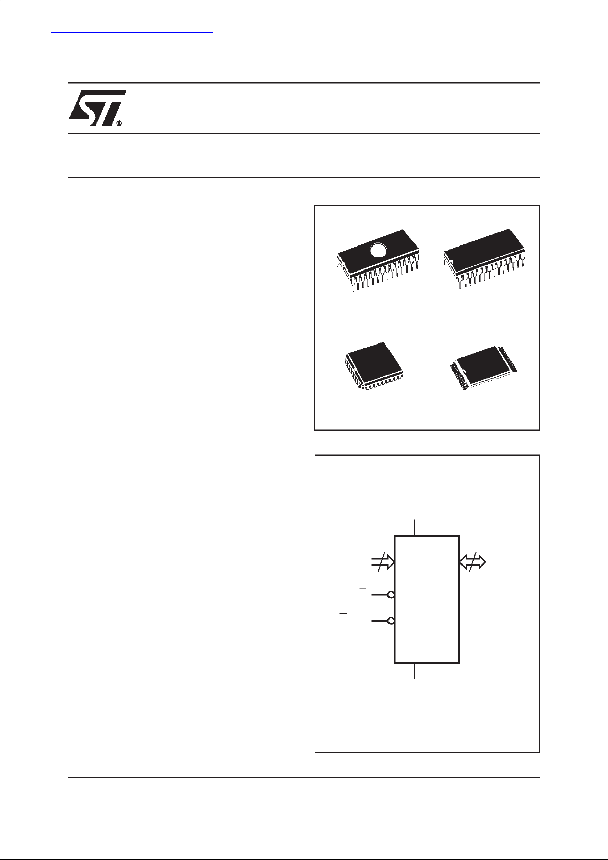
The FDIP28W (window ceramic frit-seal package)
has transparent lid which allows the user to expose the chipto ultraviolet lighttoerase the bit pattern. A new pattern can then be written to the
device by following the programming procedure.
For applications wherethe content is programmed
only one time and erasure is not required, the
M27W512 is offered in PDIP28, PLCC32 and
TSOP28 (8 x 13.4 mm) packages.
28
1
FDIP28W (F) PDIP28 (B)
PLCC32 (K) TSOP28 (N)
Figure 1. Logic Diagram
16
A0-A15
E
GV
PP
28
V
CC
M27W512
V
SS
1
8 x 13.4 mm
8
Q0-Q7
AI01584
1/16March 2000
Page 2
M27W512
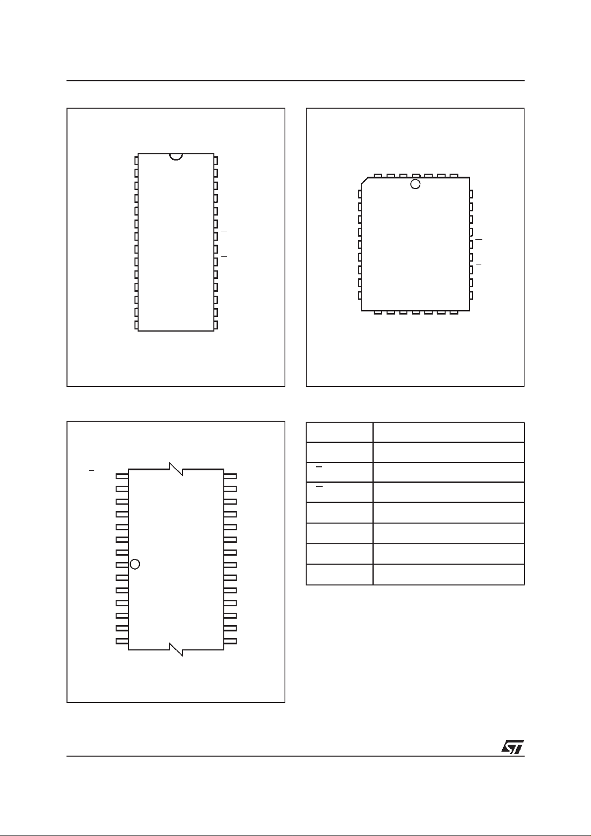
Figure 2A. DIP Connections
A15 V
1
A12
2
A7
3
A6
4
A5
5
A4
6
A3
7
A2
A1
A0
Q0
Q2
SS
M27W512
8
9
10
11
12
13
14
28
27
26
25
24
23
22
21
20
19
18
17
16
15
AI02679
CC
A14
A13
A8
A9
A11
GV
A10
E
Q7
Q6
Q5Q1
Q4
Q3V
PP
Figure 2B. LCC Connections
A15
A6
A5
A4
A3
A2
A1
A0
NC
Q0
A7
9
Q1
DU
A12
1
32
M27W512
17
Q2
SS
DU
V
V
Q3
CC
A14
Q4
A13
25
Q5
A8
A9
A11
NC
GV
A10
E
Q7
Q6
AI01585
PP
Figure 2C. TSOP Connections
GV
A11
A13
A14
V
A15
A12
PP
A9
A8
CC
A7
A6
A5
A4
A3
22
28
M27W512
1
78
21
15
14
AI01586
A10
E
Q7
Q6
Q5
Q4
Q3
V
SS
Q2
Q1
Q0
A0
A1
A2
Table 1. Signal Names
A0-A15 Address Inputs
Q0-Q7 Data Outputs
E Chip Enable
GV
V
V
NC
DU
PP
CC
SS
Output Enable / Program Supply
Supply Voltage
Ground
Not Connected Internally
Don’t Use
2/16
Page 3
M27W512
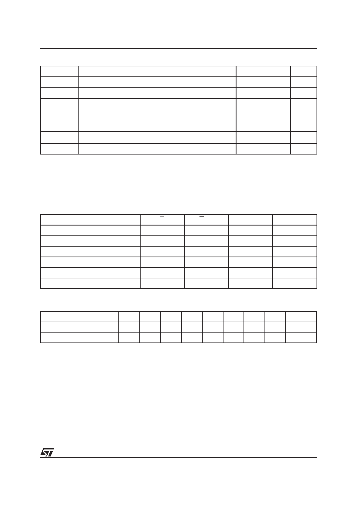
Table 2. Absolute Maximum Ratings
(1)
Symbol Parameter Value Unit
T
A
T
BIAS
T
STG
(2)
V
IO
V
CC
(2)
V
A9
V
PP
Note: 1. Except for the rating ”Operating Temperature Range”, stresses above those listed in the Table ”Absolute Maximum Ratings” may
cause permanent damage to the device. These are stress ratings only and operation of thedevice at these or anyother conditions
above those indicated in the Operating sections of this specification is not implied. Exposure to Absolute Maximum Rating conditions for extended periods may affect device reliability. Refer also to the STMicroelectronics SURE Program andother relevant quality documents.
2. Minimum DC voltage on Input or Output is –0.5V with possible undershoot to –2.0V for a period less than 20ns. Maximum DC
voltage on Output is V
3. Depends on range.
Ambient Operating Temperature
Temperature Under Bias –50 to 125 °C
Storage Temperature –65 to 150 °C
Input or Output Voltage (except A9) –2 to 7 V
Supply Voltage –2 to 7 V
A9 Voltage –2 to 13.5 V
Program Supply Voltage –2 to 14 V
+0.5V with possible overshoot to VCC+2V for a period less than 20ns.
CC
(3)
–40 to 125 °C
Table 3. Operating Modes
Mode E
Read
Output Disable V
Program
V
Program Inhibit V
Standby
Electronic Signature
Note: X = VIHor VIL,VID= 12V ± 0.5V.
V
IL
IL
Pulse V
IL
IH
V
IH
V
IL
GV
V
PP
V
IL
V
IH
PP
PP
A9 Q7-Q0
X Data Out
X Hi-Z
XDataIn
X Hi-Z
X X Hi-Z
V
IL
V
ID
Codes
Table 4. Electronic Signature
Identifier A0 Q7 Q6 Q5 Q4 Q3 Q2 Q1 Q0 Hex Data
Manufacturer’s Code
Device Code
V
IL
V
IH
00100000 20h
00111101 3Dh
3/16
Page 4
M27W512
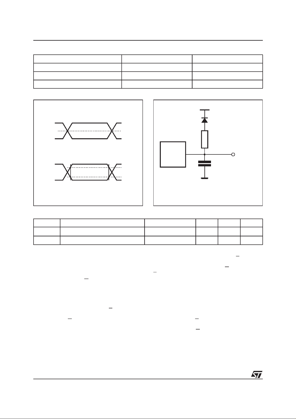
Table 5. AC Measurement Conditions
High Speed Standard
Input Rise and Fall Times ≤ 10ns ≤ 20ns
Input Pulse Voltages 0 to 3V 0.4V to 2.4V
Input and Output Timing Ref. Voltages 1.5V 0.8V and 2V
Figure 3. AC Testing Input Output Waveform
High Speed
3V
1.5V
0V
Standard
2.4V
0.4V
Table 6. Capacitance
Symbol Parameter Test Condition Min Max Unit
C
IN
C
OUT
Note: 1. Sampled only, not 100% tested.
Input Capacitance
Output Capacitance
(1)
(TA=25°C, f = 1 MHz)
2.0V
0.8V
AI01822
Figure 4. AC Testing Load Circuit
1.3V
1N914
3.3kΩ
DEVICE
UNDER
TEST
C
L
CL= 30pF for High Speed
CL= 100pF for Standard
CLincludes JIG capacitance
V
V
IN
OUT
=0V
=0V
6pF
12 pF
OUT
AI01823B
DEVICE OPERATION
The modes of operationsof the M27W512 are listed in the Operating Modes table. A single power
supply is required in the read mode. All inputs are
TTL levels except for GVPPand 12V on A9 for
Electronic Signature.
Read Mode
The M27W512 has two control functions, both of
which must be logically active in order to obtain
data at the outputs. Chip Enable (E) is the power
control and should be used for device selection.
Output Enable(G) is the output control and should
be used to gate data to the output pins, independent of device selection. Assuming that the addresses are stable, the address access time
4/16
(t
) is equal to the delay from E to output
AVQV
(t
). Data is available at the output aftera delay
ELQV
of t
from the falling edge of G, assuming that
GLQV
E has been low and the addresses have been stable for at least t
AVQV-tGLQV
.
Standby Mode
The M27W512 has a standby mode which reduces the supply current from 15mA to 15µA with low
voltage operation VCC≤ 3.6V, see Read ModeDC
Characteristics table for details. The M27W512 is
placed in the standby mode by applying a CMOS
high signal to the E input. When in the standby
mode, the outputs are in a high impedance state,
independent of the GVPPinput.
Page 5
M27W512
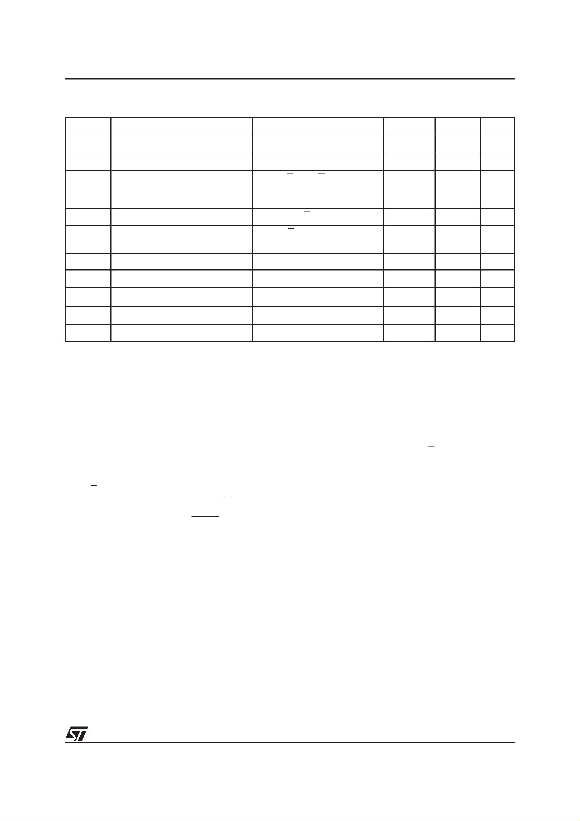
Table 7. Read Mode DC Characteristics
(1)
(TA= –40 to 85°C; VCC= 2.7V to 3.6V; VPP=VCC)
Symbol Parameter Test Condition Min Max Unit
I
I
I
CC
I
CC1
I
CC2
I
V
V
IH
V
V
Note: 1. VCCmust be applied simultaneously with or before VPPand removed simultaneously or after VPP.
Two Line Output Control
Because EPROMs are usually used in larger
memory arrays, the product features a 2 line control function which accommodates the use of multiple memory connection. The two line control
function allows:
a. the lowest possible memory power dissipation,
b. complete assurance that output bus contention
will not occur.
For the most efficient use of these two control
lines, Eshould be decoded and used as the primary device selecting function, while G should be
made a common connection to all devices in the
array and connected to the READ line from the
system controlbus. This ensures that all deselected memory devicesare in their low power standby
mode and that the output pins are only active
when data is required from a particular memory
device.
Input Leakage Current
LI
Output Leakage Current
LO
Supply Current
Supply Current (Standby) TTL
Supply Current (Standby) CMOS
Program Current
PP
Input Low Voltage –0.6
IL
(2)
Input High Voltage
Output Low Voltage
OL
Output High Voltage TTL
OH
2. Maximum DC voltage on Output is V
CC
+0.5V.
I
OUT
0V ≤ V
0V ≤ V
E=V
E>V
≤ V
IN
CC
≤ V
OUT
IL
= 0mA, f = 5MHz
V
CC
E=V
CC
V
CC
V
PP=VCC
I
= 2.1mA
OL
I
= –1mA
OH
CC
,G=VIL,
≤ 3.6V
IH
– 0.2V,
≤ 3.6V
System Considerations
The power switching characteristics of Advanced
CMOS EPROMs require careful decoupling of the
devices. The supply current, ICC, has three segments that are of interest to the system designer:
the standby current level, the active current level,
and transient current peaks that are produced by
the falling and rising edges of E. The magnitude of
the transient current peaks is dependent on the
capacitive and inductive loading of the device at
the output.
The associated transient voltage peaks can be
suppressed by complying with the two line output
control and by properly selected decoupling capacitors. It is recommended that a 0.1µF ceramic
capacitor be used on every device between V
and VSS. This should be a high frequency capacitor of low inherent inductance and should be
placed as close to the device as possible. In addition, a 4.7µF bulk electrolytic capacitor should be
±10 µA
±10 µA
15 mA
1mA
15 µA
10 µA
0.2 V
CC
0.7 V
2.4 V
CC
VCC+ 0.5
0.4 V
used between VCCand VSSfor every eight devices. The bulkcapacitor should be located near the
power supply connection point.Thepurpose of the
bulk capacitor is to overcome the voltage drop
caused by the inductive effects of PCB traces.
V
V
CC
5/16
Page 6
M27W512
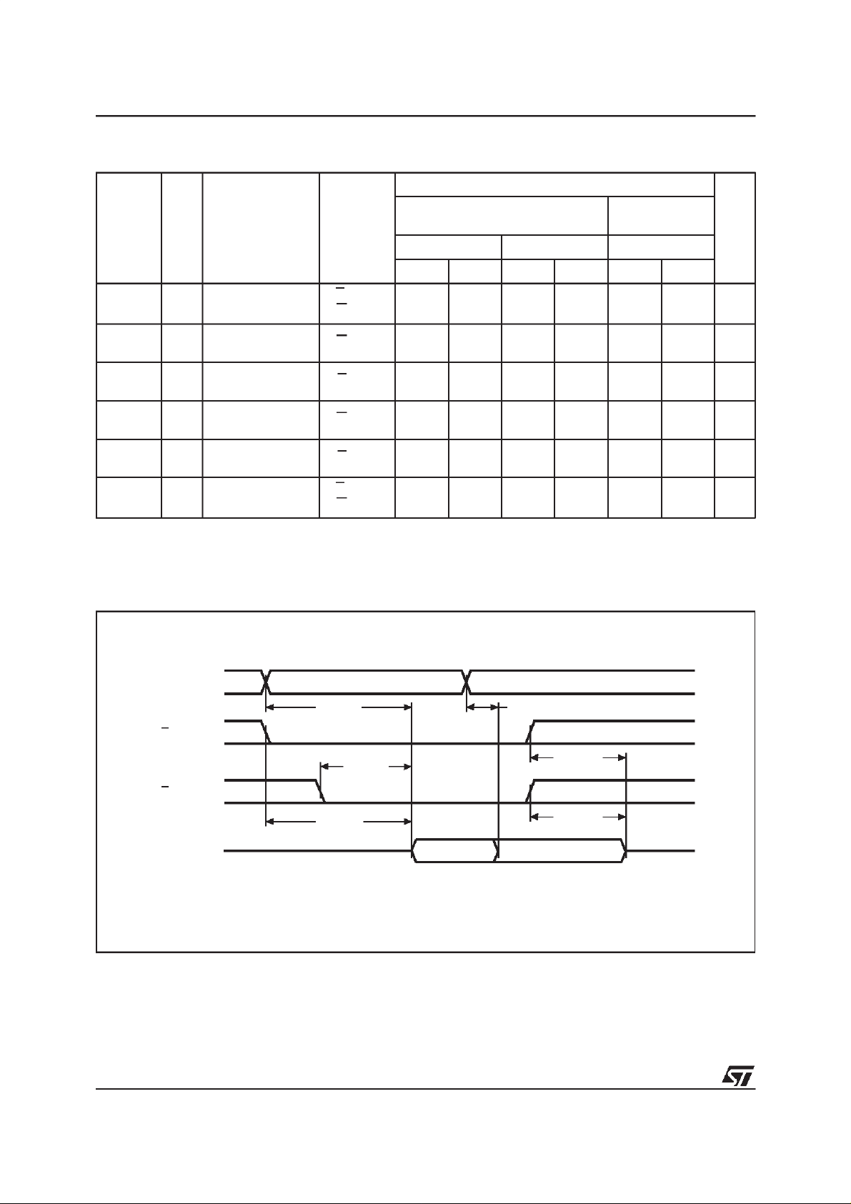
Table 8. Read Mode AC Characteristics
(1)
(TA= –40 to 85°C; VCC= 2.7V to 3.6V; VPP=VCC)
M27W102
(3)
Symbol Alt Parameter
Test
Condition
VCC= 3.0V to 3.6V VCC= 2.7V to 3.6V VCC= 2.7V to 3.6V
Min Max Min Max Min Max
E=V
G=V
G=V
E=V
G=V
E=V
E=V
G=V
,
IL
IL
IL
IL
IL
IL
,
IL
IL
0 40 0 50 0 60 ns
0 40 0 50 0 60 ns
000ns
t
AVQV
t
ELQV
t
GLQV
(2)
t
EHQZ
(2)
t
GHQZ
t
AXQX
Note: 1. VCCmust be applied simultaneously with or before VPPand removed simultaneously or after VPP.
2. Sampled only, not 100% tested.
3. Speed obtained with High Speed AC measurement conditions.
Address Valid to
t
ACC
Output Valid
Chip Enable Low to
t
CE
Output Valid
Output Enable Low
t
OE
to Output Valid
Chip Enable High
t
DF
to Output Hi-Z
Output EnableHigh
t
DF
to Output Hi-Z
Address Transition
t
OH
to Output Transition
-80
70 80 100 ns
70 80 100 ns
40 50 60 ns
-100
(-120/-150/-200)
Unit
Figure 5. Read Mode AC Waveforms
A0-A15
tAVQV
E
G
tELQV
Q0-Q7
VALID
tGLQV
VALID
tAXQX
tEHQZ
tGHQZ
Hi-Z
AI00735B
6/16
Page 7
M27W512
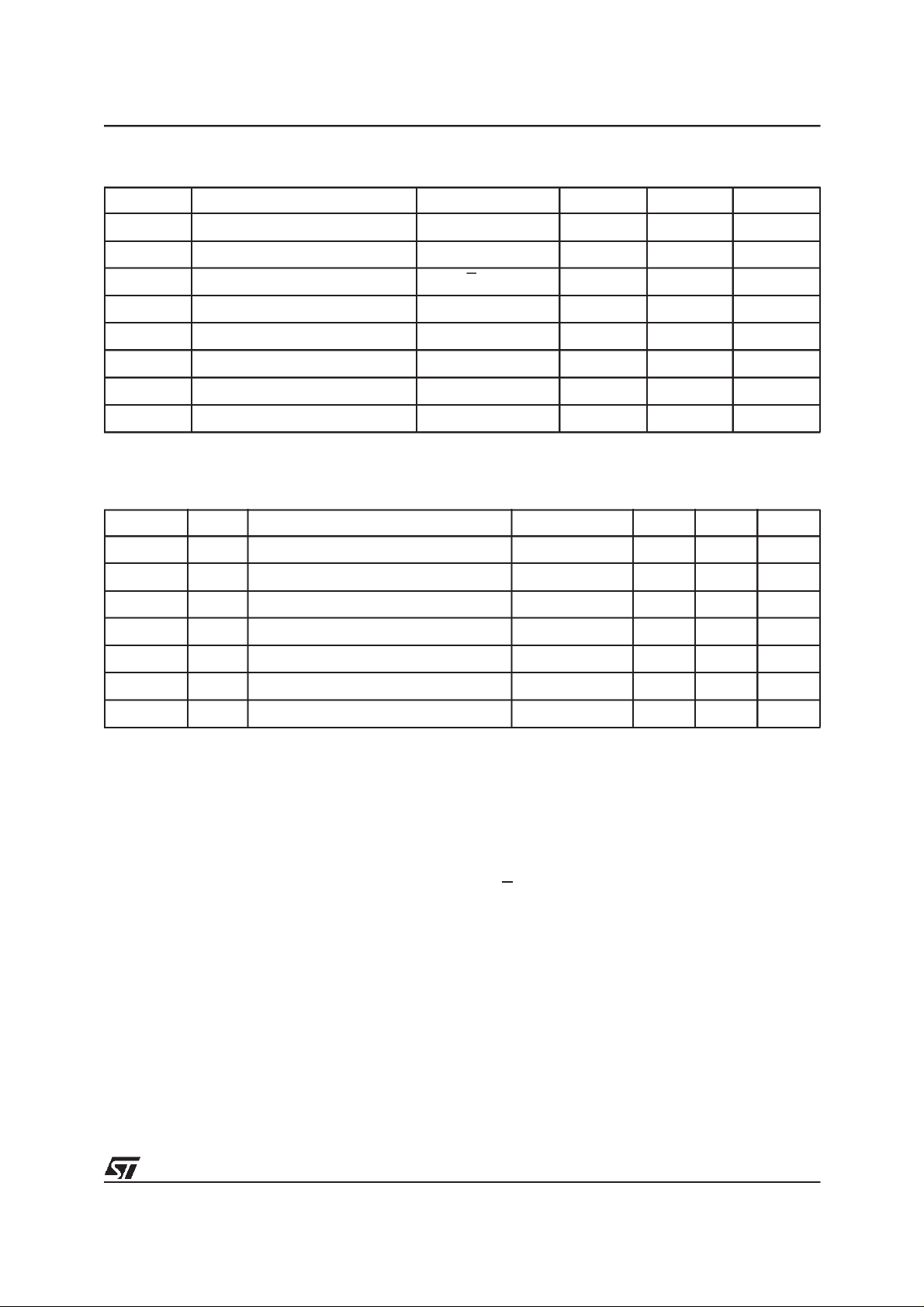
Table 9. Programming Mode DC Characteristics
(1)
(TA=25°C; VCC= 6.25V±0.25V; VPP= 12.75V±0.25V)
Symbol Parameter Test Condition Min Max Unit
I
LI
I
CC
I
PP
V
IL
V
IH
V
OL
V
OH
V
ID
Note: 1. VCCmust be applied simultaneously with or before VPPand removed simultaneously or after VPP.
Input Leakage Current
Supply Current 50 mA
Program Current
Input Low Voltage –0.3 0.8 V
Input High Voltage 2 VCC+ 0.5 V
Output Low Voltage
Output High Voltage TTL IOH= –1mA 3.6 V
A9 Voltage 11.5 12.5 V
Table 10. MARGIN MODE AC Characteristics
V
(1)
≤ VIN≤ V
IL
E=V
I
= 2.1mA
OL
IH
IL
±10 µA
50 mA
0.4 V
(TA=25°C; VCC= 6.25V±0.25V; VPP= 12.75V±0.25V)
Symbol Alt Parameter Test Condition Min Max Unit
t
A9HVPH
t
VPHEL
t
A10HEH
t
A10LEH
t
EXA10X
t
EXVPX
t
VPXA9X
Note: 1. VCCmust be applied simultaneously with or before VPPand removed simultaneously or after V
t
t
t
AS10VA10
t
AS10VA10
t
AH10
t
t
VA9High to VPPHigh
AS9
VPPHigh to Chip Enable Low
VPS
Chip Enable Transition to V
Chip Enable Transition to VPPTransition 2 µs
VPH
VPPTransition to VA9Transition
AH9
High to Chip Enable High (Set)
Low to Chip Enable High (Reset)
Transition
A10
2 µs
2 µs
1 µs
1 µs
1 µs
2 µs
PP.
Programming
The M27W512 hasbeen designed to be fully compatible with the M27C512 and has the same electronic signature. As a result the M27W512 can be
programmed as the M27C512 on the same programming equipmentapplying 12.75V on VPPand
6.25V on VCC. The M27W512 can use PRESTO
IIB Programming Algorithm that drastically reduces the programming time. Nevertheless to achieve
compatibility with all programming equipments,
PRESTO II Programming Algorithm can be used
as well. When delivered (and after each ‘1’s erasure for UV EPROM), all bits of the M27W512 are
in the ’1’ state. Data is introduced by selectively
programming ’0’s into the desired bit locations. Although only ’0’swill be programmed, both ’1’s and
’0’scan be present in the data word. The only way
to change a ‘0’ to a ‘1’s by die exposure to ultraviolet light (UV EPROM). The M27W512 is in the
programming mode when VPPinput is at 12.75V
and E is pulsed to VIL. The data to be programmed
is applied to 8 bits in parallel to the data output
pins. The levels required for the address and data
inputs are TTL. VCCis specified to be 6.25V ±
0.25V.
7/16
Page 8
M27W512
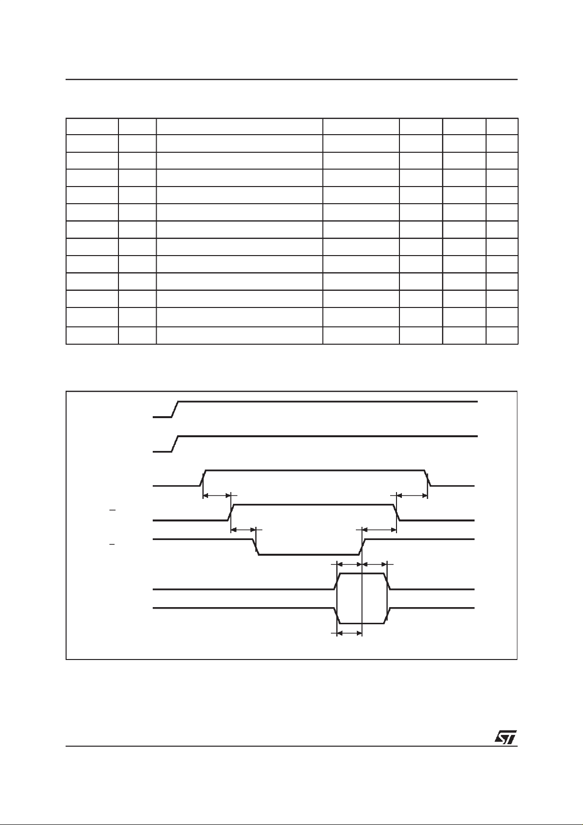
Table 11. Programming Mode AC Characteristics
(1)
(TA=25°C; VCC= 6.25V±0.25V; VPP= 12.75V±0.25V)
Symbol Alt Parameter Test Condition Min Max Unit
t
AVEL
t
QVEL
t
VCHEL
t
VPHEL
t
VPLVPH
t
ELEH
t
EHQX
t
EHVPX
t
VPLEL
t
ELQV
(2)
t
EHQZ
t
EHAX
Note: 1. VCCmust be applied simultaneously with or before VPPand removed simultaneously or after VPP.
2. Sampled only, not 100% tested.
t
t
t
VCS
t
OES
t
PRT
t
t
t
OEH
t
t
t
DFP
t
Address Validto Chip Enable Low 2 µs
AS
Input Valid to Chip Enable Low 2 µs
DS
VCCHigh to Chip Enable Low
VPPHigh to Chip Enable Low
2 µs
2 µs
VPPRise Time 50 ns
Chip Enable Program Pulse Width (Initial) 95 105 µs
PW
Chip Enable High to Input Transition 2 µs
DH
Chip Enable High to VPPTransition
VPPLow to Chip Enable Low
VR
Chip Enable Low to Output Valid 1 µs
DV
2 µs
2 µs
Chip Enable High to Output Hi-Z 0 130 ns
Chip Enable High to Address Transition 0 ns
AH
Figure 6. MARGIN MODE AC Waveforms
V
CC
A8
A9
tA9HVPH tVPXA9X
GV
PP
E
A10 Set
A10 Reset
Note: A8 High level = 5V; A9 High level = 12V.
tVPHEL
tA10HEH
tA10LEH
tEXVPX
tEXA10X
AI00736B
8/16
Page 9
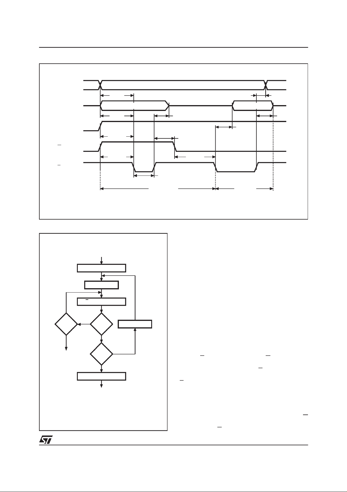
Figure 7. Programming and Verify Modes AC Waveforms
M27W512
A0-A15
tAVEL
Q0-Q7
tQVEL
V
CC
tVCHEL
GV
PP
tVPHEL
E
Figure 8. Programming Flowchart
VCC= 6.25V, VPP= 12.75V
SET MARGIN MODE
n=0
E = 100µs Pulse
NO
NO
VERIFY
YES
Last
NO
Addr
YES
RESET MARGINMODE
CHECK ALL BYTES
1st: VCC=5V
2nd: VCC= 2.7V
++ Addr
YES
++n
=25
FAIL
DATA IN
AI00738C
tELEH
PROGRAM
VALID
tEHAX
DATA OUT
tEHQX
tELQV
tEHVPX
tVPLEL
VERIFY
tEHQZ
AI00737
PRESTO IIB Programming Algorithm
PRESTO IIB Programming Algorithm allows the
whole array to be programmed with a guaranteed
margin, in a typical time of 6.5 seconds. This can
be achieved with STMicroelectronics M27W512
due to several design innovations described in the
M27W512 datasheet to improve programming efficiency and to provide adequate margin for reliability. Before starting the programming the
internal MARGIN MODE circuit must be set in order toguarantee that each cellis programmed with
enough margin. Then a sequence of 100µs program pulses is applied to each byte until a correct
verify occurs (see Figure 8).No overprogram pulses are applied since the verify in MARGIN MODE
at VCCmuch higher than 3.6V, provides the necessary margin.
Program Inhibit
Programming of multiple M27W512s in parallel
with different data is also easily accomplished. Except for E, alllike inputsincluding GVPPof the parallel M27W512 may be common. A TTL low level
pulse applied to a M27W512’s E input, with VPPat
12.75V, will program that M27W512. A high level
E input inhibits the other M27W512s from being
programmed.
Program Verify
A verify (read) should be performed on the programmed bits to determine that they were correctly programmed. The verify is accomplished with G
at VIL. Data should be verified with t
ELQV
after the
falling edge of E.
9/16
Page 10

M27W512
On-Board Programming
The M27W512 can be directly programmed in the
application circuit. See the relevant Application
Note AN620.
Electronic Signature
The Electronic Signature (ES) mode allows the
reading out of a binary code from an EPROM that
will identify its manufacturer and type. This mode
is intended for use by programming equipment to
automatically match the device to be programmed
with its corresponding programming algorithm.
The ES mode is functional in the 25°C±5°C ambient temperature range thatis requiredwhen programming the M27W512. To activate the ES
mode, the programming equipment must force
11.5V to 12.5V on address line A9 of the
M27W512. Two identifier bytes may then be sequenced from the device outputs by toggling address line A0 from VILto VIH. All other address
lines must be held at VILduring Electronic Signature mode. Byte 0 (A0 = VIL) represents the manufacturer code and byte 1 (A0 = VIH) the device
identifier code. For the STMicroelectronics
M27W512, these two identifier bytes are given in
Table 4and can be read-out on outputs Q7 to Q0.
Note that the M27W512 and M27C512 have the
same identifier byte.
ERASURE OPERATION (applies for UV EPROM)
The erasure characteristics of the M27W512 is
such that erasure begins when the cells are exposed to light with wavelengths shorter than approximately 4000 Å. It should be noted that
sunlight and some type of fluorescent lamps have
wavelengths in the 3000-4000 Å range.
Research shows that constant exposure to room
level fluorescent lighting could erase a typical
M27W512 in about 3 years, while it would take approximately 1 week to cause erasure when exposed to direct sunlight. If the M27W512 is to be
exposed to these types of lighting conditions for
extended periods of time, it is suggested that
opaque labels be put over the M27W512 window
to prevent unintentional erasure. The recommended erasure procedure for the M27W512 is exposure to short wave ultraviolet light which has
wavelength 2537 Å. The integrated dose (i.e. UV
intensity x exposure time) for erasure should be a
minimum of 15 W-sec/cm2. The erasure time with
this dosage is approximately 15 to 20 minutes using an ultraviolet lamp with 12000µW/cm2power
rating. The M27W512 should be placed within 2.5
cm (1 inch) of the lamp tubes during the erasure.
Some lamps have a filter on their tubes which
should be removed before erasure.
10/16
Page 11
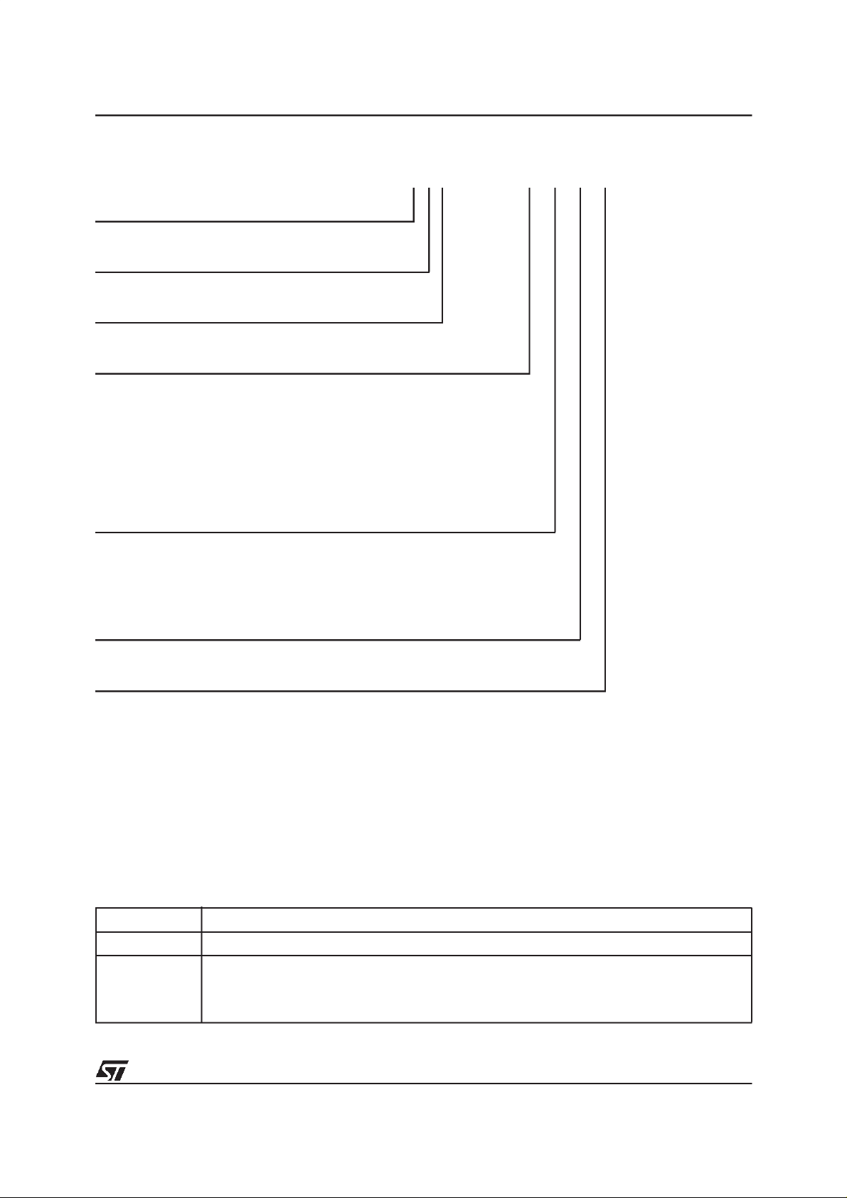
Table 12. OrderingInformation Scheme
Example: M27W512 -80 K 6 TR
Device Type
M27
Supply Voltage
W = 2.7V to 3.6V
Device Function
512 = 512 Kbit (64Kb x 8)
Speed
(1,2)
-80
-100 = 100 ns
=80ns
M27W512
Not For New Design
(3)
-120 = 120 ns
-150 = 150 ns
-200 = 200 ns
Package
F = FDIP28W
(4)
B = PDIP28
K = PLCC32
N = TSOP28: 8 x 13.4 mm
(4)
Temperature Range
6=–40to85°C
Options
TR = Tape& Reel Packing
Note: 1. High Speed, see AC Characteristics section for further information.
2. This speed also guarantees 70ns access time at V
3. These speeds are replaced by the 100ns.
4. Packages option available on request. Please contact STMicroelectronics local Sales Office.
= 3.0V to 3.6V.
CC
For a list of available options (Speed, Package, etc...) or for further information on any aspect of this device, please contact the STMicroelectronics Sales Office nearest to you.
Table 13. Revision History
Date Revision Details
July 1999 First Issue
FDIP28W Package Dimension, L Max added (Table 14)
03/20/00
TSOP32 Package Dimension changed (Table 17)
0to70°C Temperature Range deleted
Speed Classes changed
11/16
Page 12
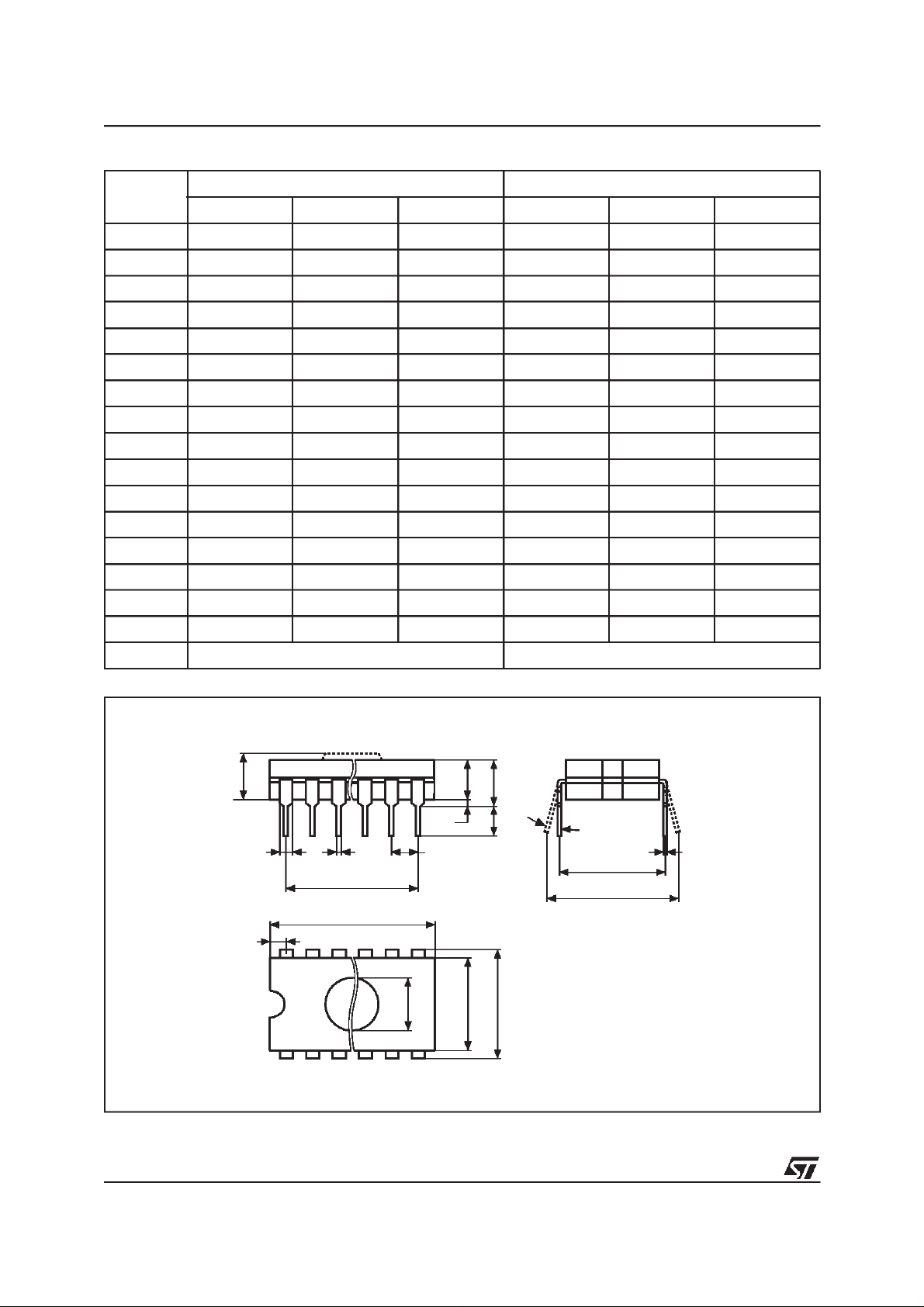
M27W512
Table 14. FDIP28W - 28 pin Ceramic Frit-seal DIP, with window, Package Mechanical Data
Symbol
Typ Min Max Typ Min Max
A 5.71 0.225
A1 0.50 1.78 0.020 0.070
A2 3.90 5.08 0.154 0.200
B 0.40 0.55 0.016 0.022
B1 1.17 1.42 0.046 0.056
C 0.22 0.31 0.009 0.012
D 38.10 1.500
E 15.40 15.80 0.606 0.622
E1 13.05 13.36 0.514 0.526
e1 2.54 – – 0.100 – –
e3 33.02 – – 1.300 – –
eA 16.17 18.32 0.637 0.721
L 3.18 4.10 0.125 0.161
S 1.52 2.49 0.060 0.098
∅ 7.11 – – 0.280 – –
α 4° 15° 4° 15°
mm inches
N28 28
Figure 9. FDIP28W - 28 pin Ceramic Frit-seal DIP, with window, Package Outline
A2
B1 B e
A3A1A
L
α
C
eA
D2
eB
D
S
N
∅
1
E1 E
FDIPW-a
Drawing is not to scale.
12/16
Page 13
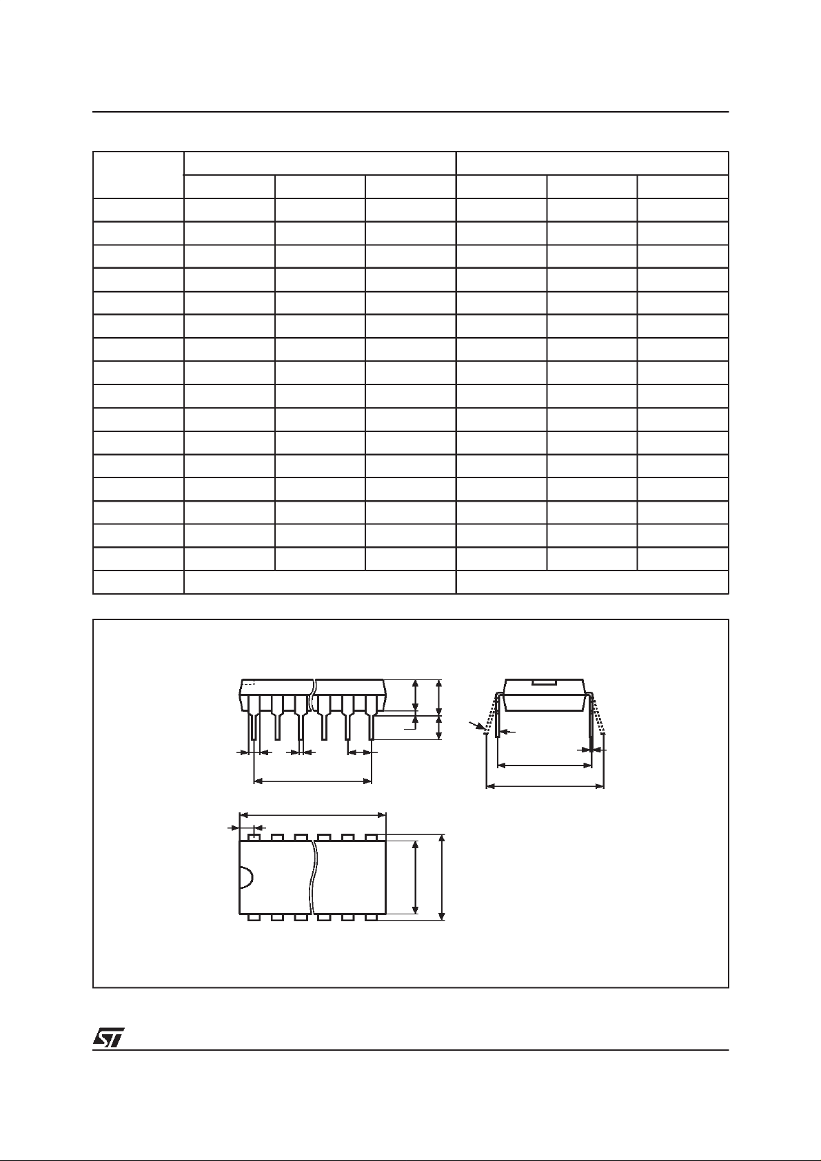
Table 15. PDIP28 - 28 pin Plastic DIP, 600 mils width, Package Mechanical Data
mm inches
Symbol
Typ Min Max Typ Min Max
A – 5.08 – 0.200
A1 0.38 – 0.015 –
A2 3.56 4.06 0.140 0.160
B 0.38 0.51 0.015 0.020
B1 1.52 – – 0.060 – –
C 0.20 0.30 0.008 0.012
D 36.83 37.34 1.450 1.470
D2 33.02 – – 1.300 – –
E 15.24 – – 0.600 – –
E1 13.59 13.84 0.535 0.545
e1 2.54 – – 0.100 – –
eA 14.99 – – 0.590 – –
eB 15.24 17.78 0.600 0.700
L 3.18 3.43 0.125 0.135
S 1.78 2.08 0.070 0.082
α 0° 10° 0° 10°
M27W512
N28 28
Figure 10. PDIP28 - 28 pin Plastic DIP, 600 mils width, Package Outline
A2A1A
L
B1 B e1
D2
α
C
eA
eB
D
S
N
E1 E
1
PDIP
Drawing is not to scale.
13/16
Page 14
M27W512
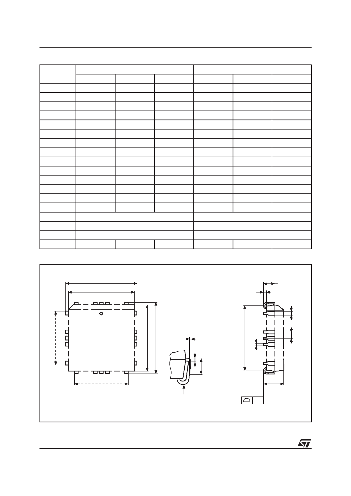
Table 16. PLCC32 - 32 lead Plastic Leaded Chip Carrier, Package Mechanical Data
Symbol
A 2.54 3.56 0.100 0.140
A1 1.52 2.41 0.060 0.095
A2 – 0.38 – 0.015
B 0.33 0.53 0.013 0.021
B1 0.66 0.81 0.026 0.032
D 12.32 12.57 0.485 0.495
D1 11.35 11.56 0.447 0.455
D2 9.91 10.92 0.390 0.430
E 14.86 15.11 0.585 0.595
E1 13.89 14.10 0.547 0.555
E2 12.45 13.46 0.490 0.530
e 1.27 – – 0.050 – –
F 0.00 0.25 0.000 0.010
R 0.89 – – 0.035 – –
N32 32
Nd 7 7
Ne 9 9
CP 0.10 0.004
Typ Min Max Typ Min Max
mm inches
Figure 11. PLCC32 - 32 lead Plastic Leaded Chip Carrier, Package Outline
D
D1
1N
Ne E1 E
F
D2/E2
0.51 (.020)
1.14 (.045)
Nd
R
PLCC
Drawing is not to scale.
A1
A2
B1
e
B
A
CP
14/16
Page 15
M27W512
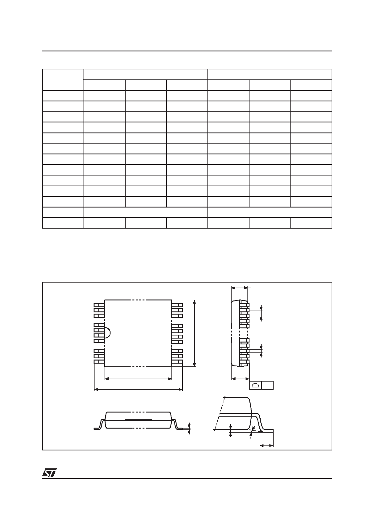
Table 17. TSOP28 - 28 lead Plastic Thin Small Outline, 8 x 13.4 mm, Package Mechanical Data
Symbol
Typ Min Max Typ Min Max
A 1.250 0.0492
A1 0.200 0.0079
A2 0.950 1.150 0.0374 0.0453
B 0.170 0.270 0.0067 0.0106
C 0.100 0.210 0.0039 0.0083
D 13.200 13.600 0.5197 0.5354
D1 11.700 11.900 0.4606 0.4685
e 0.550 – – 0.0217 – –
E 7.900 8.100 0.3110 0.3189
L 0.500 0.700 0.0197 0.0276
α 0° 5° 0° 5°
N28 28
CP 0.100 0.0039
mm inch
Figure 12. TSOP28 - 28 lead Plastic Thin Small Outline, 8 x 13.4 mm, Package Outline
A2
22
21
e
28
1
E
B
78
D1
D
DIE
A
CP
C
TSOP-c
Drawing is not to scale.
LA1 α
15/16
Page 16

M27W512
Information furnished is believed tobe accurate and reliable. However, STMicroelectronics assumes no responsibility for the consequences
of use ofsuch information nor for any infringement of patents or other rights of third parties which may result from its use. No license is granted
by implication or otherwise under any patent or patent rights of STMicroelectronics. Specifications mentioned in this publication are subject
to change without notice. This publication supersedes and replaces all information previously supplied. STMicroelectronics products are not
authorized for use as critical components in lifesupport devices or systems without express written approval of STMicroelectronics.
The ST logo is registered trademark of STMicroelectronics
2000 STMicroelectronics - All Rights Reserved
All other names are the property of their respective owners.
Australia - Brazil - China - Finland - France - Germany - Hong Kong - India - Italy - Japan - Malaysia - Malta - Morocco -
Singapore - Spain - Sweden - Switzerland - United Kingdom - U.S.A.
STMicroelectronics GROUP OF COMPANIES
http://www.st.com
16/16
 Loading...