

Page 1
P ATENTS PENDING
LIN DOC #:
1640
LXM1640-01
DIRECT DRIVE QUAD LAMP CCFL INVERTER MODULE
THE INFINITE POWER OF INNOVATION
DESCRIPTION KEY FEATURES
The Quad Output Module Ideal for
Desktop and Industrial Applications.
The LXM1640 Direct Drive
TM
Cold Cathode
Fluorescent Lamp (CCFL) Inverter is a single
module designed to drive four lamps and
is targeted for use with desktop Liquid Crystal Display (LCD) and industrial LCD panels typically ranging in size from 14-inches
to 21-inches. This four output inverter is
the ideal solution to power virtually any
four lamp application.
Direct Drive Technology. The module design is based on a new Direct Drive
topology, which provides a number of cost
and performance advantages. The
LXM1640-01 Direct Drive inverters eliminate
the classic resonant inductor and capacitors, thus reducing cost and allowing a substantial reduction in module size.
Fixed-Frequency Operation. Other
benefits of this new topology are fixed-frequency operation and secondary-side
strike-voltage regulation. Strike-voltage
regulation minimizes corona discharge in
the output transformer and related circuitry,
providing longer life and higher reliability.
Fail-safe Feature For Multiple Lamp
Applications. Our multi-output inverters
are designed to keep your application op-
erating at near normal brightness in the
event that a lamp fails. This allows the
display to remain "on-line" until lamp replacement is convenient.
Quad Module Uses Standard Power
Supply. The LXM1640 module uses a stan-
dard 12V input supply. It also ensures
nominal power consumption with 4 lamps
requiring only 16 watts. Lamp current is
fully regulated with respect to input voltage and output impedance variations.
Dimming Features. The LXM1640 modules are equipped with a dimming input
that permits brightness control from an
external potentiometer or DC voltage. In
addition, the sleep input reduces module
power to a few microwatts in shut down
mode. All LXM1640 modules feature both
output open and short-circuit protection.
The Most Efficient and Cost-effective
Backlight Inverter for Desktop/Industrial Applications. Linfinity's proprietary
Direct Drive architecture is the highest efficiency, small form factor solution for all
multiple lamp applications. The LXM1640
is fully customizable (electronically and mechanically) to specific customer requirements.
P RELIMINARY DATA SHEET
■ Drive Four Lamps With One Module
■ Small, Compact Size
■ High Efficiency
■ Multiple Output Connectors Provide Easy
LCD Connections
■ Low EMI And Noise
■ Low Power Sleep Mode
■ Output Short And Open Circuit Protection
■ 3:1 Dimming Control
■ Adjustable Lamp Current Up To 6.0mA Per
Lamp
■ Long Lamp Life With Soft-Start And
Accurate Lamp Current Regulation
APPLICATIONS
■■
■ Desktop LCD Monitors And Panels
■■
■■
■ Industrial LCD Panels
■■
■■
■ Hi-Brite Displays
■■
BENEFITS
■■
■ Cool Operation
■■
■■
■ Smooth, Easy-To-Use Brightness Control
■■
■■
■ Single 12 Volt Supply
■■
IMPORTANT: For the most current data, consult LinFinity's web site: http://www.linfinity.com.
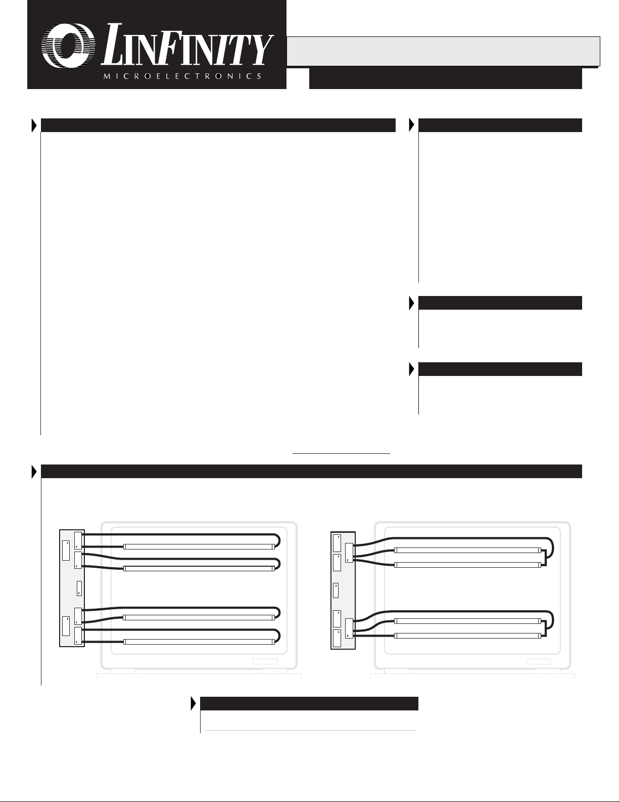
PRODUCT HIGHLIGHT
LXM1640 "UNIVERSAL" MODULE CONNECTION OPTIONS
Quad Connector Configuration Dual Connector Configuration
CN7CN6
CN2
CN5 CN4
CN1
LXM1640-01
CN3
CN7 CN6
CCFL Lamps
Desktop Display
MODULE ORDER INFORMATION
LXM1640-01
CN3
CN1
LXM1640-01
CN5CN4
CN2
CCFL Lamps
Desktop Display
Copyright © 1998
Rev. 0.4 5/98
L INFINITY MICROELECTRONICS INC.
11861 WESTERN AVENUE, GARDEN GROVE, CA. 92841, 714-898-8121, FAX: 714-893-2570
1
Page 2
PRODUCT DATABOOK 1996/1997
LXM1640-01
DIRECT DRIVE QUAD LAMP CCFL INVERTER MODULE
RELIMINARY DATA SHEET
P
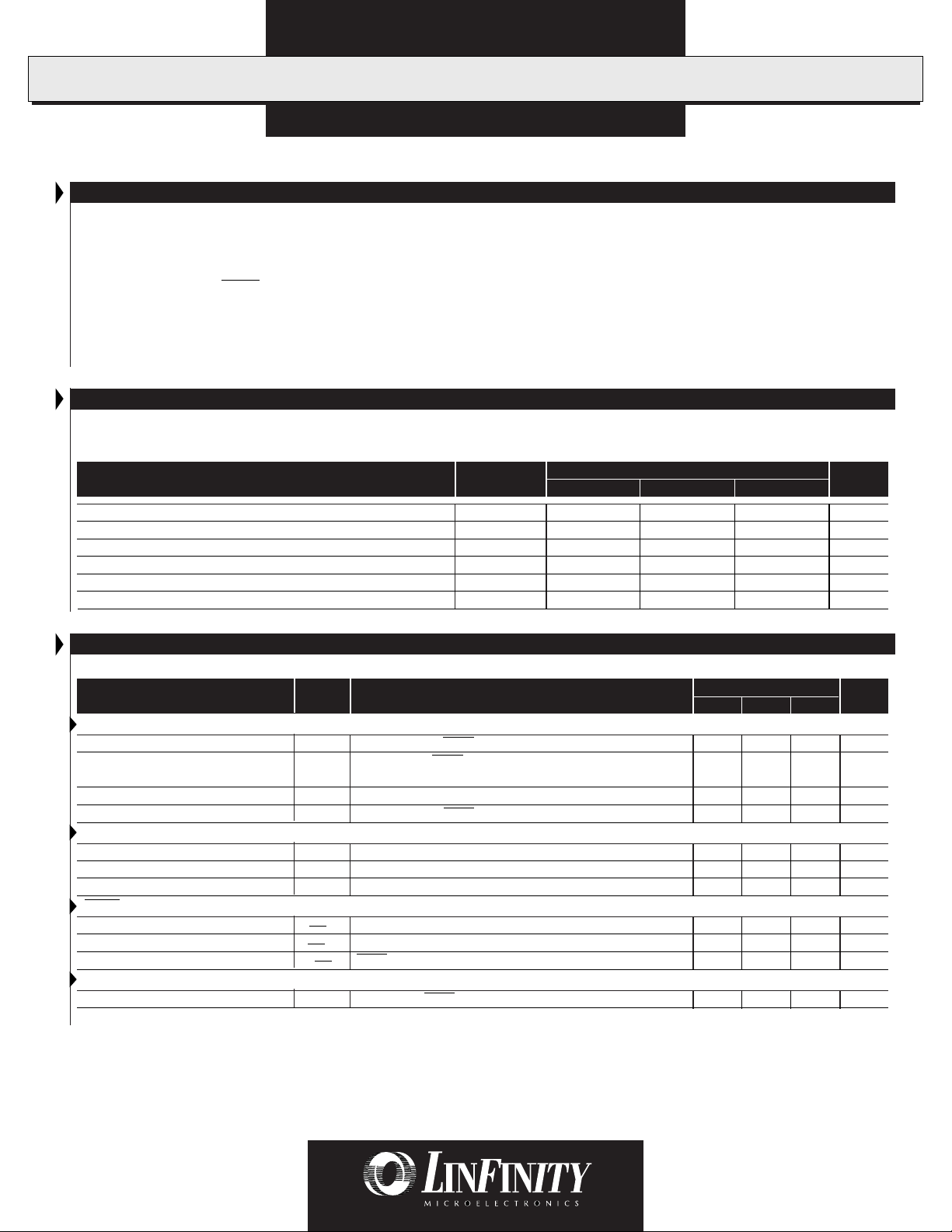
ABSOLUTE MAXIMUM RATINGS (Note 1)
Input Supply Voltage (VIN)....................................................................................................................................................... -0.3V to 16V
Output Voltage, no load .............................................................................................................................. Internally Limited to 1800V
Output Current (per Lamp) ........................................................................................................................ 10.0mA
Output Power (per Lamp) .................................................................................................................................................................... 6.0W
Input Signal Voltage, (SLEEP and BRITE Inputs) ..................................................................................................................... -0.3V to V
Ambient Operating Temperature, zero airflow ........................................................................................................................0°C to 40°C
Storage Temperature Range................................................................................................................................................... -40°C to 85°C
Note 1. Exceeding these ratings could cause damage to the device. All voltages are with respect to Ground. Currents are positive into, negative
out of the specified terminal.
RECOMMENDED OPERATING CONDITIONS (R.C.)
This module has been designed to operate over a wide range of input and output conditions. However, best efficiency and performance
will be obtained if the module is operated under the condition listed in the 'R.C.' column. Min. and Max. columns indicate values beyond
which the inverter, although operational, will not function optimally.
Parameter
Symbol
Input Supply Voltage Range (Functional) V
Output Power (per Lamp) P
Brightness Control Input Voltage Range V
Lamp Operating Voltage V
Lamp Current (Full Brightness - per Lamp) I
Operating Ambient Temperature Range T
IN
O
BRT ADJ
LAMP
OLAMP
A
Recommended Operating Conditions
Min. R.C. Max.
10.8 12 13.2 V
45W
0.0 5.0 V
300 675 800 V
6.0 mA
040°C
(Internally Limited)
RMS
RMS
IN
Units
RMS
RMS
ELECTRICAL CHARACTERISTICS
Unless otherwise specified, these specifications apply over the recommended operating conditions and 25°C ambient temperature for the LXM1640.
Parameter
Symbol
Test Conditions Units
LXM1640-01
Min. Typ. Max.
Output Pin Characteristics
Full Bright Lamp Current (per Lamp) I
Minimum Lamp Current (per Lamp) I
(Note 2)
Lamp Start Voltage V
Operating Frequency f
L (MAX)VBRT ADJ
L (MIN)VBRT ADJ
LS
O
= 5.0VDC, SLEEP = HIGH, VIN = 12V
= 0VDC, SLEEP = HIGH, VIN = 12V
0°C < TA < 40°C, V
V
= 5.0VDC, SLEEP = HIGH, VIN = 12V
BRT ADJ
≥ 10.8V
IN
DC
DC
DC
DC
5.4 6.0 6.6 mA
0.5 mA
1500 1800 V
52 57 62 KHz
BRITE Input
Input Current I
Input Voltage for Max. Lamp Current V
Input Voltage for Min. Lamp Current V
V
BRT ADJ
I
O (LAMP)
I
O (LAMP)
= 0V
DC
= 100%
= Minimum
BRT
C
C
27 30 33 µA
5.0 V
0V
SLEEP Input
RUN Mode V
SLEEP Mode V
Input Current I
SLEEP (HI)
SLEEP (LO)
SLEEP
SLEEP = 5.0V
2.2 V
IN
-0.3 0.8 V
90 110 150 µA
Power Characteristics
Sleep Current I
IN (MIN)VIN
Note 2. Minimum lamp current required to maintain even light output may vary with display panel.
= 12VDC , SLEEP = 0V
DC
0 10 500 µA
RMS
RMS
RMS
DC
DC
DC
V
DC
DC
DC
DC
2
Copyright © 1998
Rev. 0.4 5/98
Page 3

PRODUCT DATABOOK 1996/1997
0
DIRECT DRIVE QUAD LAMP CCFL INVERTER MODULE
Conn. Pin Description
CN1
CN1-1
CN1-2
CN1-3
CN1-4
CN1-5 SLEEP
CN1-6 BRITE
CN1-7 N.C.
CN1-8 N.C.
CN2 and CN3: Refer to Figure 1
V
IN
GND
Input Power Supply. (10.8V ≤ VIN ≤ 13.2V)
Power Supply Return.
ON/OFF Control. (2.2V < SLEEP < V
Brightness Control (-0.3V to 5.0V
No Connect.
No Connect.
P RELIMINARY DATA SHEET
FUNCTIONAL PIN DESCRIPTION
= ON, -0.3V < SLEEP < 0.8V = OFF)
IN
). 5.0VDC gives maximum lamp current.
DC
LXM1640-01
.016 (4)
0.94
(24)
0.32 (8.25)
0.46 (11.8)
PHYSICAL DIMENSIONS
LXM1640-01
All dimensions are in inches (mm)
6.89 (175)
6.73 (171)
Ø 0.118 (3.0) Mtg. Hole, 2 Places
CN3 CN2
CN1
CN7 CN4CN5
CN6
0.016
(4)
0.33 (8.5)
0.06 (1.52)
Copyright © 1998
Rev. 0.4 5/98
3
Page 4

LXM1640-01
PRODUCT DATABOOK 1996/1997
DIRECT DRIVE QUAD LAMP CCFL INVERTER MODULE
RELIMINARY DATA SHEET
P
CONNECTOR SCHEMATIC
CN4
CN5
123
N.C.
1234
CN2
12
Inverter
Output 1
V
HI1
Inverter
Output 2
CN1
81
V
HI2
V
Inverter
Output 3
CN6
12
V
HI3
HI4
Inverter
Output 4
1234
N.C.
CN7
2
13
CN3
FIGURE 1 — LXM1640-01 Connector Schematic
Connectors: Mates With:
CN1 = MOLEX 53261-0890 Pins: 50079-8100*, Housing: 51021-0800
* Loose (-8000, Chain) Recommended #26 AWG wiring
CN2, CN3 = JST SM04(4.0)B-BHS-1-TB JST BHR-04VS-1
CN4, CN7 = JST SM03(4.0)B-BHS-1-TB JST BHR-03VS-1
CN5, CN6 = JST SM02(8.0)B-BHS-1-TB JST BHR-03VS-1
Connection Rules
1. Always install four (4) lamps. Operating with out all lamps may overdrive lamp current at maximum brightness settings.
2. Verify lamp wiring before connecting lamps to the inverter module. Connecting more than one lamp to one of the four inverter output
circuits will result in reduced brightness. The LXM1640-01 module connectors are wired per industry standard. The lamp hot wires
(high voltage wires) are always on pin 1 or 2, and the cold wire (low voltage wire) is always on pin 3 or 4.
FAILSAFE FEATURE FOR MULTIPLE LAMP OPERATIONS
Our multi-output inverters are designed to keep your application
operating at near normal brightness in the event that a lamp fails.
This allows the display to remain "on-line" until lamp replacement
is convenient.
Linfinity "pairs" the lamps so that if one lamp in the pair breaks,
most of its current is added to the good lamp. CCFLs will respond
with more brightness for a period of time. Operating time in this
mode will be a function of the lamps age but should be typically
in the order of hundreds of hours.
This operating characteristic can provide adequate display
performance for a limited, but useful period of time. Shortening
of the lamp life in this mode is typically not a concern as it is
recommended that
all lamps in a display be replaced at the same
time.
4
Lamps
I
S
FIGURE 2 — Quad Output Stage
Copyright © 1998
Rev. 0.4 5/98
Page 5

PRODUCT DATABOOK 1996/1997
DIRECT DRIVE QUAD LAMP CCFL INVERTER MODULE
P RELIMINARY DATA SHEET
DIRECT DRIVE OUTPUT ARCHITECTURE
LXM1640-01
Direct Drive architecture includes two load feedback control loops
to provide uncompromised CCFL ignition and operation characteristics.
Lamp current is regulated in the CCFL return lead (I
insure constant light output with changing lamp parameters and
loop) to
SNS
power supply voltage. This also allows accurate and repeatable
brightness control. Dimming ratio with the LX1640 analog dimming
inverters is typically 6:1 when driving quad LCD lamp panels.
SLEEP
Transformer
BRITE
GND
Controller
Driver
I
SENSE
FIGURE 3 — LXM1640 Block Diagram
(Only one lamp shown)
If no current flows in the CCFL return path because of an
unstruck or failed lamp, the inverter applies full strike voltage
potential. The output voltage feedback loop (V
and regulates output voltage to 1650V
ignite under worst case temperature and aging conditions.
. This insures lamps will
RMS
) takes control
SNS
Because output voltage is actively regulated, it will never exceed
component and panel insulation ratings. This prevents destructive
corona discharge to insure long term reliability of the system.
High Voltage
Transformer
V
HI1
LAMP 1
V
SENSE
V
LO
TYPICAL APPLICATIONS
≤10k
5.0V
10.8VDC- 13.2V
DC
V
BRITE
DC
V
IN
HI4
V
HI3
V
HI2
V
HI1
LXM1640-01
5V
0V
PRELIMINARY DATA - Information contained in this document is pre-production data, and is proprietary to LinFinity. It may
not modified in any way without the express written consent of LinFinity. Product referred to herein is offered in sample form
only, and Linfinity reserves the right to change or discontinue this proposed product at any time.
SLEEP
GND
V
LO
FIGURE 4 — Potentiometer Brightness Control
Lamp 1
Lamp 2
Lamp 3
Lamp 4
Copyright © 1998
Rev. 0.4 5/98
5
 Loading...