

Page 1
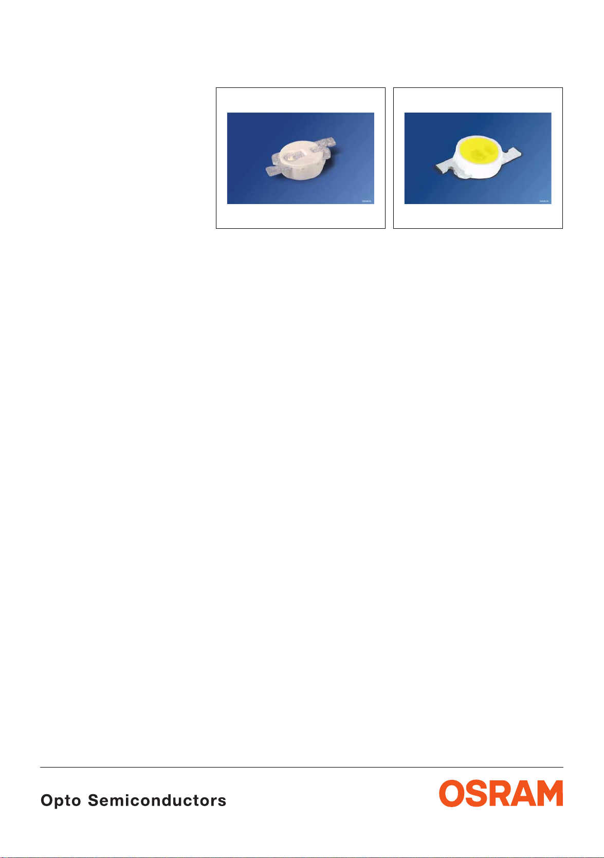
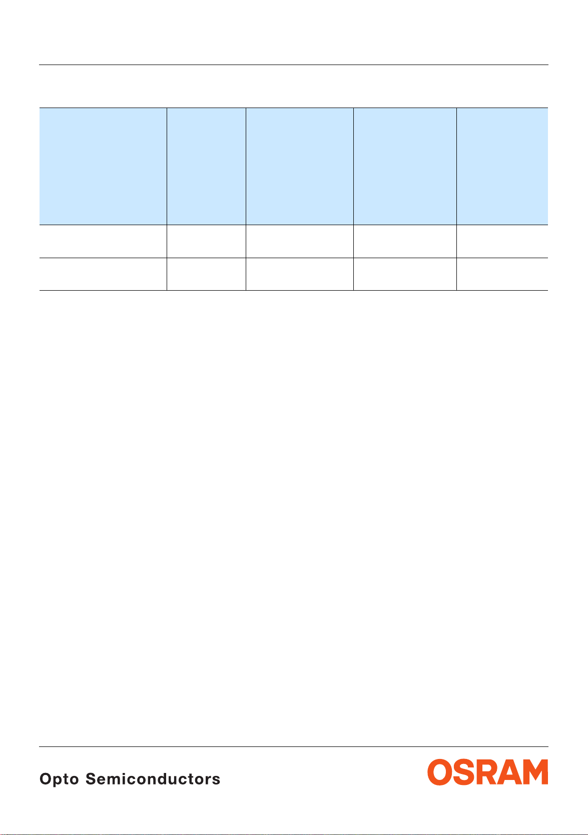
Hyper PointLED
®
long life
Enhanced optical Power LED (ThinGaN
Lead (Pb) Free Product RoHS Compliant
LW P4SG
reverse mount top mount
Vorläufige Daten / Preliminary Data
®
)
Besondere Merkmale
• Gehäusetyp: weißes SMT Gehäuse, eingefärbter
diffuser Silikon - Verguss
• Besonderheit des Bauteils: erhöhte
Lebensdauer durch verb es s ert en Vergus s ;
Montage von unten durch die Leiterplatte oder von
oben möglich; ideal für extrem flache
Hinterleuchtungen
• Farbort: x = 0,33, y = 0,33 nach CIE 1931 (weiß)
• typische Farbtemperatur: 5600 K
• Farbwiedergabeindex: 80
• Abstrahlwinkel: Lambertscher Strahler (120°)
• Technologie: ThinGaN
• optischer Wirkungsgrad: 40 lm/W
• Gruppierungsparameter: Lichtstärke, Farbort,
Durchlassspannung
• Verarbeitungsmethode: für alle
SMT-Bestücktechniken geeignet
• Lötmethode: IR Reflow Löten
• Vorbehandlung: nach JEDEC Level 4
• Gurtung: 12-mm Gurt mit 3000/Rolle, ø180 mm
oder 12000/Rolle, ø330
• ESD-Festigkeit: ESD empfindliches Bauteil nach
JESD22-A114-B ESD Klasse 0
Anwendungen
• Einkopplung in Lichtleiter
• Tastenhinterleuchtung
• optischer Indikator
• Hinterleuchtung (LCD, Handy, Schalter, Tasten,
Allgemeinbeleuchtung)
• Innenbeleuchtung im Automobilbereich
Instrumentenbeleuchtung, u.ä.)
(z.B.
• Blitzlich t im Handy
®
mm
Features
• package: white SMT package, colored diffused
silicone resin
• feature of the device: long lifetime due to
enhanced resin material;
mount; ideal for extremely flat backlight
• color coordi nates: x = 0.33, y = 0.33 acc. to
1931 (white)
CIE
• typ. color temperature: 5600 K
• color reproduction index: 80
• viewing angle: Lambertian Emitter (120°)
• technology: ThinG aN
• optical efficiency: 40 lm/W
• grouping parameter: luminous intensity,
color coordinat es, forward voltage
• assembly methods: suitable for all
assembly methods
SMT
• soldering methods: IR reflow soldering
• preconditioning: acc. to JEDEC Level 4
• taping: 12 mm tape with 3000/reel, ø180 mm
12000/reel, ø330 mm
or
• ESD-withstand voltage: ESD sensitive device
acc. to
Applications
• coupling into light guides
• key pad illumination
• optical indicators
• backlighting (LC D, cellular phones, switches, keys,
general
• interior automotive lighting
(e.g. dashboar d ba ck l ig hti ng , etc.)
JESD22-A114-B ESD class 0
lighting)
top mount or reverse
®
• strobe light for cellular ph ones
2007-03-21 1
Page 2
Bestellinformation Ordering Informarion
Typ
Type
Emissionsfarbe
Color of
Emission
LW P4SG-U2AA-5K8L-1 white
top mount
LW P4SG
1)
Seite 18
Lichtstärke
Luminous
Intensity
1)
I
= 20 mA
F
I
(mcd)
V
page 18
Lichtstrom
Luminous
Flux
I
Φ
2)
= 20 mA
F
(mlm)
V
560 ...1400 2600 (typ.) on request
page 18
2)
Seite 18
Bestellnummer
Ordering Code
LW P4SG-U2AA-5K8L-1 white
560 ...1400 2600 (typ.) Q65110A3637
reverse mount
Anm.: Die oben genannten Typbezeichnungen umfassen die bestellbaren Selektionen. Diese bestehen aus wenigen
Helligkeitsgruppen (sieh e
Gurt geliefert. Z.B.: LW P4SG-U2AA-5K8L bedeutet, dass auf dem Gurt nur eine der H elligkeitsgruppe n U2,
V1, V2 oder AA enthalten ist.
Um die Liefersicherheit zu gew ährleisten, können einzelne H elligkeitsgruppen nicht bes te llt we rden.
Gleiches gilt für die Farben, bei denen Farbortgruppen gemessen und gruppiert werden. Pro Gurt wird nur eine
Farbortgruppe geliefert. Z.B.: LW
-5K, -5L, -6K, -6L, -7K, -7L, -8K od er -8L enthalten ist (siehe
Um die Liefersicherheit zu gew ährleisten, können einzelne F arbortgruppen nicht bestellt werden.
Gleiches gilt für die L EDs, bei den en die Durc hlassspannun gsgruppen g emessen und gruppiert werde n. Pro
Gurt wird nur eine D urchlassspannungsg ruppe geliefert. Z.B.: LW
Durchlassspannung gruppiert wird. Auf einem Gurt ist nur eine der Durchlas spannungsgruppen -4 oder -5
enthalten (siehe
Um die Liefersicher heit zu gewährleisten , können einzelne Durc hlassspannungsgrupp en nicht direkt best ellt
werden.
Note: The above Type Numbers represent the order groups which include only a few brightness groups (see page 6
for explanation). Only o ne group wil l be shipped on each reel (there will be no mixing of two groups on ea ch
reel). E.g. LW
reel.
In order to ensure availability, single brightness groups will not be orderable.
Seite 6 für nähere Information).
P4SG-U2AA-5K8L means that only one group U 2, V1, V2 or A A will be sh ippable for an y one
In a similar manner for colors where chromaticity coordinate groups are measured and binned, single
chromaticity coordinate groups will be shipped on any one reel. E.g. LW
chromaticity coordinate group -5K, -5L, -6K, -6L, -7K, -7L, -8K or -8L will be shippable (see
explanation).
In order to ensure availability, single chromaticity coordinate groups will not be orderable.
In a similar manner for LED , where fo rward volt age group s are m easured and binned , single forward v oltage
groups will be shipped on any one reel. E.g. LW
-4 or -5 will be shippable. In order to ensure availability, single forward voltage groups will not be orderable(see
page 6 for explanation).
Seite 6 für nähere Inform ationen). Es wird nur eine einzige Helligkeitsgruppe pro
P4SG-U2AA-5K8L bedeutet, dass auf dem Gurt nur eine der Farbortgruppen
Seite 5 für nähere Information).
P4SG-U2AA-5K8L-1 b edeutet, dass nach
P4SG-U2AA-5K8L means that only 1
page 5 for
P4SG-U2AA-5K8L-1 means that only 1 forward voltage group
2007-03-21 2
Page 3
Grenzwerte Maximum Ratings
LW P4SG
Bezeichnung
Parameter
Betriebstemperatur
Operating temperature range
Lagertemperatur
Storage temperature range
Sperrschichttemperatur
Junction temperature
Durchlassstrom
Forward current (min.)
(TA=25°C)
Stoßstrom
Surge current
t ≤ 10 µs, D = 0.005, T
3)
Sperrspannung
Reverse voltage3)
Seite 18
page 18
=25°C
A
(TA=25°C)
Leistungsaufnahme
Power consumption
(TA=25°C)
Symbol
Symbol
T
op
T
stg
T
j
I
F
I
F
I
FM
V
R
P
tot
Wert
Value
Einheit
Unit
– 40 … + 100 °C
– 40 … + 100 °C
+ 125 °C
20
5
mA
mA
200 mA
5 V
75 mW
Wärmewiderstand
Thermal resistance
Sperrschicht/Umgebung
4)
Junction/ambient
page 18
Sperrschicht/Lötpad
Junction/solder point
4)
Seite 18
R
R
th JA
th JS
400
240
K/W
K/W
2007-03-21 3
Page 4
Kennwerte
Characteristics
(TA = 25 °C)
LW P4SG
Bezeichnung
Parameter
5)
Farbkoordinate x nach CIE 1931
Chromaticity coordinate x acc. to CIE 1931
I
= 20 mA
F
Farbkoordinate y nach CIE 1931
Chromaticity coordinate y acc. to CIE 1931
I
= 20 mA
F
Seite 18
5)
Seite 18
(typ.)
5)
page 18
(typ.)
5)
page 18
Abstrahlwinkel bei 50 % IV (Vollwinkel) (typ.)
Viewing angle at 50 % I
Durchlassspannung
Forward voltage
I
= 20 mA (max.)
F
6)
6)
Seite 18
page 18
V
(min.)
(typ.)
Sperrstrom (typ.)
Reverse current (max.)
V
= 5 V
R
Temperaturkoeffizient von x (typ.)
Temperature coefficient of x
I
= 20 mA; –10°C ≤ T ≤ 100°C
F
Temperaturkoeffizient von y (typ.)
Temperature coefficient of y
I
= 20 mA; –10°C ≤ T ≤ 100°C
F
Temperaturkoeffizient von V
Temperature coefficient of V
I
= 20 mA; –10°C ≤ T ≤ 100°C
F
F
F
(typ.)
Optischer Wirkungsgrad (typ.)
Optical efficiency
I
= 20 mA
F
* Einzelgruppen siehe Seit e 5
Individual groups on page 5
Symbol
Symbol
Wert
Value
x 0.33* –
y 0.33* –
2ϕ 120 Grad
V
V
V
I
R
I
R
TC
TC
TC
η
F
F
F
x
y
V
opt
2.9
3.2
3.7
0.01
10
–0.2 10-3/K
–0.2 10-3/K
– 4.0 mV/K
40 lm/W
Einheit
Unit
deg.
V
V
V
µA
µA
2007-03-21 4
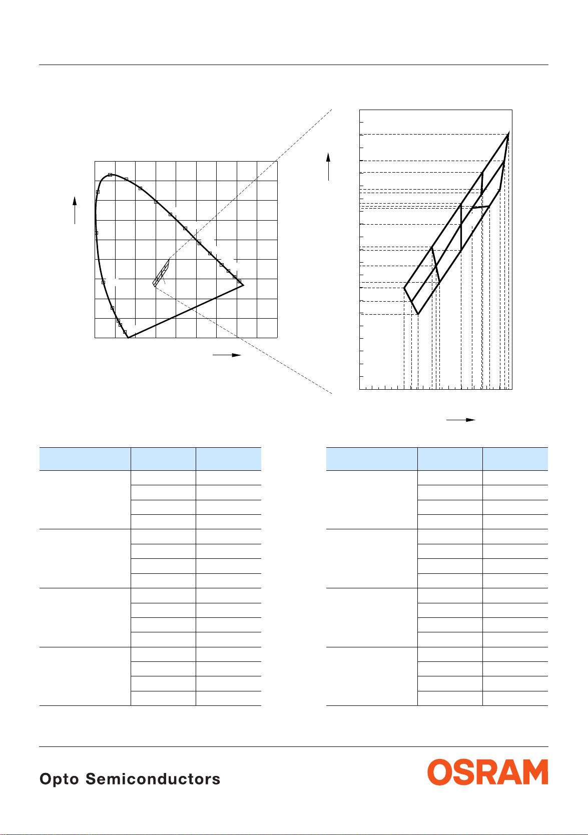
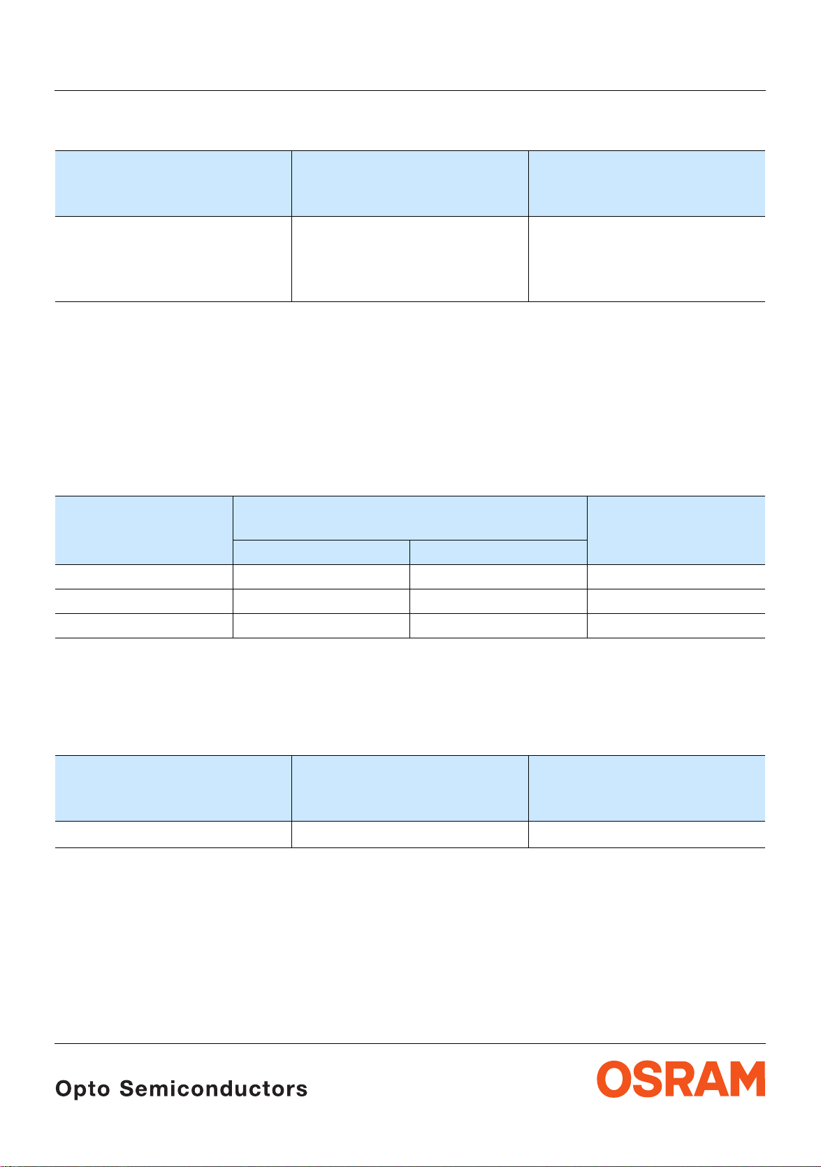
Page 5
LW P4SG
5)
Seite 18
Farbortgruppen
Chromaticity Coordinate Groups
5)
page 18
0.42
0.41
0.40
Cy
0.39
0.38
0.37
0.36
0.35
0.34
0.33
0.32
0.31
0.30
0.29
0.28
0.27
0.26
0.25
0.24
0.23
5L
5K
6L
6K
+
8K
7L
7K
Cy
0.9
520
0.8
0.7
0.6
0.5
0.4
0.3
0.2
0.1
0
530
480
470
460
540
550
560
570
580
590
+
E
450
510
500
490
0
0.1 0.2 0.3 0.4 0.5 0.6 0.7 0.8 0.9
600
610
620
630
Cx
0.22
0.21
0.20
0.31
0.25
0.26
0.27
0.28
0.29
0.30
0.32
0.33
0.34
Cx
OHA13327
Gruppe
Group
5K 0.296 0.259 7K 0.330 0.310
5L 0.291 0.268 7L 0.330 0.330
6K 0.313 0.284 8K 0.352 0.344
6L 0.310 0.297 8L 0.345 0.352
Cx Cy Gruppe
Group
0.291 0.268 0.330 0.330
0.310 0.297 0.338 0.342
0.313 0.284 0.352 0.344
0.285 0.279 0.330 0.347
0.307 0.312 0.347 0.371
0.310 0.297 0.345 0.352
0.310 0.297 0.338 0.342
0.330 0.330 0.364 0.380
0.330 0.310 0.360 0.357
0.307 0.312 0.347 0.371
0.330 0.347 0.367 0.401
0.330 0.330 0.364 0.380
Cx Cy
8L
0.35
0.36
0.37
2007-03-21 5
Page 6
LW P4SG
Helligkeits-Gruppierungsschema Brightness Groups
1)
Seite 18
Helligkeitsgruppe
Brightness Group
U2
V1
V2
AA
Lichtstärke
Luminous Intensity
I
(mcd)
V
560 ... 710
710 ... 900
900 ... 1120
1120 ... 1400
1)
page 18
Luminous Flux
Φ
(mlm)
V
1900 (typ.)
2400 (typ.)
3000 (typ.)
3700 (typ.)
Lichtstrom
Anm.: Die Standardlieferform von Serientypen beinhaltet e ine Familiengruppe. D iese besteht au s nur
Helligkeitsgruppen.
4
Einzelne Helligkeitsgruppen sind nicht bestellbar.
Note: The standard shipping format for serial types includes a family group of 4 individual brightness
groups.
Individual brightness groups cannot be ordered.
6)
Seite 18
Durchlassspannungsgruppen
6)
Forward Voltage Groups
page 18
2)
Seite 18
2)
page 18
Gruppe
Group
Durchlassspannung
Forward voltage
Einheit
Unit
min. max.
4 2.9 3.2 V
5 3.2 3.5 V
6 3.5 3.7 V
Gruppenbezeichnung auf Etikett
Group Name on Label
Beispiel: V2-6K-4
Example: V2-6K-4
Helligkeitsgruppe
Brightness Group
Farbortgruppe
Chromaticity Coordinate
Durchlassspannungsgruppe
Forward Voltage Group
Group
V2 6K 4
Anm.: In einer Verpackungseinheit / Gurt ist immer nur eine Gruppe für jede Selektion enthalten.
Note: No packing unit / tape ever contains more than one group for each selection.
2007-03-21 6
Page 7

2)
Seite 18
Relative spektrale Emission
Relative Spectral Emission
2)
page 18
V(λ) = spektrale Augenempfindlichkeit / Standard eye response curve
I
= f (λ); TA = 25 °C; IF = 20 mA
rel
100
%
I
rel
80
V
λ
60
40
20
LW P4SG
OHL01461
0
400
Abstrahlcharakteristik
450 500 550 600 650 700 750
2)
Radiation Characteristic
I
= f (ϕ)
rel
50˚
60˚
70˚
80˚
90˚
Seite 18
2)
page 18
nm
λ
0˚10˚20˚40˚ 30˚
ϕ
1.0
0.8
0.6
0.4
0.2
0
OHL01660
100˚
1.0 0.8 0.6 0.4
0˚ 20˚ 40˚ 60˚ 80˚ 100˚ 120˚
2007-03-21 7
Page 8

LW P4SG
2)
Seite 18
Durchlassstrom
Forward Current
I
= f (VF); TA = 25 °C
F
2
10
2)
page 18
mA
I
F
5
1
10
5
0
10
2.5
3 3.5 4 4.5 V 5
Relative Vorwärtsspannung
Relative Forward Voltage
∆VF = VF - V
0.4
V
V
∆
F
0.3
= f (Tj); IF = 20 mA
(25 °C)
F
2)
2)
Seite 18
page 18
OHL02359
V
F
OHL02397
2) 7)
Relative Lichtstärke
Seite 18
Relative Luminous Intensity
I
V/IV(20 mA)
I
Relative Lichtstärke
= f (IF); TA = 25 °C
1
10
I
V
V (20 mA)
0
10
5
-1
10
0
10
5
2)
Seite 18
10
Relative Luminous Intensity
I
V/IV(25 °C)
I
= f (Tj); IF = 20 mA
1.10
I
V
V (25 ˚C)
1
2) 7)
2)
page 18
page 18
OHL02386
10
mA
I
F
OHL02401
2
0.2
0.1
0
-0.1
-0.2
-0.3
-60
-40 -20 0 20
2007-03-21 8
˚C6040
100
T
j
1.05
1.00
0.95
0.90
-60
-40 -20 0 20
˚C6040
100
T
j
Page 9

2)
Seite 18
Farbortverschiebung
Chromaticity Coordinate Shift
x, y = f (IF); TA = 25 °C
0.015
∆
Cx,∆Cy
0.005
0
2)
page 18
LW P4SG
OHL02469
-0.005
-0.010
-0.015
-0.020
Cx
Cy
0
mA20 40 60 80 100
I
F
2007-03-21 9
Page 10

Maximal zulässiger Durchlassstrom
Max. Permissible Forward Current
I
= f (T)
F
25
mA
I
F
20
OHL02567
T
S
T
A
15
10
5
temp. ambient
T
A
temp. solder point
T
S
0
0
20 40 60 80 100
˚C
T
Zulässige Impulsbelastbarkeit IF = f (tp)
Permissible Pulse Handling Capability
Duty cycle D = parameter, TA= 25 °C
t
P
OHL02565
T
I
F
0.25
A
0.20
t
P
=
D
T
LW P4SG
2)
Seite 18
Angestrebte mittlere Lebensdauer
für Helligkeitsgruppe V2
2)
page 18
Target median Lifetime
for Brightness Group V2
Bedingungen
Conditions
mittlere
Lebensdauer
median
Einheit
Unit
Lifetime
IF = 10 mA
TA = 25°C
IF = 20 mA
TA = 85°C
50’000 Betriebsstunden
operating hours
5’000 Betriebsstunden
operating hours
Zulässige Impulsbelastbarkeit IF = f (tp)
Permissible Pulse Handling Capability
Duty cycle D = parameter, TA= 85 °C
0.25
I
F
A
I
F
t
P
=
D
T
0.20
t
P
OHL02566
I
T
F
D
=
0.15
0.005
0.01
0.02
0.05
0.1
0.10
0.2
0.5
1
0.05
0
1010 10
2007-03-21 10
-2-3-4-5
1010
10
10 s 10
t
210-1
p
0.15
0.10
0.05
D
=
0.005
0.01
0.02
0.05
0.1
0.2
0.5
1
0
1010 10
-2-3-4-5
1010
10
10 s 10
t
210-1
p
Page 11

Maßzeichnung
8)
Package Outlines
(ø2.5 (0.098))
Seite 18
8)
page 18
LW P4SG
0.875 (0.034)
0.775 (0.030)
0.65 (0.026)
0.55 (0.021)
(ø2.1 (0.083))
Anode
marking
A
3.3 (0.130)
3.5 (0.138)
0.55 (0.022)
0.35 (0.014)
0.6 (0.024)
0.4 (0.016)
1.35 (0.053)
1.15 (0.045)
2.0 (0.079)
(1.6 (0.063))
1.8 (0.071)
(0.125 (0.005))
0.3 (0.012) max.
C
(1.9 (0.074))
GPLY6114
Gewicht / Approx. weight: 6 mg
ACHTUNG: Beim entnehmen aus dem Gurt darf kein Ausstoßer verwendet werden.
ATTENTION: For the pick up tool, any penetratio n of the silico ne has to be avoided. Do no t use pu sher.
2007-03-21 11
Page 12

Empfohlenes Lötpaddesign
Recommended Solder Pad
8)
Seite 18
8)
page 18
0.025 (0.001)
0.7 (0.028)
(0.5 (0.020))
IR Reflow Löten
IR Reflow Soldering
Padgeometrie für verbesserte Wärmeableitung
Paddesign for improved heat dissipation
3.6 (0.142)
2.6 (0.102)
(ø2.1 (0.083)
Bauteil positioniert, Rückseite
Component location on pad, backside
+0.1 (0.004)
LW P4SG
)
Empfohlenes Lötpaddesign
Recommended Solder Pad
0.8 (0.031)
8)
Seite 18
8)
page 18
0.2 (0.008)
Lötstoplack
Solder resist
0.7 (0.028)
Hole in PCB
OHAY1307
IR Reflow Löten, montage von oben
IR Reflow Soldering, top mount
2.6 (0.102)
ø2.3 (0.091)
Lötstoplack
Solder resist
Kein Lötstoplack; kein Kupfer
No solder resist; no copper pad
2007-03-21 12
OHAY2629
Page 13

8)
Gurtung / Polarität und Lage
Seite 18
Verpackungseinheit 3000/Rolle, ø180 mm
Montage von oben oder 12000/Rolle, ø330 mm
8)
Method of Taping / Polarity and Orientation
page 18
Packing unit 3000/reel, ø180 mm
top mount or 12000/reel, ø330 mm
LW P4SG
Cathode/Collector Side
±0.05 (0.002)
±0.05 (0.002)
0.3 (0.012) max.
±0.05 (0.002)
1.5 (0.059)
+0.1 (0.004)
4 (0.157)
2 (0.079)
±0.05 (0.002)
1.75 (0.069)
±0.05 (0.002)
3.5 (0.138)
2.7 (0.106)
±0.1 (0.004)
1.1 (0.043)
8.1 (0.319)
±0.05 (0.002)
±0.05 (0.002)
Verpackungseinheit 3000/Rolle, ø180 mm
0.95 (0.037)
Gurtung / Polarität und Lage
8)
0.8 (0.031)
2.25 (0.089)
Seite 18
Montage von unten oder 12000/Rolle, ø330 mm
8)
Method of Taping / Polarity and Orientation
page 18
Packing unit 3000/reel, ø180 mm
reverse mount or 12000/reel, ø330 mm
±0.05 (0.002)
5˚ max.
(1.4 (0.055))
3.7 (0.146)
±0.05 (0.002)
OHAY2511
Cathode/Collector Side
1.5 (0.059)
+0.1 (0.004)
4 (0.157)
2 (0.079)
2007-03-21 13
±0.05 (0.002)
0.8 (0.031)
1.5 (0.059)
±0.05 (0.002)
±0.05 (0.002)
±0.05 (0.002)
±0.05 (0.002)
1.75 (0.069)
±0.05 (0.002)
2.8 (0.110)
1.1 (0.043)
±0.05 (0.002)
3.5 (0.138)
±0.1 (0.004)
8.1 (0.319)
0.3 (0.012) max.
5˚ max.
0.45 (0.018)
0.95 (0.037)
±0.05 (0.002)
3.75 (0.148)
±0.05 (0.002)
±0.05 (0.002)
OHAY2512
Page 14

LW P4SG
Lötbedingungen Vorbehandlung nach JEDEC Level 4
Soldering Conditions Preconditioning acc. to JEDEC Level 4
IR-Reflow Lötprofil für bleifreies Löten (nach J-STD-020B)
IR Reflow Soldering Profile for lead free soldering (acc. to J-STD-020B)
300
˚C
250
T
200
150
100
50
255 ˚C
240 ˚C
217 ˚C
120 s max
Ramp Up
3 K/s (max)
25 ˚C
0
0
50 100 150 200 250 300
Maximum Solder Profile
Recommended Solder Profile
Minimum Solder Profile
Anm.: Das Gehäuse ist für Ultraschallreinigung nicht geeignet
Note: Package not suitalbe for ultra sonic cleaning
30 s max
100 s max
260 ˚C
245 ˚C
235 ˚C
10 s min
Ramp Down
6 K/s (max)
t
OHLA0687
+0 ˚C
-5 ˚C
±5 ˚C
+5 ˚C
-0 ˚C
s
2007-03-21 14
Page 15

Barcode-Produkt-Etikett (BPL)
Barcode-Product-Label (BPL)
LW P4SG
Gurtverpackung
Tape and Reel
OSRAM Opto
Semiconductors
(6P) BATCH NO: Batch Number
Bar Code
Lot Number(1T) LOT NO: (9D) D/C: Date Code
Bar Code
(X) PROD NO: Product Code
D
0
P
0
P
2
Bin1: Bin Information Color 1
Lx xxxx
Product Name
RoHS Compliant
Product Quantity per Reel(Q)QTY:
Bar Code
Sample
W
1
±0.25
13.0
FE
A
N
W
Bin2:
Bin3:
ML2Temp ST
260 C RT
Additional TEXT
R077 DEMY
PACKVAR: Packing Type
X - X - X(G) GROUP:
Forward Voltage Group
Wavelength Group
Brightness Group
OHA12043
P
1
Direction of unreeling
W
2
Label
Gurtvorlauf:
Leader:
Gurtende:
Trailer:
Direction of unreeling
400 mm
400 mm
160 mm
160 mm
OHAY0324
Tape dimensions in mm (inc h)
W P
+ 0.3
8
– 0.1
0
4 ± 0.1
(0.157 ± 0.004)
P
1
4 ± 0.1
(0.157 ± 0.004)
P
2
2 ± 0.05
(0.079 ± 0.002)
D
0
1.5 + 0.1
(0.059 + 0.004)
E F
1.75 ± 0.1
(0.069 ± 0.004)
3.5 ± 0.05
(0.138 ± 0.002)
Reel dimensions in mm (inc h)
A W N
min
W
1
W
2 max
180 (7) 8 (0.315) 60 (2.362) 8.4 + 2 (0.331 + 0.079) 14.4 (0.567)
330 (13) 8 (0.315) 60 (2.362) 8.4 + 2 (0.331 + 0.079) 14.4 (0.567)
2007-03-21 15
Page 16

LW P4SG
Trockenverpackung und Materialien Dry Packing Process and Materials
Moisture-sensitive label or print
L
E
V
l
E
e
e
b
e
L
a
s
.
l
,
)
e
k
H
d
n
o
la
R
c
b
(
r
f
I
a
y
t
b
.
i
d
H
i
R
m
u
%
h
0
e
6
e
/
v
i
g
d
t
C
a
e
˚
a
r
l
k
a
0
c
e
r
S
r
f
3
a
N
E
s
R
n
p
_
<
V
i
n
%
I
i
f
O
k
0
o
T
s
a
o
t
T
I
a
r
t
9
IO
e
.
s
S
u
s
C
n
d
)
r
r
<
p
n
o
e
N
o
U
(
e
T
o
u
s
t
o
d
c
E
S
g
U
a
O
E
b
C
A
R
I
s
U
i
M
T
h
C
E
T
S
I
S
t
O
a
O
M
T
s
h
P
h
t
t
n
O
u
s
o
q
e
m
c
e
i
r
v
4
o
e
2
,
o
d
:
c
,
g
w
r
d
a
o
l
a
e
b
f
e
b
n
e
d
r
e
m
e
e
i
l
p
t
e
e
a
o
s
r
s
e
a
o
,
s
.
i
s
h
k
o
l
H
p
n
,
g
n
-
i
F
a
n
g
r
R
a
l
i
n
e
o
b
C
b
h
i
f
t
i
p
%
i
k
l
f
r
s
.
i
I
t
a
0
a
f
o
p
w
l
h
v
t
e
1
b
t
e
,
a
m
d
_
<
r
m
h
e
c
e
e
w
i
r
e
t
t
t
t
d
i
S
t
o
d
f
o
a
n
e
l
u
y
.
f
r
n
n
u
i
A
I
q
d
1
d
e
o
u
.
r
e
E
o
s
e
y
i
r
r
q
t
2
J
b
i
M
/
o
e
s
b
d
t
)
r
i
C
e
2
a
S
s
c
P
r
m
i
i
I
)
o
u
v
b
g
e
e
H
a
n
c
i
D
e
)
2
n
t
k
.
a
)
e
a
a
r
3
b
d
b
e
e
f
l
f
I
m
e
a
i
r
.
t
e
4
s
d
n
L
g
a
a
e
r
B
e
t
u
e
t
r
a
s
u
i
t
D
o
s
u
i
t
M
o
s
i
M
o
s
i
M
o
M
r
H
i
d
,
c
o
D
t
g
n
s
i
u
o
e
r
C
2
n
H
N
j
a
d
o
i
c
˚
u
7
b
s
n
8
H
o
e
5
C
u
s
o
t
4
˚
e
s
4
H
e
c
a
±
c
2
0
m
d
e
e
y
6
i
o
4
r
t
C
b
r
h
˚
m
e
o
l
r
i
t
p
t
<
l
i
t
.
i
o
3
c
m
t
e
)
r
i
w
o
2
w
t
a
n
l
o
C
l
f
m
t
t
i
˚
r
e
.
F
o
a
t
l
t
l
a
a
o
e
c
a
a
r
i
r
F
l
o
t
d
v
l
o
i
u
e
n
:
a
F
o
f
d
l
b
4
i
e
e
w
e
l
r
a
F
,
d
l
o
i
5
c
l
e
g
a
n
l
o
v
e
e
s
n
5
r
i
e
e
i
e
b
d
t
l
p
h
v
6
L
e
n
e
e
t
e
l
w
e
v
u
e
e
a
L
k
e
r
e
o
s
d
v
a
%
u
e
L
l
t
r
m
e
b
0
a
s
u
e
L
i
r
1
t
e
r
e
r
o
o
s
e
u
s
f
i
>
t
o
r
f
M
,
o
s
u
s
3
i
k
i
e
t
3
M
o
s
n
b
i
d
0
a
r
M
o
l
a
b
D
M
f
r
T
i
(
.
a
S
r
s
e
a
J
k
s
Y
e
r
e
,
C
1
u
e
Y
E
o
>
1
W
D
H
e
4
8
m
e
6
i
t
1
m
:
e
r
i
t
d
o
m
e
r
e
i
o
t
l
o
n
m
i
r
F
o
e
t
l
o
p
r
F
o
o
l
o
F
o
l
1
l
F
2
e
a
l
v
2
e
e
l
v
3
e
e
l
v
L
e
e
v
L
e
e
L
r
e
r
u
t
M
A
R
S
O
Desiccant
Anm.: Feuchteempfindliche Produkte sind verpackt in ein em Trockenbeutel zusamm en mit einem Trockenmittel und
einer Feuchteindikatorkarte
Bezüglich Trockenverpackung finden Sie weitere Hinweise im Internet und in unserem Short Form Catalog im
Kapitel “Gurtung und V erpackung” unter dem Punkt “Trockenve rpackung”. Hier sind Normenbezüge, unter
anderem ein Auszug der JED EC-Norm, enthalten.
Note: Moisture-senisitve pro duc t is packed in a dry bag containin g des ic c ant and a humidity card.
Regarding dry pack y ou will find further informat ion in the internet and in the Short Form Catalog i n chapter
“Tape and Reel” under the topic “Dry Pack”. Here you will also find t he normative references like JE DE C .
Kartonverpackung und Materialien
Transportation Packing and Materials
Barcode label
Do not eat.
Avoid metal contact.
Discard if circles overrun.
bag opening.
Please check the HIC immidiately after
check dot
WET
Comparator
bake units
15%
examine units, if necessary
If wet,
bake units
10%
examine units, if necessary
If wet,
change desiccant
5%
parts still adequately dry.
If wet,
MIL-I-8835
Humidity Indicator
OSRAM
Humidity indicator
Barcode label
OHA00539
V
E
L
e
v
i
t
a
r
l
a
e
r
S
r
f
a
E
s
R
n
p
i
V
n
%
I
i
O
k
0
o
T
a
t
T
a
I
9
t
e
S
C
d
n
<
p
e
N
o
U
(
t
o
d
c
i
E
c
D
t
g
n
i
e
S
n
g
N
j
a
d
i
a
b
s
n
O
E
C
u
b
s
o
˚
C
R
s
e
I
c
s
c
U
i
0
e
y
M
o
4
T
h
r
CAUTION
b
r
E
o
T
l
S
p
<
t
l
I
S
.
i
c
t
t
)
O
2
w
a
n
a
O
C
f
t
t
˚
e
M
l
s
T
t
a
a
a
h
a
P
h
l
t
d
v
t
i
e
n
O
:
a
u
f
s
b
o
i
e
w
q
e
r
a
,
l
o
m
c
e
l
i
g
n
o
e
r
e
v
4
n
r
e
i
b
o
d
e
2
t
p
h
,
o
d
:
n
e
w
e
c
,
g
u
w
e
k
r
d
a
o
o
s
l
a
%
a
e
b
f
l
m
b
e
0
b
n
e
a
d
r
r
1
e
e
m
e
e
e
i
r
o
l
p
t
e
s
f
>
e
o
a
o
s
f
,
r
s
s
3
e
a
k
i
e
o
,
s
.
i
3
s
h
n
b
k
o
d
l
0
H
p
a
,
n
r
g
n
l
-
i
F
g
n
a
a
r
a
R
b
i
l
D
n
e
o
b
f
C
i
h
b
f
T
i
t
i
p
%
k
i
l
(
f
r
s
.
.
a
S
i
I
t
a
0
a
f
-
o
p
e
w
l
h
t
v
e
1
b
J
t
e
Y
a
,
m
d
e
_
<
r
m
,
h
e
c
e
C
e
i
w
1
r
Y
e
t
t
t
t
d
i
S
t
d
o
E
f
o
a
n
e
l
u
>
y
.
1
f
r
n
n
D
u
i
A
I
q
d
1
d
e
e
4
o
u
.
r
E
e
s
o
e
y
i
r
q
r
t
J
2
m
b
e
i
M
/
i
e
o
t
s
b
d
1
t
)
r
:
m
i
C
e
e
2
r
i
a
S
t
d
s
P
c
o
r
m
i
m
i
e
I
)
e
r
i
o
o
u
t
v
l
b
n
o
g
m
e
e
i
r
H
F
a
e
o
n
t
c
l
i
o
D
e
)
2
p
n
r
t
k
F
o
.
a
o
l
)
e
o
a
a
r
3
b
F
o
d
b
e
l
1
e
f
l
f
l
F
I
m
2
e
a
i
e
a
r
.
t
l
e
v
2
4
e
s
d
e
l
v
3
n
L
g
e
e
l
a
v
a
e
L
e
r
e
B
e
v
t
u
e
L
t
r
e
a
s
u
e
L
i
t
D
r
o
s
e
u
i
t
r
M
o
s
u
i
t
M
o
s
i
M
o
M
Barcode label
L
u
M
8
o
t
9
s
9
p
r
/
1
o
D
O
t
)
2
c
D
0
9
u
M
0
(
d
1
A
n
2
o
:
R
4
c
O
3
i
S
N
2
m
O
1
H
e
C
H
S
T
A
G
B
3
)
2
P
1
6
:
(
O
N
T
1
O
L
0
)
0
T
1
11
(
:
O
N
D
O
R
P
)
X
(
Packing
Sealing label
2007-03-21 16
L
E
l
e
e
b
e
a
s
.
l
)
,
e
k
H
d
n
o
a
l
R
c
(
b
r
f
I
a
y
t
b
i
.
d
H
i
R
m
u
%
h
0
6
e
/
g
d
C
a
e
˚
k
c
0
3
_
<
f
o
s
r
n
o
,
C
c
˚
e
5
t
a
±
d
C
˚
h
t
i
3
w
l
.
a
e
c
i
r
t
u
n
d
4
e
e
l
d
i
5
c
e
l
v
s
5
i
e
e
l
v
L
e
e
t
e
v
e
a
L
e
r
e
d
v
u
e
L
t
r
e
s
u
e
L
i
t
r
o
s
e
u
i
t
r
M
o
s
u
i
t
M
o
s
i
M
o
M
r
r
s
a
k
s
r
e
u
e
o
W
H
8
6
o
t
p
O
M
ductors
A
210021998
R
icon
S
O
em
S
123
(6P) BATCH NO:
(1T) LOT NO:
(X) PROD NO:
0
2
0
1
2
-
-
P
1
-
:
1
Q
T
:
in
S
2
B
n
:
p
i
R
3
B
m
n
i
C
6
e
R
B
T
T
7
0
2
R
C
6
D
2
L
0
T
C
4
M
E
2
0
L
Y
6
2
2
P
S
a
a
2
n
O
io
3
it
T
i
d
d
lt
7
A
7
0
R
A
P
4
4
1
0
:
C
0
0
0
2
:
Y
T
Q
)
Q
(
245
Muster
.
)
e
d
o
e
m
e
i
t
m
r
i
t
o
r
i
o
t
l
o
r
F
o
l
o
r
F
o
l
o
F
o
l
F
a
6
l
4
123
H
G
0
11
Y
M
E
T
D
X
E
T
l
8
1
R
:
R
A
V
K
C
:
P
U
O
R
G
)
G
(
s
r
u
s
r
o
u
s
r
H
o
s
u
r
2
H
o
u
7
8
H
o
4
4
H
2
6
e
m
e
m
i
t
Bin1: P-1-20
Bin2: Q-1-20
Bin3:
Temp ST
76
6
D
220 C R
T
ML
Y
2
PLE
S
2a
L
3
lti TO
u
M
0144
(9D) D/C:
00
20
(Q)QTY:
245
1
Muster
0
1
Q
+
1
P
Barcode label
DEMY
240 C R
260 C RT
18
R
-1
Q
Additional TEXT
R077
P-1+
PACKVAR:
(G) GROUP:
OSRAM
OHA02044
Page 17

LW P4SG
Revision History: 2007-03-21
Previous Version: 2006-06-06
Page Subjects (major changes since last revision) Date of change
12 recommended solder pad (top mount) 2005-06-22
11 acc. to OS-IN-2005-025 2005-11-15
10
Max. Permissible Forward Current, Permissible Pulse Han dling Capability
2005-11-23
3 introduction of Forward current min. 2005-12-20
1
ESD-withst and voltage
2007-03-21
Patent List
Patent No.
US 6 066 861
US 6 277 301
US 6 245 259
US 6 576 930
Attention please!
The information describes the type of component and sha ll not be c ons idered as assured characte ris tics .
Terms of delivery and rights to change design reserved. Due to technical requirements components may contain
dangerous substances. For information on the types in question please contact our Sales Organization.
If printed or downloaded, please find the latest version in the Inte rnet .
Packing
Please use the recycling operators k nown to you . We can als o help you – get in touch wit h your near est sales offic e.
By agreement we will take p acking material back, if it is sorted. You m ust bear the costs of transport. For packing
material that is returned to us unsorted or which we are not obliged to accept, we shall have to invoice you for any costs
incurred.
Components used in life-support devices or systems must be expressly authorized for such purpose! Critical
components
OSRAM OS.
2007-03-21 17
10) page 18
may only be used in life-sup port device s or system s
11) page 18
with the express written a pproval of
Page 18

LW P4SG
Fußnoten:
1)
Helligkeitswerte werden mit einer
Stromeinprägedauer von 25
Genauigkeit von ±
2)
Wegen der besonderen Prozessbedingun gen bei der
11% ermitt elt.
ms und einer
Herstellung von LED können typische oder abgeleitete
technische Parameter nur aufgrund statistischer
Werte wiedergegeben werden. Diese stimmen nicht
notwendigerweise mit den Werten jedes einzelnen
Produktes überein, dessen Werte sich von typischen
und abgeleiteten Werten oder typischen Kennlinien
unterscheiden können. Falls erforderlich, z.B.
aufgrund technisc her Verbesserunge n, werden diese
typischen Werte ohne weitere Ankündigung geändert.
3)
Die LED kann kurzzeitig in Sperrichtung betrieben
werden.
4)
R
ergibt sich bei Montage auf PC-Board FR 4
thJA
(Padgröße
5)
Farbortgruppen werden mit einer Stromeinprägedauer
von 25
6)
Spannungswerte werden mit einer
Stromeinprägedauer vo n 1
von ±0,1
7)
Maße werden wie folgt angegeben: mm (inch)
8)
Gehäuse hält TTW-Löthit z e aus
9)
Ein kritisches Bauteil ist ein Bauteil, das in
≥ 5 mm 2 je Pad)
ms und einer Genauigkeit von ±0,01 ermittelt.
ms und einer Genauigk eit
V ermittelt.
lebenserhaltenden Apparaten oder Systemen
eingesetzt wird und de ssen Defek t voraussich tlich zu
einer Fehlfunktion dieses lebenserhaltenden
Apparates oder Systems führen wird oder die
Sicherheit oder Effektivität dieses Apparates oder
Systems beeinträchtigt.
10)
Lebenserhaltende App arate oder Systeme sind für
(a) die Implantierung in den me ns ch lic hen Körper
oder
(b) für die Lebenserhaltung bestimmt.
Falls sie versagen, kann davon ausgegangen werden,
dass die Gesundheit und das Leben des Patie nten in
Gefahr ist.
Remarks:
1)
Brightness groups are tested at a current pulse
duration of 25
2)
Due to the special conditions of the manufacturing
ms and a tolera nce of ± 11%.
processes of LED, the typical data or calculated
correlations of technical parameters can only reflect
statistical figures. These do not necessarily
correspond to the actual parameters of each single
product, which could differ fro m the typical data and
calculated correlations or the typical characteristic
line. If requested, e.g. because of technical
improvements, these typ. data will be changed without
any further notice.
3)
Driving the LED in reverse direction is suitable for
short term application.
4)
R
results from mounting on PC board FR 4
thJA
(pad
5)
6)
7)
8)
9)
size ≥ 5 mm 2 per pad)
Chromaticity coordinate groups are tested at a current
pulse duration of 25
ms and a tolerance of ±0.01 .
Forward voltages are tested at a current pulse
duration of 1
ms and a tolerance of ±0.1 V.
Dimensions are specified as follo w s: m m (inch)
Package able to withstand TTW-soldering heat
A critical component is a component used in a
life-support device or system whose failure can
reasonably be expected to cause the failure of that
life-support device or system , or to affect its safet y or
the effectiveness of that device or system.
10)
Life support devices or system s are intended
(a) to be implanted in the human body,
or
(b) to support and/or maintain and s us ta in human life.
If they fail, it is reasonable to assume that the health
and the life of the user may be endangered.
Published by
OSRAM Opto Semiconductors GmbH
Wernerwerkstrasse 2, D-93049 Regensburg
www.osram-os.com
© All Rights Reserved.
2007-03-21 18
 Loading...