

Page 1
3. Process flow chart:
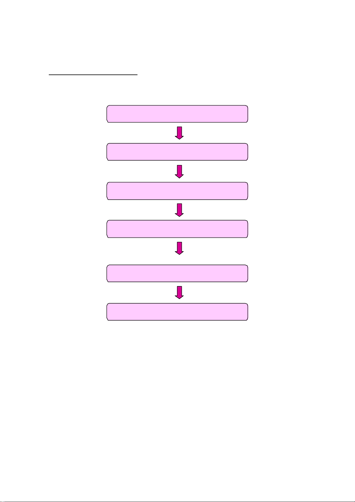
1. Inserting components onto fiber cable
3. Inserting fiber into connector body
2. Preparing fiber cable
4. Processing kevlars
5. Heat curing
6. Assembling crimping sleeve and boot
Page 2
4. Assembly Procedure
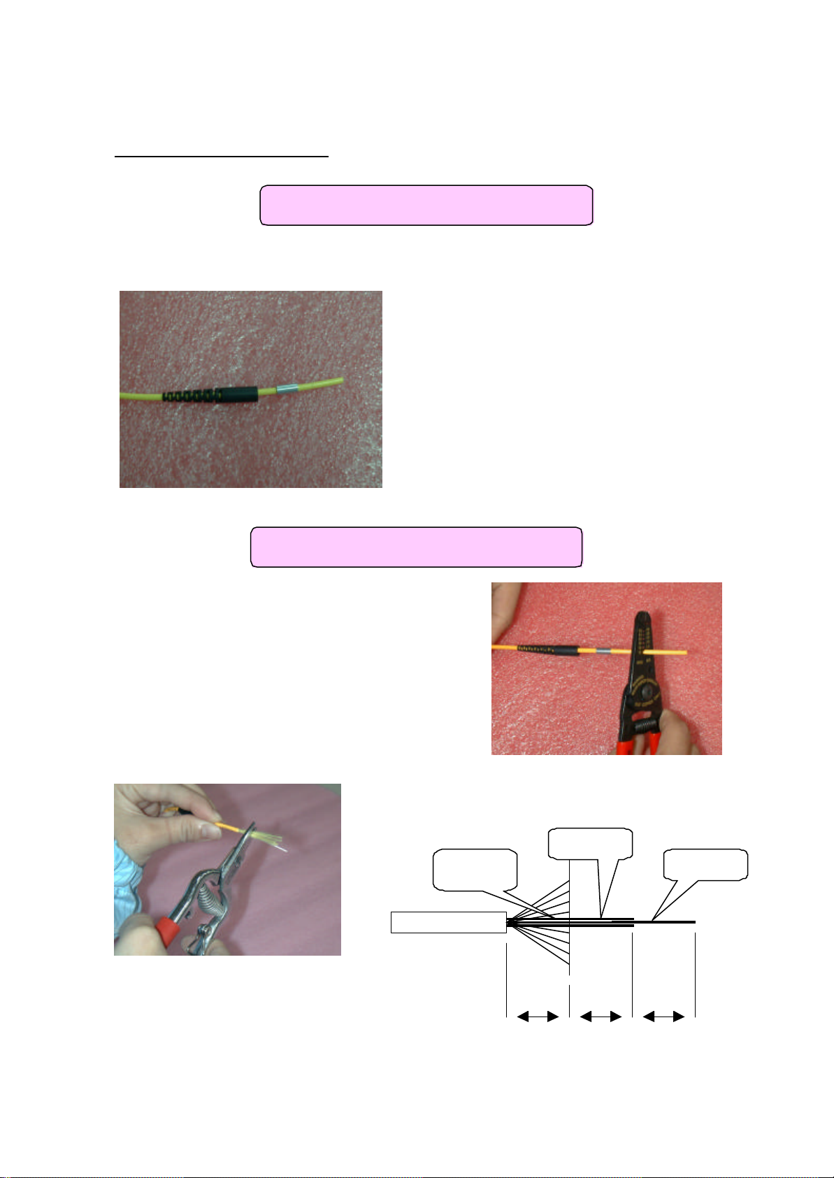
Step 2. Using the PVC stripping tool,
Step 1. Insert (in order) rubber hood and
81116
1. Inserting components onto fiber cable
crimping sleeve onto fiber cable.
2. Preparing fiber cable
strip approximately 35mm of the PVC
layer. (See Figure 1 below)
Step 3. Trim the kevlars with shears
to the length as shown in Figure 1.
Kevlar
900um
Fiber
Figure 1.
Page 3
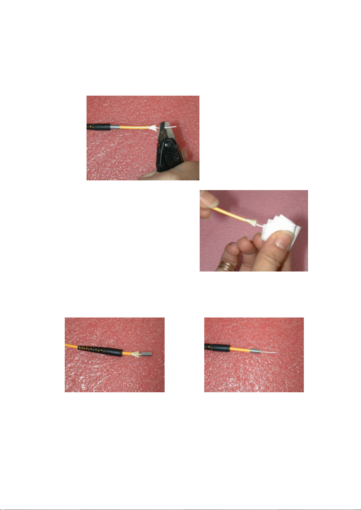
Step 5. Soak a piece of cleaning
Step 4. Strip off 900um PVC
coating according to the required
length as in Figure 1.
paper in alcohol and carefully wipe
off silicon adhering to the fiber with
the paper.
Step 6. Pull the crimping sleeve forward past the ends of the kevlar. Then push the
crimping sleeve back ensuring that it gathers all the kevlar strands and holds them neatly
out of the way.
Page 4
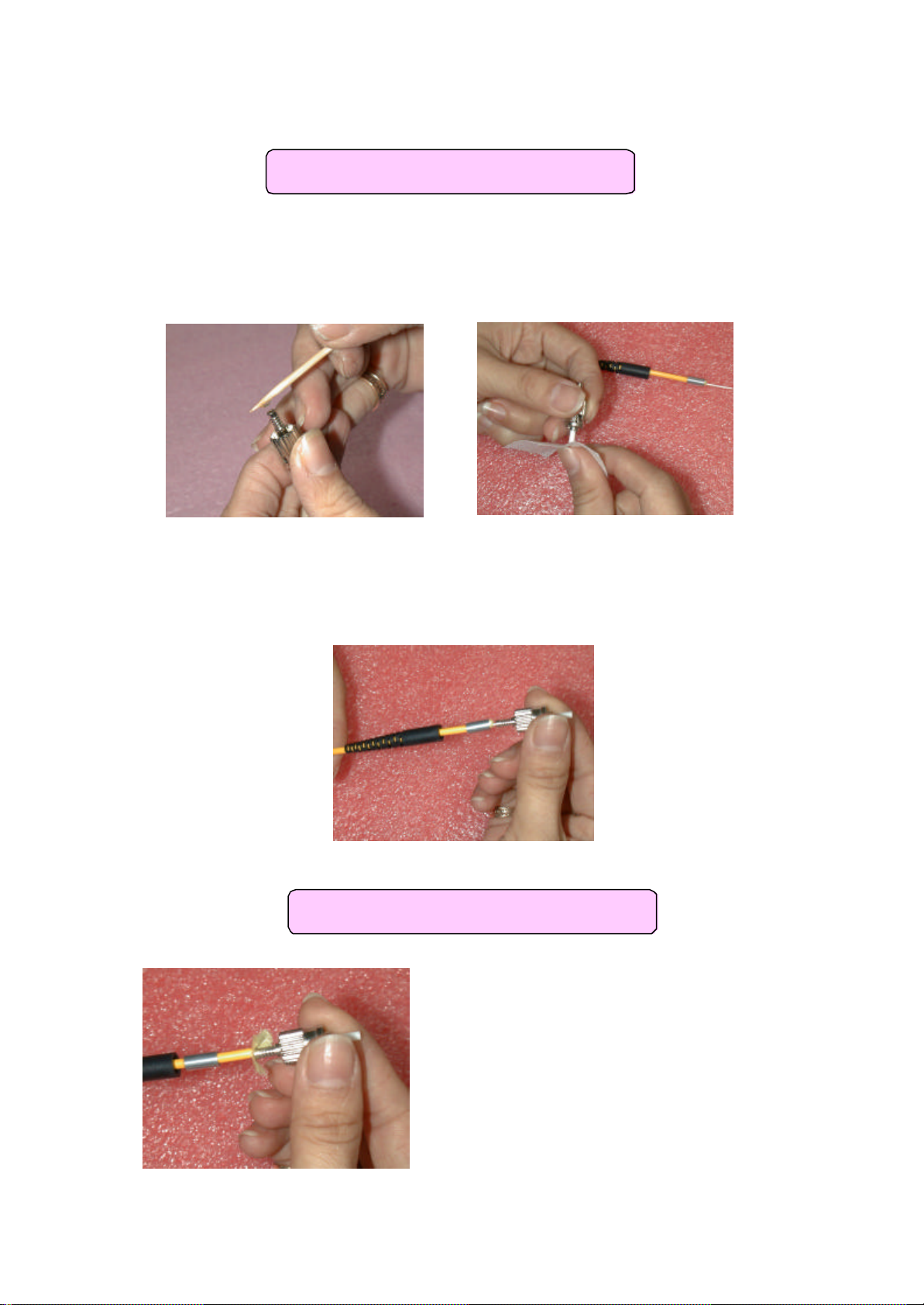
3. Inserting fiber into connector body
Step 9. Gently pull the crimping
Step 7. Drop a small quantity of 353ND epoxy into ST main body until it is about
60% full. A small amount of epoxy may also be applied to the bare fiber. Clean off
any excess epoxy on the main body with cleaning paper and alcohol.
Step 8. Carefully insert the bare fiber, using a pushing and slow twisting motion, through
the main body and ferrule. The fiber should extend out of the other side of the ferrule.
4. Processing kevlars
sleeve backwards releasing the kevlar.
Page 5
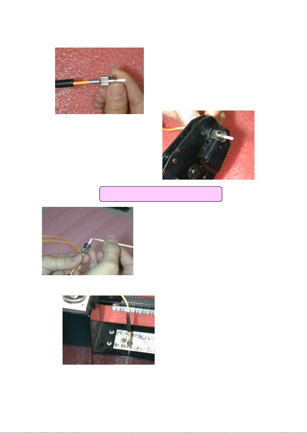
Step 12. Place a small drop of 353ND epoxy
Step 11. Use the crimping tool
Step 10. Push the crimping sleeve back up to
the main body. The kevlar strands should be
held neatly and securely under the crimping
sleeve.
(0.151 diameter slot) to fix the
crimping sleeve, kevlar and main
body.
Step 13. Cure epoxy on heater at a temperature of 120°C for 15 – 20 minutes.
4. Heat curing
on the tip of the ferrule using a toothpick.
Page 6
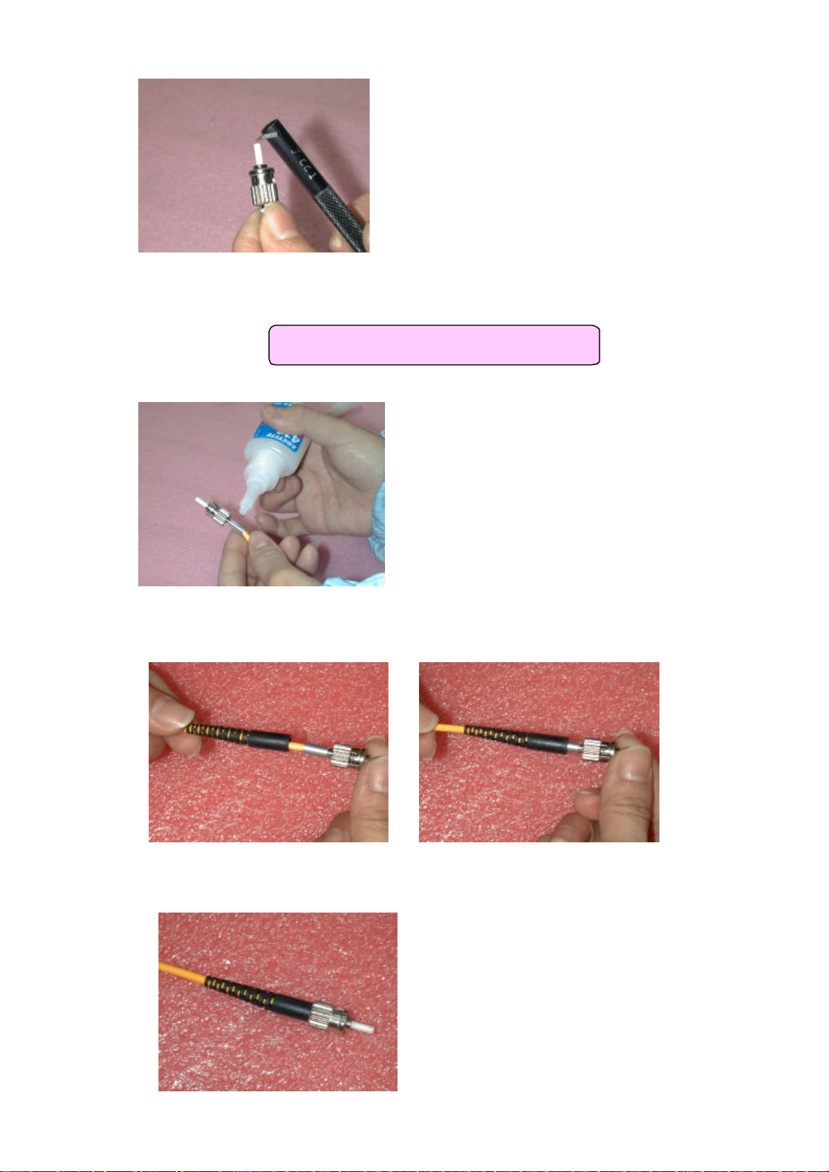
Step 14. Break the fiber that extends out of the
ferrule with a carbide scribe after cooling the
ferrule. Just a light touch is all that is required to
snap the fiber.
6. Assembling crimping sleeve and boot
Step 15. Put a small amount of 411 epoxy on
the crimping sleeve as well as on the PVC tube
1-2cm below the metal part.
Step 16. Using a rotating motion to spread the epoxy evenly around the rubber boot,
push the rubber hood up to combine with the main body.
Step 17. Completed assembly.
 Loading...