

Page 1
MITSUMI
Sync Separator with AFC LVA519
Sync Separator with AFC
Monolithic IC LVA519
Outline
This is a sync separator IC with AFC. Stable operation even in a weak electric field is made possible with the
built-in AFC circuit. A regulator also is built in, providing stable operation relative to power supply and
temperature fluctuations.
Features
1. Supports AFC (horizontal sync signal)
2. AFC OFF function
3. Horizontal and vertical sync signal output pins
4. Power supply voltage 4.7V~5.3V
Package
SIP-9A (LVA519S)
SOP-14A (LVA519F)
Applications
1. TV
2. VCR
3. Other video equipment
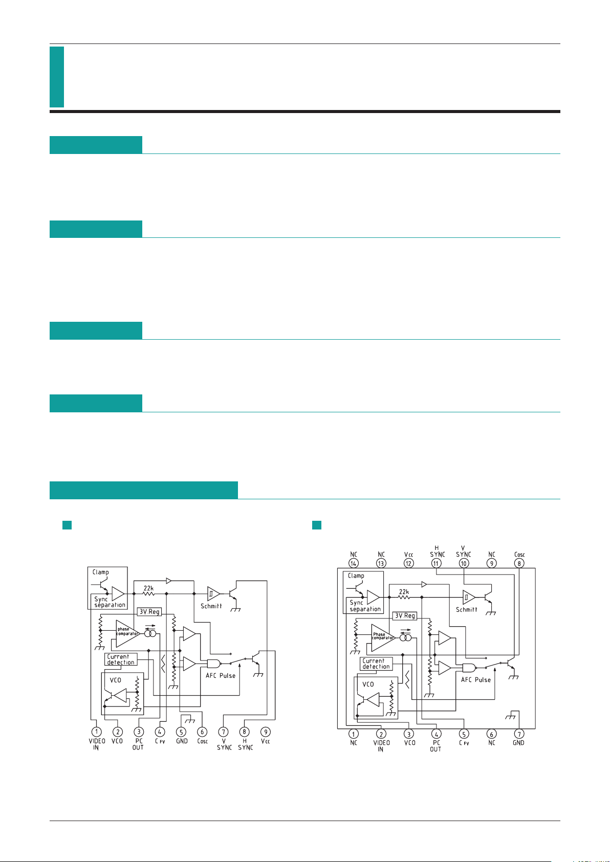
Equivalent Circuit Diagram
SIP-9A SOP-14A
Page 2
MITSUMI
Sync Separator with AFC LVA519
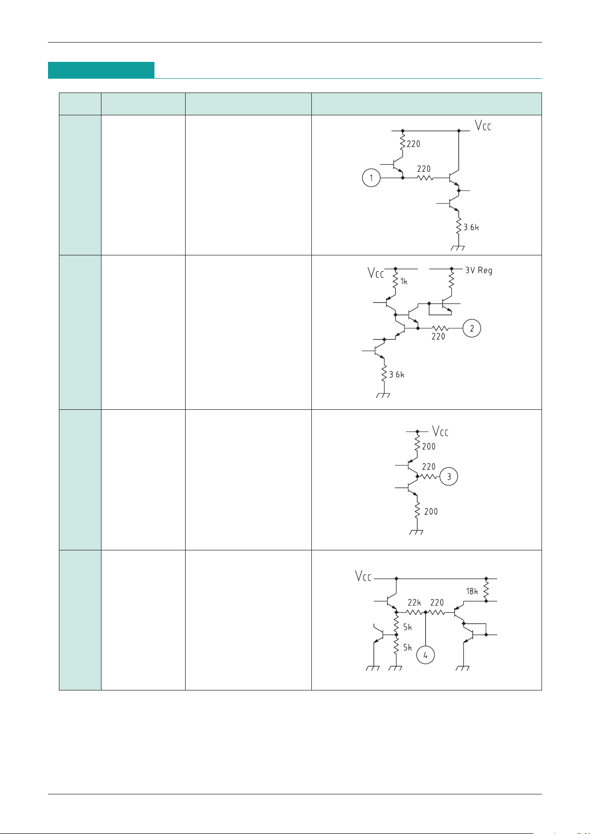
Pin Description
(LVA519S)
Pin no. Pin name Function Internal equivalent circuit diagram
1 VIDEO IN Video signal input
2 VCO Free run frequency setting
3 PC OUT Phase comparison output
4 CFU Integrates composite
signal and inputs to
vertical sync playback
circuit
Page 3
MITSUMI
Sync Separator with AFC LVA519
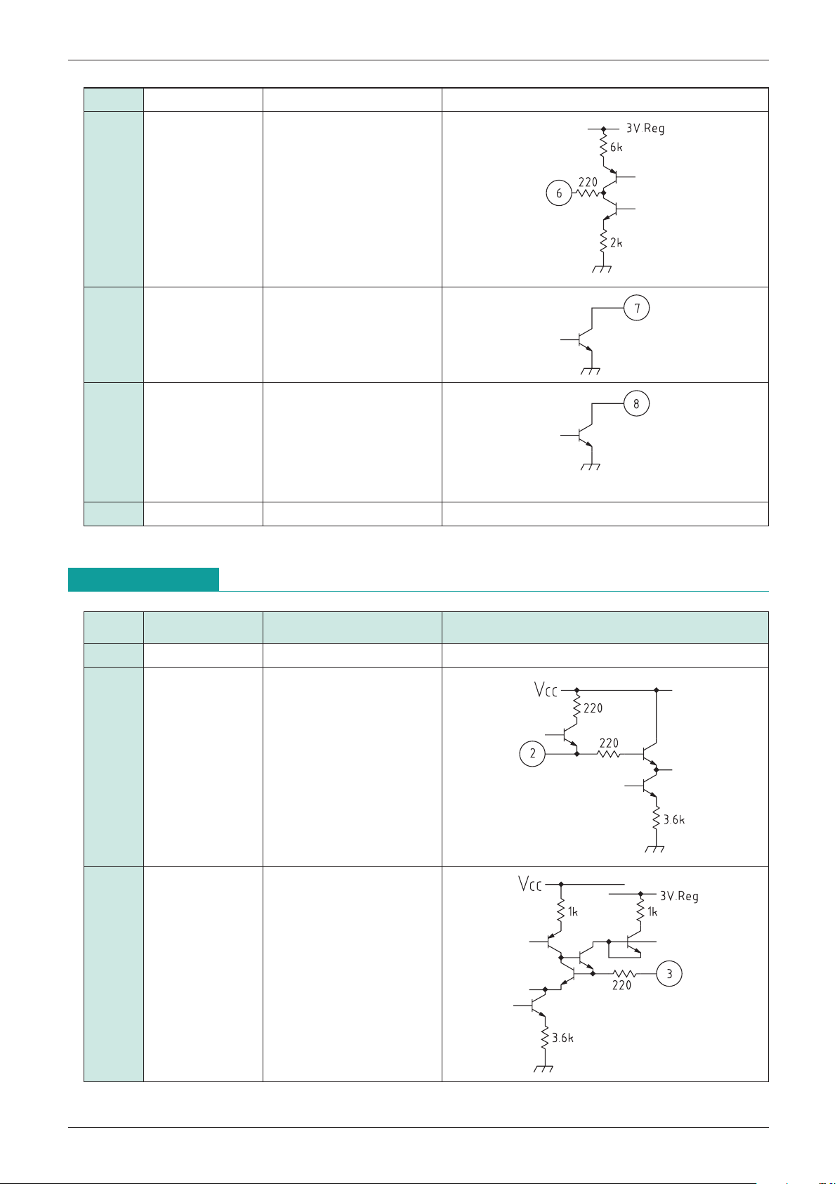
5 GND GND
6 COSC Free run frequency
oscillation circuit
7 VSYNC Vertical sync signal output
8 HSYNC Horizontal sync signal
output
9 VCC Power supply
Pin Description
(LVA519F)
Pin no. Pin name Function Internal equivalent circuit diagram
1 NC
2 VIDEO IN Video signal input
3 VCO Free run frequency setting
Page 4

MITSUMI
Sync Separator with AFC LVA519
4 PC OUT Phase comparison output
5 CFU Integrates composite
signal and inputs to
vertical sync playback
circuit
8 COSC Free run frequency
oscillation circuit
10 VSYNC Vertical sync signal output
11 HSYNC Horizontal sync signal
output
12 VCC Power supply
13 NC
14 NC
9 NC
6 NC
7 GND GND
Page 5

MITSUMI
Sync Separator with AFC LVA519
Absolute Maximum Ratings
(Ta=25°C)
Item Symbol Ratings Units
Storage temperature T
STG
-
40~+125 °C
Operating temperature T
OPR
-
2~+75 °C
Power supply voltage V
CC max. 7 V
Allowable loss Pd
470 (SIP-9A)
350 (SOP-14A)
mW
Recommended Operating Conditions
(Ta=25°C)
Item Symbol Min. Typ. Max. Units
Recommended power supply
V
CC 4.7 5.0 5.3 V
voltage range
Recommended input
V
IN 0.8 2.0 3.2 VP-P
signal voltage
Electrical Characteristics
(Except where noted otherwise, Ta=25°C, VCC=5.0V, VIN=2.0V
P-P
)
Item Symbol Measurement conditions Min. Typ. Max. Units
Consumption current Id Refer to Measuring Circuit 7.0 10 mA
Horizontal sync output (H) V
HH Refer to Measuring Circuit 4.9 5.0 V
Horizontal sync output (L) V
HL Refer to Measuring Circuit 0.2 0.4 V
Vertical sync output (H) V
VH Refer to Measuring Circuit 4.9 5.0 V
Vertical sync output (L) V
VL Refer to Measuring Circuit 0.2 0.4 V
Free-running frequency setting range f
O Refer to Measuring Circuit 14.5 17.0 kHz
Power supply fluctuation of
f
O1 Refer to Measuring Circuit 300 %/V
free-running frequency
Free-running frequency temperature
f
O2 Refer to Measuring Circuit 400
ppm/V
coefficient Capture range
Capture range f
C Refer to Measuring Circuit 1.0 1.3 kHz
Lock range f
L Refer to Measuring Circuit 1.9 2.5 kHz
AFC output delay time td Refer to Measuring Circuit 0.3 0.7 1.1 µS
AFC output pulse width P
W Refer to Measuring Circuit 3.5 5.0 6.5 µS
Schmitt trigger (H) Vth
H Refer to Measuring Circuit 1.9 2.1 2.3 V
threshold (L) Vth
L Refer to Measuring Circuit 1.1 1.3 1.5 V
Sync separation level V
SEPA Refer to Measuring Circuit 80 115 170 mV
AFC off resistance R
AFC Refer to Measuring Circuit 2.7 4.0 6.0 kΩ
Page 6

MITSUMI
Sync Separator with AFC LVA519
Measuring Procedures
(Except where noted otherwise, Ta=25°C, VCC=5.0V, VIN=2.0VP
-
P)
Item
Symbol
Switch state
Measuring Procedures
S1 S2 S3 S4 S5
Consumption current Id B B A A A
Horizontal sync
(H) V
HH
BABBA
output (L) VHL BABBA
Vertical sync
(H) V
VH
BABBA
output (L) VVL BABBA
Free-running frequency
f
O ABBBA
setting range
Power supply fluctuation of
fO1A B B B A
free-running frequency
Free-running frequency
fO2A B B B A
temperature coefficient
Capture range fC B/A A B B A
Lock range f
L B/A A B B A
AFC output delay time td A/B A B B A
AFC output pulse width Pw A/B A B B A
Schmitt trigger
(H) Vt
HH
BABBA
threshold
(L) VtHL
Connect a DC ammeter to VCC pin.
Input standard color bar 2V
P-P.
Measure at TP5
Input standard color bar 2V
P-P.
Measure at TP4.
Adjust VR1 and measure frequency at TP5.
With fo at 15.73kHz, vary Vcc between 4.0V~6.0V
and measure at TP5.
With fo at 15.73kHz, vary temperature between
-
20°C and 80°C and measure at TP5.
Input standard color bar 2V
P-P
and measure at TP1 and TP5. *1
Input standard color bar 2V
P-P
and measure at TP1 and TP5. *1
Input standard color bar 2V
P-P
and measure at TP2 and TP5. *2
Input standard color bar 2V
P-P
and measure at TP5. *2
Measure at TP3 and TP4. *3
Notes:
*
1 Capture range (fc) Vary VR1 between max min and min max with SW1, and for each
lock make SW1 A and measure at TP5.
Data : f
C1 and fC2 smaller value
Lock range (fL) With SW1 at B and locked, vary VR1 and when the lock is released,
make SW1 A and measure at TP5.
Data : f
L1 and fL2 smaller value
fc1 fc2
15.73KHz
fL1 fL2
15.73KHz
Measuring Procedures
(Except where noted otherwise, Ta=25°C, VCC=5.0V, VIN=2.0V
P-P
)
Item
Symbol
Switch state
Measuring Procedures
S1 S2 S3 S4 S5
Sync separation
V
SEPA BABBA
level
AFC switching
R
AFC BABBB
resistance
Raise horizontal sync signal level of input standard
color bar 2V
P-P and measure the level when a signal
is output at TP5.
With Fo at 15.73kHz, vary Iafc, and determine
according to Iafc value when TP5 output signal
switches to a composite signal, and TP6 voltage V6.
R
AFC=V6/IA1
Page 7

MITSUMI
Sync Separator with AFC LVA519
*
2
*
AFC output delay time (td)
Set SW1 at A and adjust TP5 output to 15.73kHz. Then set SW1 to B
and measure td from TP2 and TP5 waveforms. (specified at 50% of
sync signal amplitude)
*
AFC output pulse width (Pw)
Set SW1 at A and adjust TP5 output to 15.73kHz. Then set SW1 to B
and measure Pw from TP5 waveform. (specified at 50% of sync
signal amplitude)
*
3
*
Schmidt trigger threshold
(Vth
H) (VthL)
Measure Vth
H and VthL at TP3 and TP4.
TP4
TP3
V
thH
VthL
Measuring Circuit
SIP-9A
SOP-14A
TP2
TP5
50
50
100
Pw
td
Page 8

MITSUMI
Sync Separator with AFC LVA519
Application Circuits
SIP-9A
SOP-14A
 Loading...