

Page 1

LTC4413-1/LTC4413-2
Dual 2.6A, 2.5V to 5.5V
Fast Ideal Diodes
in 3mm × 3mm DFN
FEATURES
n
2-Channel Ideal Diode OR’ing or Load Sharing
n
Low Loss Replacement for PowerPath™ OR’ing
Diodes
n
Fast Response Replacement for LTC4413
n
Low Forward On-Resistance (140mΩ Max at 3.6V)
n
Low Reverse Leakage Current
n
Low Regulated Forward Voltage (18mV Typ)
n
Overvoltage Protection Sensor with Drive Output for
an External P-Channel MOSFET (LTC4413-2 Only)
n
2.5V to 5.5V Operating Range
n
2.6A Maximum Forward Current
n
Internal Current Limit Protection
n
Internal Thermal Protection
n
Status Output to Indicate if Selected Channel is
Conducting
n
Programmable Channel On/Off
n
Low Profi le (0.75mm) 10-Lead 3mm × 3mm DFN
Package
APPLICATIONS
n
Battery and Wall Adapter Diode OR’ing in Handheld
Products
n
Backup Battery Diode OR’ing
n
Power Switching
n
USB Peripherals
n
Uninterruptable Supplies
DESCRIPTION
The LTC®4413-1 and LTC4413-2 each contain two monolithic ideal diodes, each capable of supplying up to 2.6A
from input voltages between 2.5V and 5.5V. The ideal
diodes use a 100mΩ P-channel MOSFET to independently
connect INA to OUTA and INB to OUTB. During normal
forward operation, the voltage drops across each of
these diodes are regulated to as low as 18mV. Quiescent
current is less than 80μA for diode currents up to 1A. If
either of the output voltages exceeds its respective input
voltage, that MOSFET is turned off and less than 1μA of
reverse current fl ows from OUT to IN. Maximum forward
current in each MOSFET is limited to a constant 2.6A and
internal thermal limiting circuits protect the part during
fault conditions. An internal overvoltage protection sensor
detects when a voltage exceeds the LTC4413-2 absolute
maximum voltage tolerance.
Two active-high control pins independently turn off the two
ideal diodes contained within the LTC4413-1/LTC4413-2.
When the selected channel is reverse biased, or the
LTC4413-1/LTC4413-2 is put into low power standby, the
status signal is pulled low by an 11μA open drain.
The LTC4413-1/LTC4413-2 are housed in a 10-lead 3mm
× 3mm DFN package.
L, LT, LTC, LTM, Linear Technology and the Linear logo are registered trademarks of Linear
Technology Corporation. PowerPath is a trademark of Linear Technology Corporation.
All other trademarks are the property of their respective owners.
TYPICAL APPLICATION
Automatic Switchover from a Battery to a Wall Adapter
FDR8508
WALL
ADAPTER
INPUT
INA
0.1μF
1Ω
10μF
ENBA
GND
BAT
+
STAT IS HIGH WHEN WALL ADAPTER IS
SUPPLYING LOAD CURRENT
OVP IS HIGH WHEN WALL ADAPTER VOLTAGE > 6V
ENBB
INB
IDEAL
LTC4413-2
IDEAL
OUTA
STAT
OVI
OVP
OUTB
V
CC
441312 TA01a
470k
4.7μF
STAT
OVP
TO LOAD
Power Loss vs Load
700
600
500
400
300
1N5817
POWER LOSS (mW)
200
100
0
0
500 1000
LTC4413-1
2000 3000
1500 2500
LOAD (mA)
441312 TA01b
441312fd
1
Page 2

LTC4413-1/LTC4413-2
(
(
ABSOLUTE MAXIMUM RATINGS
INA, INB, OUTA, OUTB, STAT,
ENBA, ENBB Voltage .................................... –0.3V to 6V
OVI, OVP Voltage ....................................... –0.3V to 13V
(Note 1)
Storage Temperature Range ..................–65°C to 125°C
Continuous Power Dissipation ..........................1500mW
(Derate 25mW/°C Above 70°C)
Operating Temperature Range .................–40°C to 85°C
PIN CONFIGURATION
LTC4413-1 LTC4413-2
TOP VIEW
10
INA
1
ENBA
2
11
3
GND
4
ENBB
5
INB
DD PACKAGE
3mm × 3mm) PLASTIC DFN
10-LEAD
T
= 125°C, θJA = 43°C/W
EXPOSED PAD (PIN 11) IS GND, MUST BE SOLDERED TO PCB
JMAX
OUTA
9
STAT
NC
8
7
NC
6
OUTB
TOP VIEW
10
INA
1
ENBA
2
11
3
GND
4
ENBB
5
INB
DD PACKAGE
3mm × 3mm) PLASTIC DFN
10-LEAD
T
= 125°C, θJA = 43°C/W
EXPOSED PAD (PIN 11) IS GND, MUST BE SOLDERED TO PCB
JMAX
OUTA
9
STAT
OVI
8
7
OVP
6
OUTB
ORDER INFORMATION
LEAD FREE FINISH TAPE AND REEL PART MARKING PACKAGE DESCRIPTION TEMPERATURE RANGE
LTC4413EDD-1#PBF LTC4413EDD-1#TRPBF LCPP
LTC4413EDD-2#PBF LTC4413EDD-2#TRPBF LCPQ
10-Lead (3mm × 3mm) Plastic DFN
10-Lead (3mm × 3mm) Plastic DFN
LEAD BASED FINISH TAPE AND REEL PART MARKING PACKAGE DESCRIPTION TEMPERATURE RANGE
LTC4413EDD-1 LTC4413EDD-1#TR LCPP
LTC4413EDD-2 LTC4413EDD-2#TR LCPQ
10-Lead (3mm × 3mm) Plastic DFN
10-Lead (3mm × 3mm) Plastic DFN
Consult LTC Marketing for parts specifi ed with wider operating temperature ranges.
For more information on lead free part marking, go to: http://www.linear.com/leadfree/
For more information on tape and reel specifi cations, go to: http://www.linear.com/tapeandreel/
ELECTRICAL CHARACTERISTICS
The l denotes the specifi cations which apply over the full operating
temperature range, otherwise specifi cations are at TA = 25°C. (Notes 2, 6)
SYMBOL PARAMETER CONDITIONS MIN TYP MAX UNITS
, V
V
IN
Operating Supply Range for Channel A or B VIN and/or V
OUT
Proper Operation
UVLO UVLO Turn-On Rising Threshold Max (V
UVLO Turn-Off Falling Threshold Max (V
I
QF
I
QRIN
I
QRGND
Quiescent Current in Forward Regulation,
Measured via GND
Current Drawn from or Sourced into IN
When V
is Greater than V
OUT
IN
Quiescent Current While in Reverse
Turn-Off, Measured via GND
V
= 3.6V, I
INA
I
= 0mA (Note 3)
INB
VIN = 3.6V, V
V
= V
INA
V
STAT
INA
INA
INB
= 0V
Must be in This Range for
OUT
, V
, V
, V
, V
= V
OUTB
OUTB
OUTA
)
)
INB
INB
OUTA
, V
, V
INB
OUTA
= 100mA, V
INA
= 5.5V (Note 6)
OUT
= 0V, V
OUTB
= 0V,
= 5.5V,
l
2.5 5.5 V
l
l
1.7 V
l
l
–1 2.5 4.5 μA
–40°C to 85°C
–40°C to 85°C
–40°C to 85°C
–40°C to 85°C
2.45 V
40 58 μA
28 36 μA
441312fd
2
Page 3

LTC4413-1/LTC4413-2
ELECTRICAL CHARACTERISTICS
The l denotes the specifi cations which apply over the full operating
temperature range, otherwise specifi cations are at T
SYMBOL PARAMETER CONDITIONS MIN TYP MAX UNITS
I
QROUTB
I
QOFF
V
RTO
V
FWD
R
FWD
R
ON
t
ON
t
OFF
Short-Circuit Response
I
OC
I
QOC
STAT Output
I
SOFF
I
SON
t
S(ON)
t
S(OFF)
ENB Inputs
V
ENBIH
V
ENBIL
V
ENBHYST
I
ENB
OVI Input (LTC4413-2 Only)
V
OVIH
V
OVIL
V
OVID
I
OVI
Quiescent Current While in Reverse
Turn-Off. Current Drawn from V
OUTA
When
OUTB Supplies Chip Power
Quiescent Current with Both ENBA and
ENBB High
Reverse Turn-Off Voltage (V
Forward Voltage Drop (VIN – V
at I
= –1mA
OUT
On-Resistance, R
Regulation
FWD
– VIN)V
OUT
)
OUT
(Measured as ΔV/ΔI)
On-Resistance, RON Regulation
(Measured as V/I at I
= 1A)
IN
PowerPath Turn-On Time VIN = 3.6V, from ENB Falling to I
PowerPath Turn-Off Time VIN = 3.6V, from ENB Rising with IIN = 100mA
Current Limit V
Quiescent Current While in Overcurrent
Operation
STAT Off Current Shut Down
STAT Sink Current VIN > V
STAT Pin Current Turn-On Time VIN = 3.6V, from ENB Falling 1.8 μs
STAT Pin Current Turn-Off Time VIN = 3.6V, from ENB Rising 0.8 μs
ENB Inputs Rising Threshold Voltage V
ENB Inputs Falling Threshold Voltage V
ENB Input Hysteresis V
ENB Inputs Pull-Down Current V
OVI Input Rising Threshold Voltage V
OVI Input Falling Threshold Voltage V
OVI-OVP Voltage Drop V
OVI Bias Current V
= 25°C. (Notes 2, 6)
A
= V
V
INA
V
INA
IN
V
IN
VIN = 3.6V, I
V
IN
= 0V, V
INB
= V
= 3.6V, V
INB
= 3.6V
= 3.6V
OUT
= 3.6V, IIN = 1A (Note 5) 140 200 mΩ
OUTA
ENBA
= 3.6V, V
= V
ENBB
OUTB
= 1V
= 5.5V
= –100mA to –500mA (Note 5) 100 140 mΩ
Ramp
OUT
l
l
l
–5 10 mV
l
3.5 6.5 μA
28 38 μA
18 24 mV
11 μs
Starting
2μs
Falling to 0mA
= 3.6V (Note 5) 1.8 A
INA OR B
V
= 3.6V, I
INA OR B
, V
OUT
Rising
ENB
Falling
ENB
= (V
ENBHYST
< VIN = 3.6V, V
OUT
Rising 5.9 6.2 V
OVI
Falling 5.4 5.6 V
OVI
= 8V, No Load at OVP 100 mV
OVI
= 8V 80 μA
OVI
= 1.8A (Note 5) 100 130 μA
OUT
l
–1 0 1 μA
< VIL, TJ < 135°C, I
CTL
– V
ENBIH
ENB
ENBIL
< V
IL
< I
OUT
)90mV
MAX
l
71115 μA
l
l
400 460 mV
l
234 μA
540 600 mV
Note 1: Stresses beyond those listed under Absolute Maximum Ratings
may cause permanent damage to the device. Exposure to any Absolute
Maximum Rating condition for extended periods may affect device
reliability and lifetime.
Note 2: The LTC4413-1/LTC4413-2 are guaranteed to meet performance
specifi cations from 0°C to 85°C. Specifi cations over the –40°C to 85°C
operating temperature range are assured by design, characterization and
correlation with statistical process controls.
Note 3: Quiescent current increases with diode current: refer to plot of
I
vs I
OUT
.
QF
Note 4: This IC includes overtemperature protection that is intended
to protect the device during momentary overload conditions.
Overtemperature protection will become active at a junction temperature
greater than the maximum operating temperature. Continuous operation
above the specifi ed maximum operating junction temperature may impair
device reliability.
Note 5: Specifi cation is guaranteed by correlation to wafer-level
measurements.
Note 6: Unless otherwise specifi ed, current into a pin is positive and
current out of a pin is negative. All voltages referenced to GND.
441312fd
3
Page 4
LTC4413-1/LTC4413-2
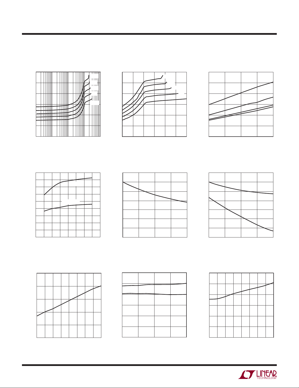
TYPICAL PERFORMANCE CHARACTERISTICS
IQF vs I
120
100
80
(μA)
60
QF
I
40
20
0
1 100 1000 10000
IQF vs V
90
80
70
60
50
(μA)
QF
I
40
30
20
10
0
2.5
2
(Log) IQF vs I
LOAD
10
LOAD (mA)
IN
IQF = 1A
IQF = 100mA
4
VIN (V)
4.5
5
3
3.5
120°C
80°C
40°C
0°C
–40°C
441312 G01
5.5
441312 G04
(Linear) IQF vs Temperature
120
100
(μA)
QF
I
80
60
40
20
0
LOAD
120°C
80°C
40°C
0°C
–40°C
0
1000 1500 2000
500
LOAD (mA)
2500 3000
441312 G02
120
100
(μA)
QF
I
1A
80
60
40
20
0
–40
0 40 80 120
TEMPERATURE (°C)
500mA
100mA
1mA
441312 G03
IOC vs Temperature UVLO Thresholds vs Temperature
3500
3000
2500
2000
(mA)
OC
I
1500
1000
500
6
0
–40
0 40 120
TEMPERATURE (°C)
80
441312 G05
2.20
2.15
2.10
2.05
2.00
1.95
UVLO THRESHOLDS (V)
1.90
1.85
–40
0 40 120
TEMPERATURE (°C)
RISING
FALLING
80
441312 G06
UVLO Hysteresis vs Temperature
250
200
150
100
UVLO HYSTERESIS (mV)
50
0
–40
–20 0
20 60 120
TEMPERATURE (°C)
4
ENB Thresholds vs Temperature ENB Hysteresis vs Temperature
600
500
400
300
200
ENBIH/ENBIL (mV)
100
0
40
80 100
441312 G07
–40
0 40 80 120
TEMPERATURE (°C)
ENBIH
ENBIL
441312 G08
120
100
80
60
40
ENB HYSETERSIS (mV)
20
0
–40
040
–20 20
TEMPERATURE (°C)
80
60
100
441312 G09
441312fd
120
Page 5

TYPICAL PERFORMANCE CHARACTERISTICS
0
R
FWD
80
78
76
74
72
70
500mA (mΩ)
68
FWD
R
66
64
62
60
2
2.5 3.5
V
FWD
250
200
150
(mV)
FWD
V
100
50
vs VIN and I
3
vs I
120°C
80°C
40°C
0°C
–40°C
LOAD
(Log)
4
VIN (V)
LOAD
4.5
= 500mA
5.5
5
441312 G10
V
and R
FWD
500
400
300
(mΩ)
FWD
R
200
100
0
6
0
120
100
(mΩ)
FWD
R
120°C
80°C
40°C
0°C
–40°C
500
R
FWD
80
60
40
20
vs I
FWD
1000 1500 2000
LOAD
LOAD (mA)
vs Temperature
100mA
1A
(Linear)
V
FWD
R
FWD
2500 3000
441312 G11
500mA
LTC4413-1/LTC4413-2
R
250
200
150
100
50
0
V
FWD
(mV)
600
500
400
(mΩ)
300
FWD
R
200
100
0
1
0.01
(μA)
LEAK
I
0.001
0.0001
FWD
1
0.1
and V
R
FWD
I
LEAK
V
REVERSE
vs I
FWD
10 100 1000 10000
LOAD (mA)
LOAD
120°C
80°C
40°C
0°C
–40°C
V
(Log)
FWD
441312 G12
vs Temperature at
= 5.5V
5.5V
3.6V
300
250
200
150
100
50
0
V
FWD
(mV)
0
1 100 1000 10000
100
10
1
0.1
(μA)
0.01
LEAK
I
0.001
0.0001
0.00001
0
I
LEAK
10
LOAD (mA)
vs V
REVERSE
120°C
80°C
40°C
0°C
–40°C
241356
V
(V)
REVERSE
0
–40
441312 G13
0 40 80 120
TEMPERATURE (°C)
441312 G14
Response to 800mA Load Step
in <16μs
CH1 = IN 100mV/DIV
CH2 OUT
100mV/DIV
CH4 I
OUT
200mV/DIV
4μs/DIV
441312 G16
441312 G17
0.00001
–40 40 80
0–20 60 10020
TEMPERATURE (°C)
ENB Turn-On, 30μs to Turn On
with 180mA Load
CH1 IN 1V/DIV
CH3 ENB
1V/DIV
CH4 I
OUT
200mV/DIV
10μs/DIV
12
441312 G15
CH2 OUT
1V/DIV
441312 G18
441312fd
5
Page 6

LTC4413-1/LTC4413-2
0
TYPICAL PERFORMANCE CHARACTERISTICS
ENB Turn-Off, 2μs to Disconnect
IN from 180mA Load
CH2 OUT
1V/DIV
CH3 ENB
1V/DIV
4μs/DIV
CH1 IN 1V/DIV
CH4 I
IN
100mV/DIV
441312 G19
Effi ciency vs Load Current Power Loss vs Load Current
100
99
98
97
96
95
94
EFFICIENCY (%)
93
92
91
90
120°C
80°C
40°C
0°C
–40°C
1 100 1000 10000
10
LOAD (mA)
441312 G20
1000
100
10
POWER LOSS (mW)
1
0
120°C
80°C
40°C
0°C
–40°C
1
100 10 1000 1000
LOAD (mA)
441312 G21
Overvoltage Thresholds
vs Temperature (LTC4413-2 Only)
6.4
6.2
6.0
5.8
5.6
OVPIH/OVPIL (V)
5.4
5.2
5.0
–40
OVP RISING
OVP FALLING
0 40 120
TEMPERATURE (°C)
OVI-OVP Voltage Drop
vs OVI Voltage (LTC4413-2 Only)
6
TA = 25°C
5
4
3
OVP (V)
2
1
0
0
24
812
610
OVI (V)
Overvoltage Hysteresis
vs Temperature (LTC4413-2 Only)
400
350
300
250
200
150
OVP HYSTERESIS (mV)
100
50
0
80
441312 G22
–40
0
40
TEMPERATURE (°C)
120
80
441312 G23
IQ OVI vs Temperature
(LTC4413-2 Only)
180
441312 G25
160
140
120
100
OVI (μA)
80
Q
I
60
40
20
0
–40
IQ OVI = 13V
IQ OVI = 6.5V
0
40
TEMPERATURE (°C)
80
120
441312 G26
OVI Current vs Voltage
(LTC4413-2 Only)
140
TA = 25°C
120
100
80
(μA)
OVI
I
60
40
20
0
0
24
OVI-OVP vs Temperature
(LTC4413-2 Only)
160
140
120
100
80
OVI-OVP (mV)
60
40
20
0
–40
–20
0
V
OHOVP
20
TEMPERATURE (°C)
812
610
V
(V)
OVI
V
OHOVP
= 6.5V
40
60
= 13V
441312 G24
80
100
441312 G27
120
6
441312fd
Page 7

PIN FUNCTIONS
LTC4413-1/LTC4413-2
INA (Pin 1): Primary Ideal Diode Anode and Positive Power
Supply for LTC4413-1/LTC4413-2. Bypass INA with a ceramic capacitor of at least 1μF. (Series 1Ω snub resistors
and higher valued capacitances are recommended when
large inductances are in series with this input.) This pin
can be grounded when not used. Limit slew rate on this
pin to less than 2.5V/μs.
ENBA (Pin 2): Enable Low for Diode A. Pull this pin high
to shut down this power path. Tie to GND to enable.
Refer to Table 1 for mode control functionality. This pin
can be left fl oating, a weak (3.5μA) pull-down internal to
LTC4413-1/LTC4413-2 is included.
GND (Pin 3): Power Ground for the IC.
ENBB (Pin 4): Enable Low for Diode B. Pull this pin high
to shut down this power path. Tie to GND to enable.
Refer to Table 1 for mode control functionality. This pin
can be left fl oating, a weak (3.5μA) pull-down internal to
LTC4413-1/LTC4413-2 is included.
INB (Pin 5): Secondary Ideal Diode Anode and Positive
Power Supply for LTC4413-1/LTC4413-2. Bypass INB with a
ceramic capacitor of at least 1μF. (Series 1Ω snub resistors
and higher valued capacitances are recommended when
large inductances are in series with this input.) This pin
can be grounded when not used. Limit slew rate on this
pin to less than 2.5V/μs.
OVP (Pin 7, LTC4413-2 Only): Drive Output for an External OVP Switch PMOS Transistor (To Inhibit Overvoltage
Wall Adapter Voltages from Damaging Device.) During
overvoltage conditions, this output will remain high so
long as an overvoltage condition persists. This pin must
be left fl oating when not in use.
OVI (Pin 8, LTC4413-2 Only): Sense Input for Overvoltage
Protection Block. This pin can be left fl oating or grounded
when not used.
STAT (Pin 9): Status Condition Indicator. Weak (11μA)
pull-down current output. When terminated, high indicates
diode conducting. Refer to Table 2 for the operation of this
pin. This pin can also be left fl oating or grounded.
OUTA (Pin 10): Primary Ideal Diode Cathode and Output
of the LTC4413-1/LTC4413-2. Bypass OUTA with a high
(1mΩ min) ESR ceramic capacitor of at least 4.7μF. This
pin must be left fl oating when not in use. Limit slew rate
on this pin to less than 2.5V/μs.
Exposed Pad (Pin 11): Signal Ground. This pin must be
soldered to PCB ground to provide both electrical contact
to ground and good thermal contact to PCB.
OUTB (Pin 6): Secondary Ideal Diode Cathode and Output
of the LTC4413-1/LTC4413-2. Bypass OUTB with a high
(1mΩ min) ESR ceramic capacitor of at least 4.7μF. This
pin must be left fl oating when not in use. Limit slew rate
on this pin to less than 2.5V/μs.
441312fd
7
Page 8

LTC4413-1/LTC4413-2
BLOCK DIAGRAM
INA
1 10
ENA
ENB
–
+
–
+
–
+
V
OFF
AENA
–
+
–
+
–
+
V
OFF
BENA
PA
UVLO
ENA
V
GATEA
A
+
–
PB
V
GATEB
B
+
–
ENB
OUTA (MAX)
OUTB (MAX)
OVER TEMP
OVER TEMP
STB
LTC4413-2 ONLY
OVERVOLTAGE PROTECTION
+
–
6V
OVER CURRENT
–
0.5V
3μA
OVER CURRENT
0.5V
3μA
+
–
+
ENBA
2
GND
3
INB
5 6
ENBB
4
OUTA
AENA
BENA
STAT
11μA
OUTB
OVI
OVP
9
8
7
8
441312 BD
441312fd
Page 9

OPERATION
LTC4413-1/LTC4413-2
The LTC4413-1/LTC4413-2 are described with the aid of the
Block Diagram. Operation begins when the power source at
or V
V
INA
rises above the undervoltage lockout (UVLO)
INB
voltage of 2.4V and the corresponding control pin ENBA or
ENBB is low. If only the voltage at the V
the internal power source (V
) is supplied from the V
DD
pin is present,
INA
INA
pin. The amplifi er (A) pulls a current proportional to the
difference between V
INA
and V
from the gate (V
OUTA
GATEA
)
of the internal PFET (PA), driving this gate voltage below
. This turns on PA. As V
V
INA
voltage drop (V
regulates V
FWD
to maintain the small forward voltage
GATEA
) of 15mV below V
pulls up to a forward
OUTA
, the LTC4413
INA
drop. The system is now in forward regulation and the
load at V
is powered from the supply at V
OUTA
load current varies, V
is controlled to maintain V
GATEA
. As the
INA
FWD
until the load current exceeds the transistor’s (PA) ability
to deliver the current as V
point, the PFET behaves as a fi xed resistor, R
approaches GND. At this
GATEA
ON
, whereby
the forward voltage increases slightly with increased load
current. As the magnitude of I
that I
> IOC) the LTC4413-1/LTC4413-2 fi xes the load
LOAD
current to the constant value I
The characteristics for parameters R
are specifi ed with the aid of Figure 1, illustrating the
I
OC
increases further, (such
OUT
to protect the device.
OC
, RON, V
FWD
FWD
and
LTC4413-1/LTC4413-2 forward voltage drop versus that
of a Schottky.
If another supply is provided at V
, the LTC4413-1/
INB
LTC4413-2 likewise regulate the gate voltage on PB to
maintain the output voltage, V
voltage V
voltage at V
. If this alternate supply, V
INB
, the LTC4413-1/LTC4413-2 selects this
INA
input voltage as the internal supply (V
, just below the input
OUTB
, exceeds the
INB
). This second
DD
ideal diode operates independently of the fi rst ideal diode
function.
When an alternate power source is connected to the load
OUTA
(or V
at V
increased voltage at V
voltage V
V
OUTA
to V
GATEA
is higher than V
, turning off PA. The internal power source for the
DD
LTC4413-1/LTC4413-2 (V
from the V
V
OUTB
OUTA
). The system is now in the reverse turn-off mode.
), the LTC4413-1/LTC4413-2 sense the
OUTB
, and amplifi er A increases the
OUTA
, reducing the current through PA. When
+ V
INA
DD
pin, only if V
RTO
, V
will be pulled up
GATEA
) then diverts to draw current
is larger than V
OUTA
INB
(or
Power to the load is being delivered from an alternate
supply, and only a small current (I
sourced to V
to sense the potential at V
INA
) is drawn from or
LEAK
.
INA
When the selected channel of the LTC4413-1/LTC4413-2
is in reverse turn-off mode or both channels are disabled,
the STAT pin sinks 11μA of current (I
) if connected.
SON
Channel selection is accomplished using the two ENB
pins, ENBA and ENBB. When the ENBA input is asserted
(high), PA has its gate voltage pulled to V
, turning off
DD
PA. A 3.5μA pull-down current on the ENB pins ensures
a low level at these inputs if left fl oating.
I
OC
LTC4413-1
LTC4413-2
SLOPE: 1/R
I
FWD
CURRENT (A)
0
0
Figure 1. The LTC4413 vs the 1N5817
SLOPE: 1/R
V
FWD
FORWARD VOLTAGE (V)
ON
1N5817
FWD
441312 F01
441312fd
9
Page 10

LTC4413-1/LTC4413-2
OPERATION
Overcurrent and Short-Circuit Protection
During an overcurrent condition, the output voltage droops
as the load current exceeds the amount of current that
the LTC4413-1/LTC4413-2 can supply. At the time when
an overcurrent condition is fi rst detected, the LTC4413-1/
LTC4413-2 take some time to detect this condition before
reducing the current to I
output is shorted, until TOC, the current may exceed I
. For short durations after the
OC
OC
.
The magnitude of this peak short-circuit current can be
large depending on the load current immediately before
the short-circuit occurs. During overcurrent operation, the
power consumption of the LTC4413-1/LTC4413-2 is large,
and is likely to cause an overtemperature condition as the
internal die temperature exceeds the thermal shutdown
temperature.
Overtemperature Protection
The overtemperature condition is detected when the
internal die temperature increases beyond 150°C. An
overtemperature condition will cause the gate amplifi ers
(A and B) as well as the two P-channel MOSFETs (PA
and PB) to shut off. When the internal die temperature
cools to below 140°C, the amplifi ers turn on and the
LTC4413-1/LTC4413-2 reverts to normal operation. Note
that prolonged operation under overtemperature conditions degrades reliability.
Overvoltage Protection (LTC4413-2 Only)
An overvoltage condition is detected whenever the
overvoltage input (OVI) pin is pulled above 6V. The condition persists until the OVI voltage falls below 5.6V. The
overvoltage protection (OVP) output is low unless an
overvoltage condition is detected. If an overvoltage condition is present, the OVP output is pulled up to the voltage
applied to the OVI input. This output signal can be used to
enable or disable an external PFET that is placed between
the input that is the source of the excessive voltage and
the input to the LTC4413-2, thus eliminating the potential
damage that may occur to the LTC4413-2 if its input voltage exceeds the absolute maximum voltage of 6V. See
the Applications Information section
Dual Battery Load
Sharing with Automatic Switchover to a Wall Adapter with
Overvoltage Protection
for more information on using the
overvoltage protection function within the LTC4413-2.
Channel Selection and Status Output
Two active-high control pins independently turn off the two
ideal diodes contained within the LTC4413-1/LTC4413-2,
controlling the operation mode as described by Table 1.
When the selected channel is reverse biased, or the
LTC4413-1/LTC4413-2 is put into low power standby, the
status signal indicates this condition with a low voltage.
Table 1. Mode Control
ENB1 ENB2 STATE
Low Low Diode’OR NB: The Two Outputs are not Connected
Low High Diode A = ENABLED, Diode B = DISABLED
High Low Diode A = DISABLED, Diode B = ENABLED
High High All Off (Low Power Standby)
Internal to the Device
The function of the STAT pin depends on the mode that
has been selected. Table 2 describes the STAT pin output
current, as a function of the mode selected as well as the
conduction state of the two diodes.
Table 2. STAT Output Pin Function
ENB1 ENB2 CONDITIONS STAT
Low Low Diode A Forward Bias,
Diode B Forward Bias
Diode A Forward Bias,
Diode B Reverse Bias
Diode A Reverse Bias,
Diode B Forward Bias
Diode A Reverse Bias,
Diode B Reverse Bias
Low High Diode A Forward Bias,
Diode B Disabled
Diode A Reverse Bias,
Diode B Disabled
High Low Diode A Disabled,
Diode B Forward Bias
Diode A Disabled,
Diode B Reverse Bias
High High Diode A Disabled,
Diode B Disabled
I
I
I
I
I
I
I
I
I
SNK
SNK
SNK
SNK
SNK
SNK
SNK
SNK
SNK
= 0μA
= 0μA
= 11μA
= 11μA
= 0μA
= 11μA
= 0μA
= 11μA
= 11μA
10
441312fd
Page 11

APPLICATIONS INFORMATION
LTC4413-1/LTC4413-2
Introduction
The LTC4413-1/LTC4413-2 are intended for power control
applications that include low loss diode OR’ing, fully automatic switchover from a primary to an auxiliary source of
power, microcontroller controlled switchover from a primary to an auxiliary source of power, load sharing between
two or more batteries, charging of multiple batteries from
a single charger and high side power switching.
Dual Battery Load Sharing with Automatic Switchover
to a Wall Adapter with Overvoltage Protection
(LTC4413-2 Only)
An application circuit for dual battery load sharing with
automatic switchover of load from batteries to a wall
adapter is shown in Figure 2. When the wall adapter is not
present, whichever battery has the higher voltage provides
the load current until it has discharged to the voltage of the
other battery. The load is shared between the two batteries according to the capacity of each battery. The higher
capacity battery provides proportionally higher current to
the load. When a wall adapter input is applied, the output
voltage rises as the body diode in MP2 conducts. When
the output voltage is larger than the battery voltages, the
LTC4413 turns off and very little load current is drawn
from the batteries. At this time, the STAT pin pulls down
MP1
IRLML6402
MP2
IRLML6402
the gate voltage of MP2, causing it to conduct. This status
signal can be used to provide information as to whether
the wall adapter (or BATB) is supplying the load current.
If the wall adapter voltage exceeds the OVI trip threshold
) then the wall adapter is disconnected via the
(V
OVIH
external PFET, MP1. The OVI voltage can be monitored
(through a voltage divider if necessary) to determine if
an overvoltage condition is present.
Capacitor C2 is required to dynamically pull up on the
gate of PFET MP1 if a fast edge occurs at the wall adapter
input during a hot plug. In the event that capacitor C2 (or
the gate-to-source of MP1) is precharged below the OVI
rising threshold. When a high voltage spike occurs, the
OVP output cannot guarantee turning off MP1 before the
load voltage exceeds the absolute maximum voltage for
the LTC4413-2. This may occur in the event that the wall
adapter suddenly steps from 5.5V to a much higher value.
In this case, a Zener diode is recommended to keep the
output voltage to a safe level.
Automatic PowerPath Control
Figure 3 illustrates an application circuit for microcontroller monitoring and control of two power sources. The
microcontroller’s analog inputs (perhaps with the aid of
a resistor voltage divider) monitor each supply input and
the LTC4413-1 status, and then commands the LTC4413-1
through the two ENBA/ENBB control inputs.
WALL
ADAPTER
INPUT
JACK
BATA
+
BATB
+
C1
0.10μF
R1
1Ω
IDEAL
LTC4413-2
IDEAL
OUTA
STAT
OVI
OVP
OUTB
INA
1
2
ENBA
3
GND
4
ENBB
INB
5
C2
10nF
OPTIONAL
6.2V
10
9
8
7
6
DFLZ6V2-7
C
OUT
4.7μF
10nF
TO LOAD
R
STAT
470k
STAT
OVP
441312 F02
C1: C1206C106K8PAC
C2: C0403C103K8PAC
: C1206C475K8PAC
C
OUT
PRIMARY
POWER
SOURCE
AUXILIARY
POWER
SOURCE
R
1Ω
R
1Ω
C
10μF
A
C
10μF
B
A
B
MICROCONTROLLER
1
INA
IDEAL
2
ENBA
LTC4413-1
3
GND
4
ENBB
5
INB
IDEAL
OUTA
STAT STAT
OUTB
R
STAT
470k
10
9
6
441312 F03
LOAD
C1
4.7μF
Figure 2 Figure 3
441312fd
11
Page 12

LTC4413-1/LTC4413-2
APPLICATIONS INFORMATION
Automatic Switchover from a Battery to an Auxiliary
Supply, or a Wall Adapter with Overvoltage Protection
Figure 4 illustrates an application circuit where the
LTC4413-2 is used to automatically switch over between
a battery, an auxiliary power supply and a wall adapter.
When the battery is supplying load current, OVP is at GND
and STAT is high. If a higher supply is applied to AUX, the
BAT will be disconnected from the load and the load is
powered from AUX. When a wall adapter is applied, the
body diode of MP2 forward biases. When the load voltage
exceeds the AUX (or BAT) voltage, the LTC4413-2 senses
this higher voltage and disconnects AUX (or BAT) from
the load. At the same time it pulls the STAT voltage to
GND, thereby turning on MP2. The load current is now
supplied from the wall adapter. If the wall adapter voltage
exceeds the OVI rising threshold, the OVP voltage rises
and turns off MP1, disconnecting the wall adapter from
the load. The output voltage collapses down to the AUX
(or BAT) voltage and the LTC4413-2 reconnects the load
to AUX (or BAT).
MP1
IRLML6402
MP2
IRLML6402
Capacitor C2 is required to dynamically pull up on the
gate of MP1 if a fast edge occurs at the wall adapter input
during a hot plug. If the wall adapter voltage is precharged
when an overvoltage spike occurs, the OVP voltage may
not discharge capacitor C2 in time to protect the output.
In this event, a Zener diode is recommended to protect
the output node until MP1 is turned off.
Multiple Battery Charging
Figure 5 illustrates an application circuit for automatic dual
battery charging from a single charger. Whichever battery
has the lower voltage will receive the larger charging current until both battery voltages are equal, then both are
charged. While both batteries are charging simultaneously,
the higher capacity battery gets proportionally higher current from the charger. For Li-Ion batteries, both batteries
achieve the fl oat voltage minus the forward regulation
voltage of 15mV. This concept can apply to more than
two batteries. The STAT pin provides information as to
when the battery at OUTA is being charged. For intelligent
control, the ENBA/ENBB input pins can be used with a
microcontroller as shown in Figure 3.
WALL
ADAPTER
INPUT
JACK
+
BAT
AUX
470k
470k
C1
0.10μF
R1
1Ω
IDEAL
LTC4413-2
IDEAL
OUTA
OVI
OVP
STAT
OUTB
INA
1
3
GND
4
ENBB
INB
5
2
ENBA
C2
10nF
OPTIONAL
6.2V
10
8
7
9
6
DFLZ6V2-7
C
OUT
4.7μF
441312 F04
OVP
10nF
TO LOAD
R
STAT
560k
C1: C1206C106K8PAC
C2: C0403C103K8PAC
: C1206C475K8PAC
C
OUT
STAT
BATTERY
CHARGER
INPUT
IDEAL
LTC4413-1
IDEAL
OUTA
STAT
OUTB
10
V
CC
470k
9
6
STAT IS HIGH
WHEN BAT1 IS
CHARGING
+
BAT2
441312 F05
LOAD
+
BAT1
LOAD
INA
1
2
ENBA
3
GND
4
ENBB
INB
5
Figure 4 Figure 5
12
441312fd
Page 13

APPLICATIONS INFORMATION
LTC4413-1/LTC4413-2
Automatic Switchover from a Battery to a Wall
Adapter and Charger with Overvoltage Protection
Figure 6 illustrates the LTC4413-2 performing the function
of automatically switching a load over from a battery to a
wall adapter while controlling an LTC4059 battery charger.
When no wall adapter is present, the LTC4413-2 connects
the load at OUTA from the Li-Ion battery at INA. In this
condition, the STAT voltage is high, thereby disabling
the battery charger. If a wall adapter of a higher voltage
than the battery is connected to MP1 (but below the OVI
threshold), the load voltage rises as the second ideal diode conducts. As soon as the OUTA voltage exceeds the
INA voltage, the BAT is disconnected from the load and
the STAT voltage falls, turning on the LTC4059 battery
charger and beginning a charge cycle. If a high voltage
wall adapter is inadvertently attached above the OVI rising
BAT
ENB
LTC4059
PROG
V
C1
10μF
C2
10nF
CC
Li/CC
GND
WALL
ADAPTER
INPUT
JACK
MP1
IRLML6402
1μF
threshold, the OVP pin voltage rises, disconnecting both
the LTC4413-2 and the LTC4059 from potentially hazardous voltages. When this occurs, the load voltage collapses
until it is below the BAT voltage causing the STAT voltage
to rise, disabling the battery charger. At the same time,
the LTC4413-2 automatically reconnects the battery to the
load. One major benefi t of this circuit is that when a wall
adapter is present, the user may remove the battery and
replace it without disrupting the load.
Capacitor C2 is required to dynamically pull up on the
gate of MP1 if a fast edge occurs at the wall adapter input
during a hot plug. If the wall adapter voltage is precharged
when an overvoltage spike occurs, the OVP voltage may
not discharge capacitor C2 in time to protect the output.
In this event, a Zener diode is recommended to protect
the output node until MP1 is turned off.
STAT
9
Li-Ion
100k
D1
OPTIONAL
DFLZ6V2-7
STAT
INA
1
+
2
4
3
5
ENBA
ENBB
GND
INB
OVP
OVI
OUTA
IDEAL
LTC4413-2
OUTB
IDEAL
10
6
441312 F06
R
STAT
560k
C
4.7μF
TO
LOAD
OUT
Figure 6
441312fd
13
Page 14

LTC4413-1/LTC4413-2
APPLICATIONS INFORMATION
Soft-Start Overvoltage Protection
In the event that a low power external PFET is used for
the external overvoltage protection device, care must be
taken to limit the power dissipation in the external PFET.
The operation of this circuit is identical to the “Automatic
Switchover from a Battery to a Wall Adapter” application
shown on the fi rst page of this data sheet. Here, however,
the ideal diode from INA to INB is disabled by pulling up
on ENBA whenever an overvoltage condition is detected.
This channel is turned-off using a resistor connected to
OVP along with a 5.6V Zener diode, ensuring the absolute maximum voltage at ENBA is not exceeded during
FDR8508
WALL
ADAPTER
INPUT
1Ω
C2
10nF
0.1μF
R
560k
ENBA
BAT
+
C1
10μF
D1
OPTIONAL
D2
5.6V
INA
ENBA
GND
ENBB
INB
an overvoltage event. When the overvoltage condition
ends, the OVP voltage drops slowly, depending on the
gate charge of the external PFET. This causes the external
PFET to linger in a high R
region where it can dis-
DS(ON)
sipate a signifi cant amount of heat depending on the load
current. To avoid dissipating heat in the external PFET, this
application delays turning on the ideal diode from INA to
OUTA, until the gate voltage of the external PFET drops
below V
out of the high R
, where the external PFET should safely be
ENBIL
region. This soft-start scheme can
DS(ON)
be used on either channel of the LTC4413-2.
OUTA
IDEAL
V
CC
R
STAT
470k
C
OUT
4.7μF
STAT
OVP
TO LOAD
STAT
LTC4413-2
OVI
OVP
OUTB
IDEAL
14
C1: C0805C106K8PAC
C2: C0403C103K8PAC
: C1206C475K8PAC
C
OUT
441312 F07
STAT IS HIGH WHEN WALL ADAPTER IS
SUPPLYING LOAD CURRENT
OVP IS HIGH WHEN WALL ADAPTER
VOLTAGE > 6V
Figure 7
441312fd
Page 15

PACKAGE DESCRIPTION
LTC4413-1/LTC4413-2
DD Package
10-Lead Plastic DFN (3mm × 3mm)
(Reference LTC DWG # 05-08-1699 Rev B)
0.70 p0.05
3.55 p0.05
1.65 p0.05
(2 SIDES)2.15 p0.05
PACKAGE
OUTLINE
0.25 p 0.05
2.38 p0.05
RECOMMENDED SOLDER PAD PITCH AND DIMENSIONS
PIN 1
TOP MARK
(SEE NOTE 6)
0.200 REF
NOTE:
1. DRAWING TO BE MADE A JEDEC PACKAGE OUTLINE M0-229 VARIATION OF (WEED-2).
CHECK THE LTC WEBSITE DATA SHEET FOR CURRENT STATUS OF VARIATION ASSIGNMENT
2. DRAWING NOT TO SCALE
3. ALL DIMENSIONS ARE IN MILLIMETERS
4. DIMENSIONS OF EXPOSED PAD ON BOTTOM OF PACKAGE DO NOT INCLUDE
MOLD FLASH. MOLD FLASH, IF PRESENT, SHALL NOT EXCEED 0.15mm ON ANY SIDE
5. EXPOSED PAD SHALL BE SOLDER PLATED
6. SHADED AREA IS ONLY A REFERENCE FOR PIN 1 LOCATION ON THE
TOP AND BOTTOM OF PACKAGE
0.50
BSC
(2 SIDES)
3.00 p0.10
(4 SIDES)
0.75 p0.05
1.65 p 0.10
(2 SIDES)
0.00 – 0.05
R = 0.125
TYP
2.38 p0.10
(2 SIDES)
BOTTOM VIEW—EXPOSED PAD
106
15
0.50 BSC
0.40 p 0.10
0.25 p 0.05
(DD) DFN REV B 0309
Information furnished by Linear Technology Corporation is believed to be accurate and reliable.
However, no responsibility is assumed for its use. Linear Technology Corporation makes no representation that the interconnection of its circuits as described herein will not infringe on existing patent rights.
441312fd
15
Page 16

LTC4413-1/LTC4413-2
TYPICAL APPLICATION
Automatic Switchover from a Battery to a Wall Adapter with Soft-Start Overvoltage Protection
FDR8508
WALL
ADAPTER
INPUT
C2
10nF
R
ENBA
0.1μF
1Ω
560k
BAT
+
C1: C0805C106K8PAC
C2: C0403C103K8PAC
: C1206C475K8PAC
C
OUT
C1
10μF
INA
D1
OPTIONAL
D2
5.6V
ENBA
GND
ENBB
INB
STAT IS HIGH WHEN WALL ADAPTER IS
SUPPLYING LOAD CURRENT
OVP IS HIGH WHEN WALL ADAPTER
VOLTAGE > 6V
OUTA
IDEAL
STAT
LTC4413-2
OVI
OVP
OUTB
IDEAL
V
CC
441312 F07
R
STAT
470k
C
4.7μF
STAT
OVP
TO LOAD
OUT
RELATED PARTS
PART NUMBER DESCRIPTION COMMENTS
LTC1558/LTC1559 Backup Battery Controller with Programmable Output Adjustable Backup Voltage from 1.2V NiCd Button Cell, Includes Boost
LTC1998 2.5μA, 1% Accurate Programmable Battery Detector Adjustable Trip Voltage/Hysteresis, ThinSOT™
LTC4054 800mA Standalone Linear Li-Ion Battery Charger with
Thermal Regulation in ThinSOT
LTC4350 Hot Swappable Load Share Controller Allows N + 1 Redundant Supply, Equally Loads Multiple Power
LTC4411 2.6A Low Loss Ideal Diode in ThinSOT No External MOSFET, Automatic Switching Between DC Sources,
LTC4412/LTC4412HV PowerPath Controller in ThinSOT More Effi cient than Diode OR’ing, Automatic Switching Between DC
LTC4413
Dual 2.6A, 2.5V to 5.5V, Ideal Diodes in 3mm × 3mm DFN
LTC4414 36V, Low Loss PowerPath Controller for Large PFETs Drives Large QG PFETs, Very Low Loss Replacement for Power Supply
ThinSOT is a trademark of Linear Technology Corporation.
Converter
No External MOSFET, Sense Resistor or Blocking Diode Required,
Charge Current Monitor for Gas Guaging, C/10 Charge Termination
Supplies Connected in Parallel
Simplifi ed Load Sharing
Sources, Simplifi ed Load Sharing, 3V ≤ VIN ≤ 28V, 3V ≤ VIN ≤ 36V (HV)
Lower Quiescent Current with Slower Response Time
O’Ring Diodes, 3.5V to 36V AC/DC Adapter Voltage Range, 8-Lead
MSOP Package
16
Linear Technology Corporation
1630 McCarthy Blvd., Milpitas, CA 95035-7417
(408) 432-1900 ● FAX: (408) 434-0507
●
www.linear.com
441312fd
LT 0909 REV D • PRINTED IN USA
© LINEAR TECHNOLOGY CORPORATION 2006
Page 17

 Loading...