

Page 1

QUICK START GUIDE FOR DEMONSTRATION CIRCUIT DC867
DUAL INPUT USB / AC ADAPTER STANDALONE LI-ION CHARGER
LTC4075XEDD
DESCRIPTION
Demonstration circuit DC867 features the
LTC4075X standalone linear charger that is capable of charging a single-cell Li-Ion battery from
both AC adapter and USB inputs. DC867 is designed to demonstrate the LTC4075X capability to
automatically select the appropriate power source
for charging. DC867 is set up so that when the
USB source is used as the input, the charge current is set to 500mA and when the AC adapter is
available, regardless of the USB input connection,
the charge current increases to 800mA.
The enable operation of the LTC4075X changes
with different input sources. When the LTC4075X
is charging from the AC adapter source, a “logic
low” enables the charger and when the USB input
is used for charging, “logic high” is needed to activate the LTC4075X. DC867 is design to start
charging with AC adapter as default mode. For
USB input charging, the JP1 jumper has to be set
to the
USB on
position or the
USB ENABLE
pin
(turret) has to be pulled above 1V. The jumper
setting can be
mode but the
USB on
for AC adapter charging
USB ENABLE
terminal (turret) has
to be floating or pulled low to enable AC adapter
mode charging.
There are two LED indicators (the third LED is for
optional “USB power” indication) for battery
charge status and input power status. The
“CHRG” LED will be turned on when LTC4075X is
charging and it will be turned off when charging is
terminated or the LTC4075X is disabled. The
“PWR” LED will be turned on when the input
source is sufficient to begin charging. The “PWR”
LED will be turned off when the input source is not
present or the input source is below the under
voltage lockout threshold (Typically 4.2V for AC
adapter and 4V for USB inputs).
The charge currents for both USB and AC adapter
charging modes and termination current setting
can be easily adjusted by changing the program
resistors. Please refer to the LTC4075X datasheet
for more information.
Design files for this circuit board are available.
Call the LTC factory.
________________________________________________
LTC is a trademark of Linear Technology Corporation
Table 1.
Performance Summary (TA = 25°C unless otherwise noted)
PARAMETER FOR LED DRIVER CONDITION VALUE
Input Voltage Range AC adapter and USB 4.3V to 6V
Output Float Voltage VBAT (constant voltage mode) Over The Full Operating Temperature
Range (0°C to 85°C)
Charge Current AC adapter R4 = 1.24K 800mA
Charge Current USB Input R3 = 2.10K 476mA (500mA max, 0°C to
Charge Termination R5 = 2.00K 50mA
4.2V +/- 1%
85°C)
1
Page 2

QUICK START GUIDE FOR DEMONSTRATION CIRCUIT DC867
DUAL INPUT USB / AC ADAPTER STANDALONE LI-ION CHARGER
QUICK START PROCEDURE
Demonstration circuit 867 is easy to set up to
evaluate the performance of the LTC4075X. Refer
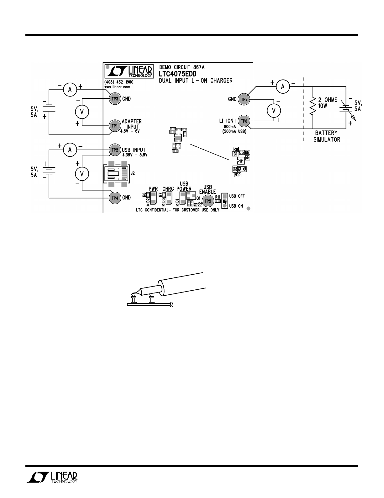
to Figure 1 for proper measurement equipment
setup and follow the procedure below:
The charger can be evaluated using an actual
Lithium Ion battery or a battery simulator. The battery simulator is faster because all battery state-ofcharge conditions can be quickly simulated.
A battery simulator consists of an adjustable
power supply with a load resistor across the power
supply output. The resistor value is selected that
will provide approximately 1A when the power
supply is set for 2.5V and power supply must provide at least 1.7A when adjusted for 4.2V. An example for battery simulator would be a 2 Ohm, 10
Watt power resistor connected to the output of a
5V, 5A bench supply.
1. With the input power supply and battery simu-
lator power supply adjusted to 0V, connect the
two power supply outputs to the
INPUT
GND
adapter charging mode. Make sure that
ENABLE
low for enabling AC adapter mode charging.
2. Increase the battery voltage to 3.6V. Observe
the 800mA battery charge current (measured
at input). Start to increase the adapter input
voltage. When the input supply voltage exceeds 4.2V, the charger should activate and
the PWR and CHRG LEDs will illuminate.
3. Increase the battery voltage to 4.2V and note
that the charge current falls to 0 and “CHRG”
LED will be turned off. This illustrates the con-
and
GND
terminals as shown in Figure 1 to test AC
terminal (turret) is floating or pulled
terminals; and
LI-ION+
ADAPTER
and
USB
stant voltage portion of the charging characteristic.
4. Set both power supply and battery simulator
back to 0V and connect the power supply (or
USB source) to
nals; and
shown in Figure 1 to test the USB charging
mode. Make sure that the
jumper is set to “
bling USB input charging mode.
5. Increase the battery voltage to 3.6V. Observe
the 476mA battery charge current (measured
at input). Start to increase the USB input voltage. When the input supply voltage exceeds
4V the charger should activate and the CHRG
LED will illuminate.
6. Test the USB shutdown mode by placing the
USB ENABLE
Note that the input current (or USB current)
falls to under 30uA to comply with the USB
shutdown mode.
7. Place jumper back to “
enabling USB charging. Increase the battery
voltage to 4.2V and note that the charge current falls to 0 and “CHRG” LED will be turned
off. This illustrates the constant voltage portion
of the charging characteristic. Note that the
input current (or USB current) decrease down
to 50uA, which is the typical USB current under standby mode (when the charging is terminated).
USB INPUT
LI-ION+
USB ON”
jumper to “
and
USB ON”
and
GND
GND
terminals as
USB ENABLE
position for ena-
USB OFF”
position.
position for
termi-
2
Page 3
QUICK START GUIDE FOR DEMONSTRATION CIRCUIT DC867
VIN
GND
DUAL INPUT USB / AC ADAPTER STANDALONE LI-ION CHARGER
Figure 1. Proper Measurement Equipment Setup
Figure 2. Measuring Input or Output Ripple
3
Page 4

QUICK START GUIDE FOR DEMONSTRATION CIRCUIT DC867
DUAL INPUT USB / AC ADAPTER STANDALONE LI-ION CHARGER
4
Page 5

Mouser Electronics
Authorized Distributor
Click to View Pricing, Inventory, Delivery & Lifecycle Information:
Analog Devices Inc.:
DC867A
 Loading...