

Page 1

QUICK START GUIDE FOR DEMONSTRATION CIRCUIT 1311
DESCRIPTION
TELECOM DC/DC CONVERTER
LTC3805/-5
Demonstration circuit 1311 is a Telecom isolated
DC/DC converter featuring the LTC3805/-5 constant
frequency current mode flyback controller. The
DC1311 converts 18V to 72V input voltage to an
isolated 3A of output current at 3.3V. The 300kHz
constant frequency operation is maintained down to
very light load to reduce low frequency noise
generated over a wide range of load current. The
converter provides high output voltage accuracy
(typically ±2%) over wide load range with no
minimum load requirement.
The DC1311 also provides non-isolated design by
removing opto coupler and LTC4430 circuit. The
demonstration circuit can be easily modified to
generate different output voltages up to 15V. As
QUICK START PROCEDURE
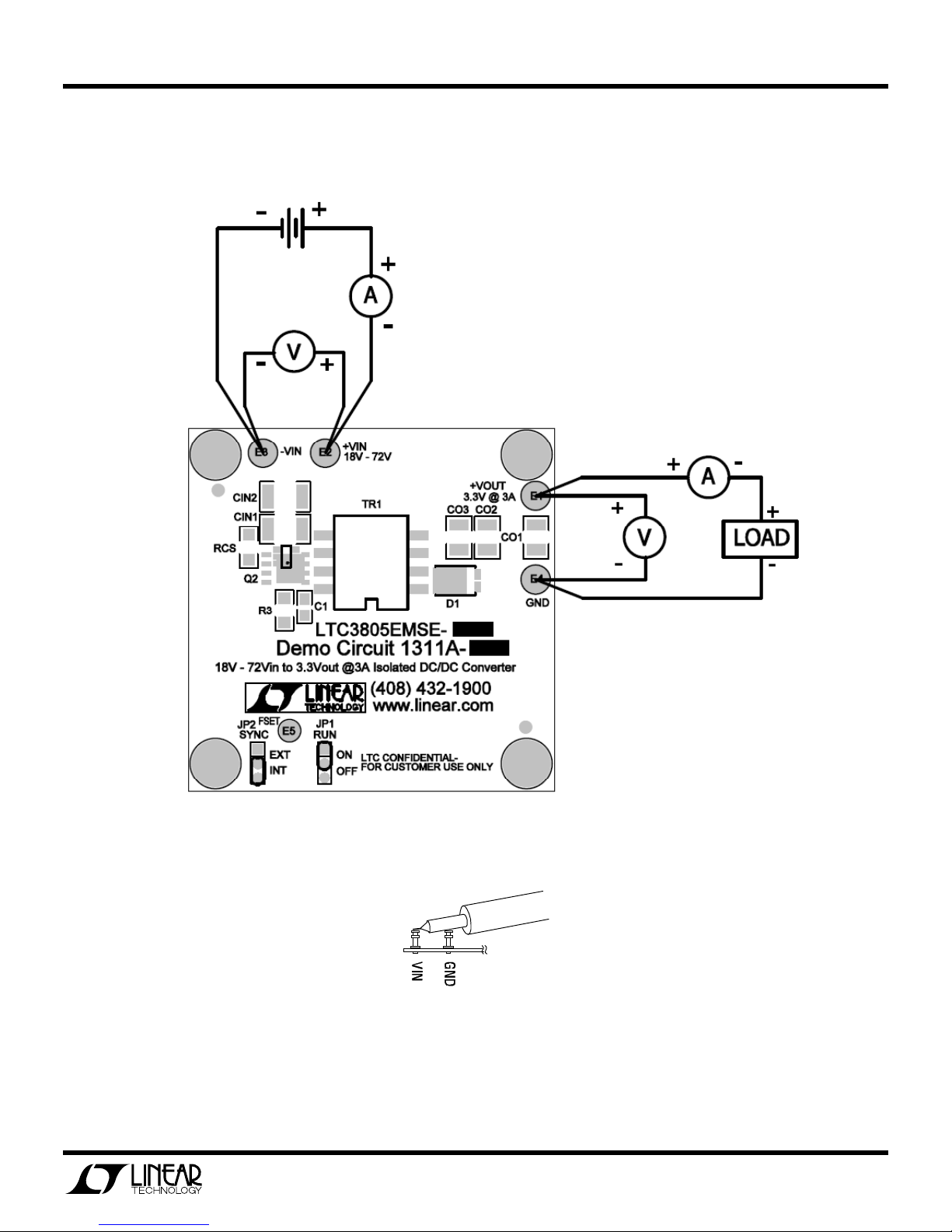
Demonstration circuit 1311 is easy to set up to
evaluate the performance of the LTC3805/-5. For
proper measurement equipment setup refer to
Figure 1 and follow the procedure below.
When measuring the input or output voltage ripple,
care must be taken to minimize the length of the
oscilloscope probe ground lead. Measure the input or
output voltage ripple by connecting the probe tip
directly across the VIN or V
see Figure 2.
1.
With power off, connect the input power supply to
+Vin and -Vin.
and GND terminals,
OUT
output voltage is increased, the maximum
output current must be reduced to limit the
output power to no more than 10W. Higher
output voltages and currents can be achieved by
changing the MOSFET, transformer and output
capacitors. Please consult LTC factory for details.
The DC1311 has a small circuit footprint. It is a high
performance and cost effective solution for Telecom,
Automotive and Power over Ethernet applications.
Design files for this circuit board are available. Call
the LTC factory.
LTC and LT are registered trademarks of Linear Technology Corporation.
power components with higher voltage ratings
should be used.
4.
Check for proper output voltage. Vout=3.3V.
If there is no output, temporarily disconnect the
load to make sure that the load is not set too high.
5.
To shut the converter down, move the RUN switch
into OFF position
6.
To synchronize converter to external clock, set
jumper JP2 (SYNC) to ‘EXT’ position, apply signal
to FSET pin. See LTC3805/-5 datasheet for
synchronization signal parameters.
2.
Move the J1 (RUN) switch to ON position.
3.
Turn the input power source on and slowly
increase the input voltage. Be careful not to exceed
72V. Make sure that the input voltage VIN does not
exceed 72V. If higher operating voltage is required,
7.
Once the proper output voltage is established,
adjust the load within 3.0A range and observe the
output voltage regulation, ripple voltage, efficiency
and other parameters.
1
Page 2
QUICK START GUIDE FOR DEMONSTRATION CIRCUIT 1311
TELECOM DC/DC CONVERTER
Figure 1. Proper Measurement Equipment Setup
Figure 2. Measuring Input or Output Ripple
2
Page 3
QUICK START GUIDE FOR DEMONSTRATION CIRCUIT 1311
TELECOM DC/DC CONVERTER
3
 Loading...