

Page 1
QUICK START GUIDE FOR DEMONSTRATION CIRCUIT 1031A-C
DESCRIPTION
36V-72VIN, SYNCHRONOUS FORWARD CONVERTER
LTC3725 / LTC3726
Demonstration circuit 1031A-C is a 36V-72Vin, synchronous forward converter featuring the
LTC3725/LTC3726. This circuit was designed specifically to attain a high current, low ripple, synchronously rectified forward to efficiently power 5.0V
loads at up to 20A from a typical telecom input volt-
trol of the supply eliminating the need for an optocoupler, self-starting architecture, input undervoltage
lockout, and output overvoltage protection.
Design files for this circuit board are available.
Call the LTC factory.
, LTC and LT are registered trademarks of Linear Technology Corporation.
age range. This circuit features secondary-side con-
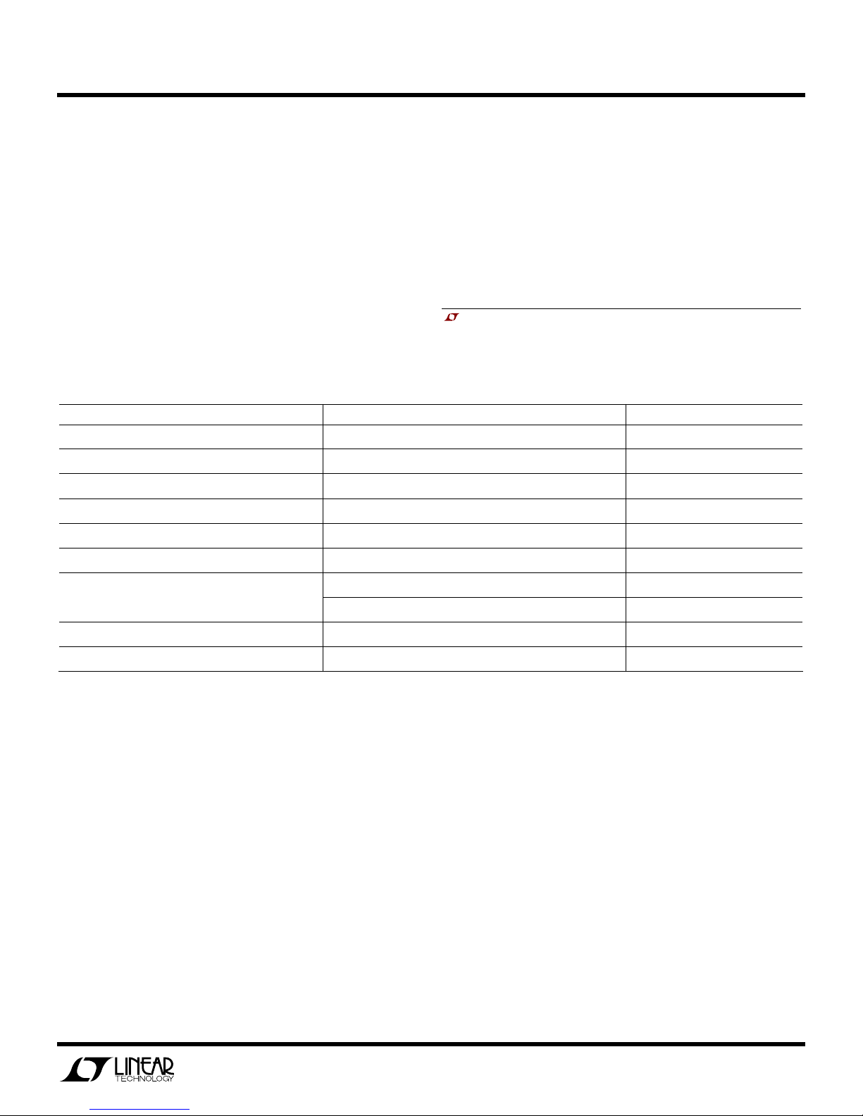
Table 1. Performance Summary (TA = 25°C)
PARAMETER CONDITION VALUE
Minimum Input Voltage 36V
Maximum Input Voltage 72V
Output Voltage V
Maximum Output Current 200LFM Airflow 20A
Typical Output Ripple V
Size Component Area x Top Component Height 2.3” x 0.9” x 0.394”
Load Transient Response
VIN = 36V to 72V, I
OUT
VIN = 72V, I
OUT
Peak Deviation with Load Step of 10A to 20A (10A/us) ±200mV
Settling Time 40us
= 0A to 20A 5.0V
OUT
= 20A 100mV
OUT
P–P
Nominal Switching Frequency 300kHz
Efficiency VIN = 48V, I
= 20A 91.5% Typical
OUT
OPERATING PRINCIPLES
The LTC3726 controller is used on the secondary and
the LTC3725 driver with self-starting capability is
used on the primary. When an input voltage is applied, the LTC3725 begins a controlled soft-start of
the output voltage. As this voltage begins to rise, the
LTC3726 secondary controller is quickly powered up
via T1, D1, and Q27. The LTC3726 then assumes
control of the output voltage by sending encoded
PWM gate pulses to the LTC3725 primary driver via
the small signal transformer, T2. The LTC3725 then
operates as a simple driver receiving both input signals and bias power through T2.
The transition from primary to secondary control occurs seamlessly at a fraction of the output voltage.
From that point on, operation and design simplifies to
that of a simple buck converter. Secondary sensing
eliminates delays, tames large-signal overshoot and
reduces output capacitance while utilizing off-theshelf magnetics and attaining high efficiency.
For large values of input inductance, a 100V, 47uF electrolytic capacitor can be added across the input terminals to damp the input filter and provide adequate stability. See Linear Technology Application Note AN19 for a
discussion on input filter stability analysis. A recommended part is the Sanyo 100MV39AX.
1
Page 2

QUICK START GUIDE FOR DEMONSTRATION CIRCUIT 1031A-C
36V-72VIN, SYNCHRONOUS FORWARD CONVERTER
QUICK START PROCEDURE
Demonstration circuit 1031A-C is easy to set up to
evaluate the performance of the LTC3725/LTC3726.
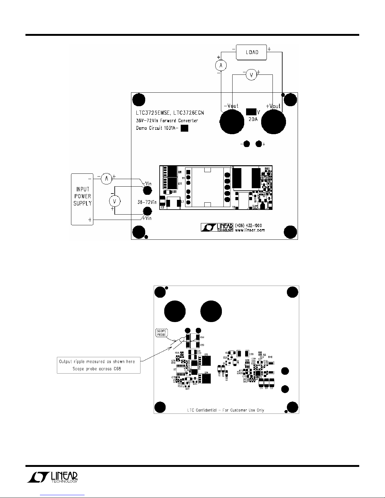
Refer to Figure 1 for proper measurement equipment
setup and follow the procedure below:
NOTE:
When measuring the input or output voltage
ripple, care must be taken to avoid a long ground lead
on the oscilloscope probe. Measure the output (or
input) voltage ripple by touching the probe tip and
probe ground directly across the input or output capacitor. See Figure 2 for proper scope probe technique.
1.
Set an input power supply that is capable of 36V to
72V at a current of at least 3.5A to a voltage of 36V.
Then, turn off the supply.
2.
With power off, connect the supply to the input
terminals +Vin and –Vin.
a.
Input voltages lower than 36V can keep the converter from turning on due to the undervoltage
lockout feature of the LTC3725/LTC3726.
3.
Turn on the power at the input.
NOTE:
Make sure that the input voltage never ex-
ceeds 72V.
4.
Check for the proper output voltage of 5.0V
5.
Turn off the power at the input.
6.
Once the proper output voltages are established,
connect a variable load capable of sinking 20A at
5.0V to the output terminals +Vout and –Vout. Set
the current for 0A.
a.
If efficiency measurements are desired, an ammeter or a resistor current shunt that is capable
of handling at least 20Adc can be put in series
with the output load in order to measure the
DC1031A-C’s output current.
b.
A voltmeter with a capability of measuring at
least 5.0V can be placed across the output terminals in order to get an accurate output voltage
measurement.
b.
If efficiency measurements are desired, an ammeter capable of measuring 3.5Adc can be put
in series with the input supply in order to measure the DC1031A-C’s input current.
c.
A voltmeter with a capability of measuring at
least 72V can be placed across the input terminals in order to get an accurate input voltage
measurement.
7.
Turn on the power at the input.
NOTE:
If there is no output, temporarily disconnect
the load to make sure that the load is not set too
high.
8.
Once the proper output voltage is established, adjust the load within the operating range and observe the output voltage regulation, ripple voltage,
efficiency and other desired parameters.
2
Page 3
QUICK START GUIDE FOR DEMONSTRATION CIRCUIT 1031A-C
36V-72VIN, SYNCHRONOUS FORWARD CONVERTER
Figure 1. Proper Measurement Equipment Setup
Figure 2. Measuring Input or Output Ripple
3
Page 4
QUICK START GUIDE FOR DEMONSTRATION CIRCUIT 1031A-C
86
88
90
92
94
6 8 10 12 14 16 18 20
LOAD CURRENT (A)
EFFICIENCY (%)
36V
48V
72V
36V-72VIN, SYNCHRONOUS FORWARD CONVERTER
MEASURED DATA
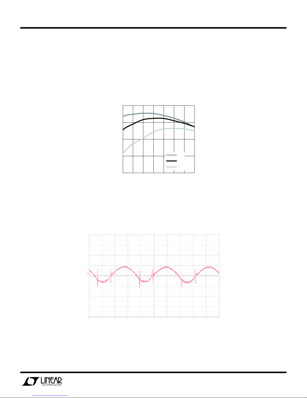
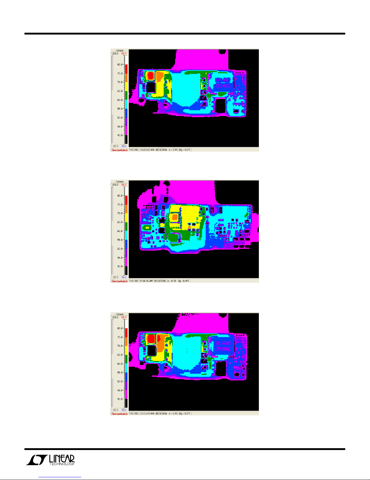
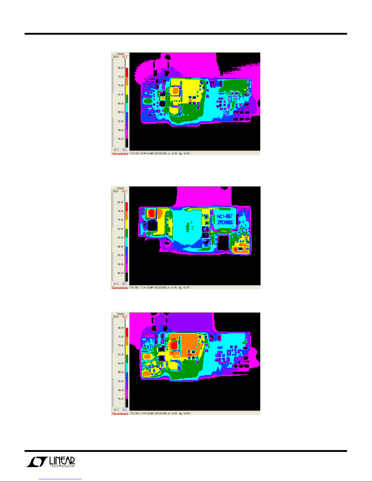
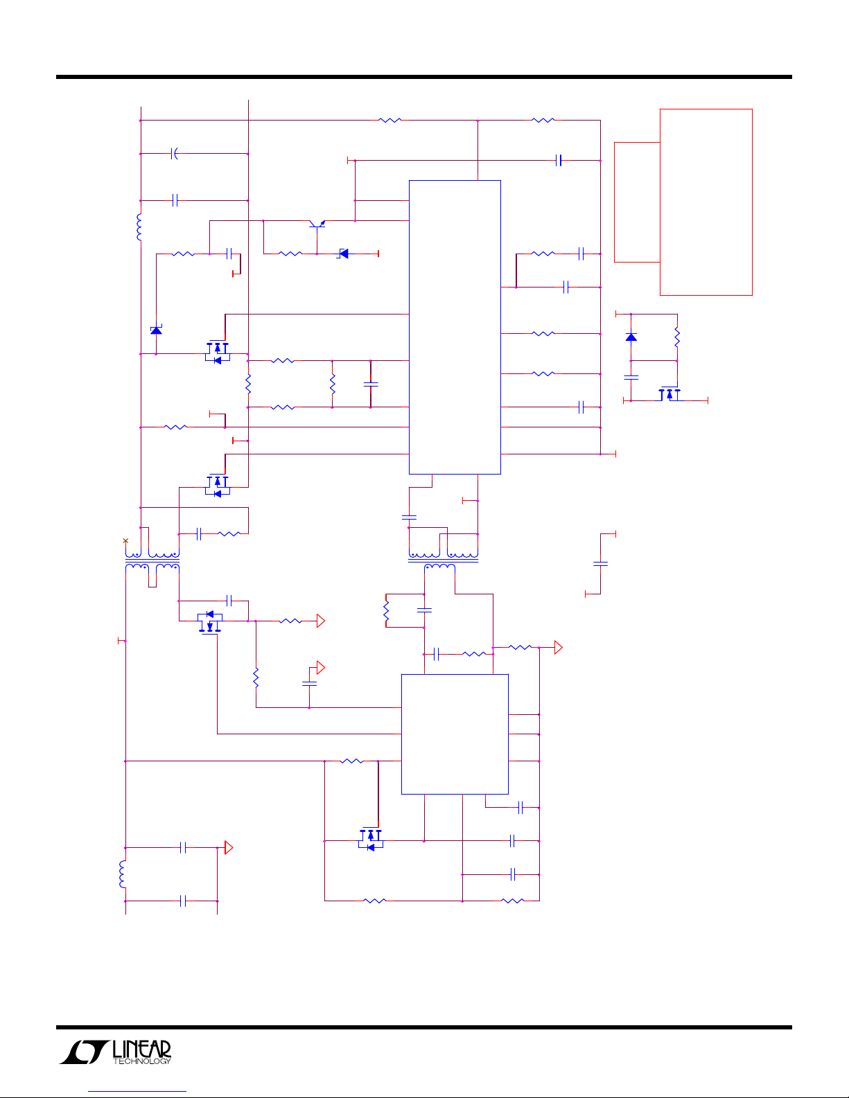
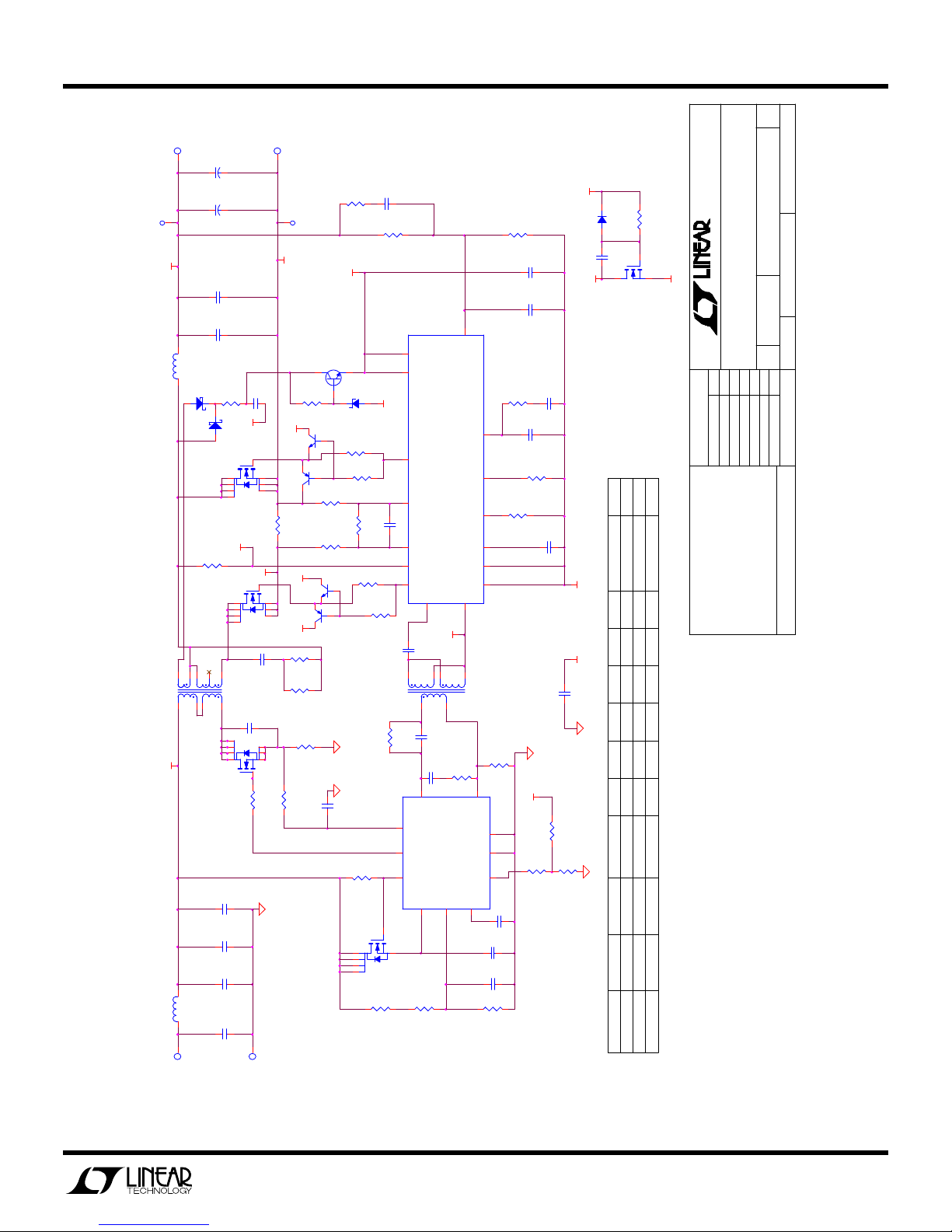
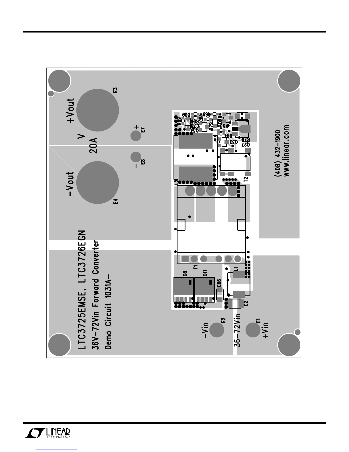
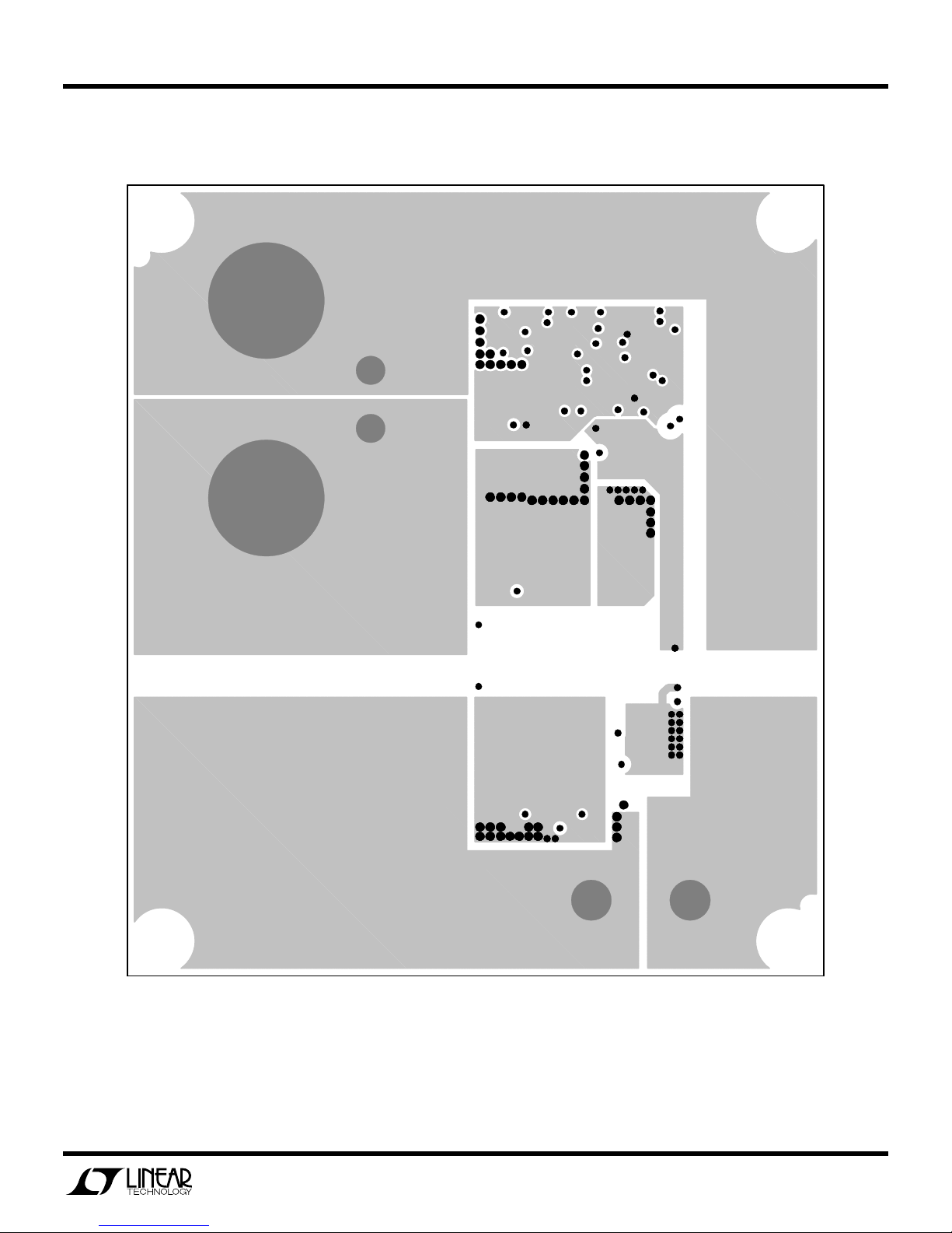
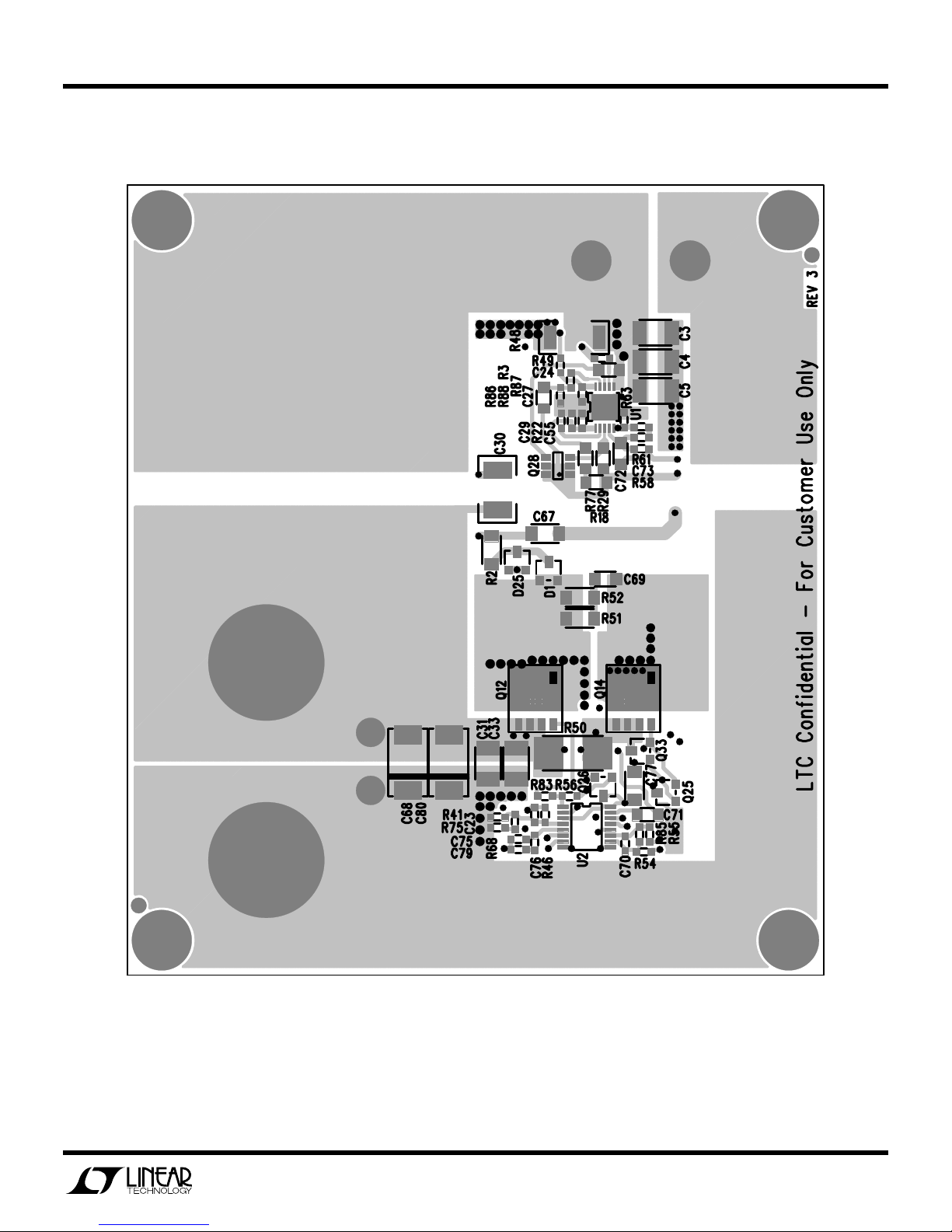
Figures 3 through 11 are measured data for a typical DC1031A-C. Figures 12 through 21 are schematics, bill of materials and layout.
Figure 3. Efficiency (200lfm airflow)
50mV/div
1us/div
Figure 4. Output Ripple Voltage (72Vin, 20Aout)
4
Page 5
QUICK START GUIDE FOR DEMONSTRATION CIRCUIT 1031A-C
36V-72VIN, SYNCHRONOUS FORWARD CONVERTER
Vout
200mV/DIV
Iout
10A/div
20us/DIV
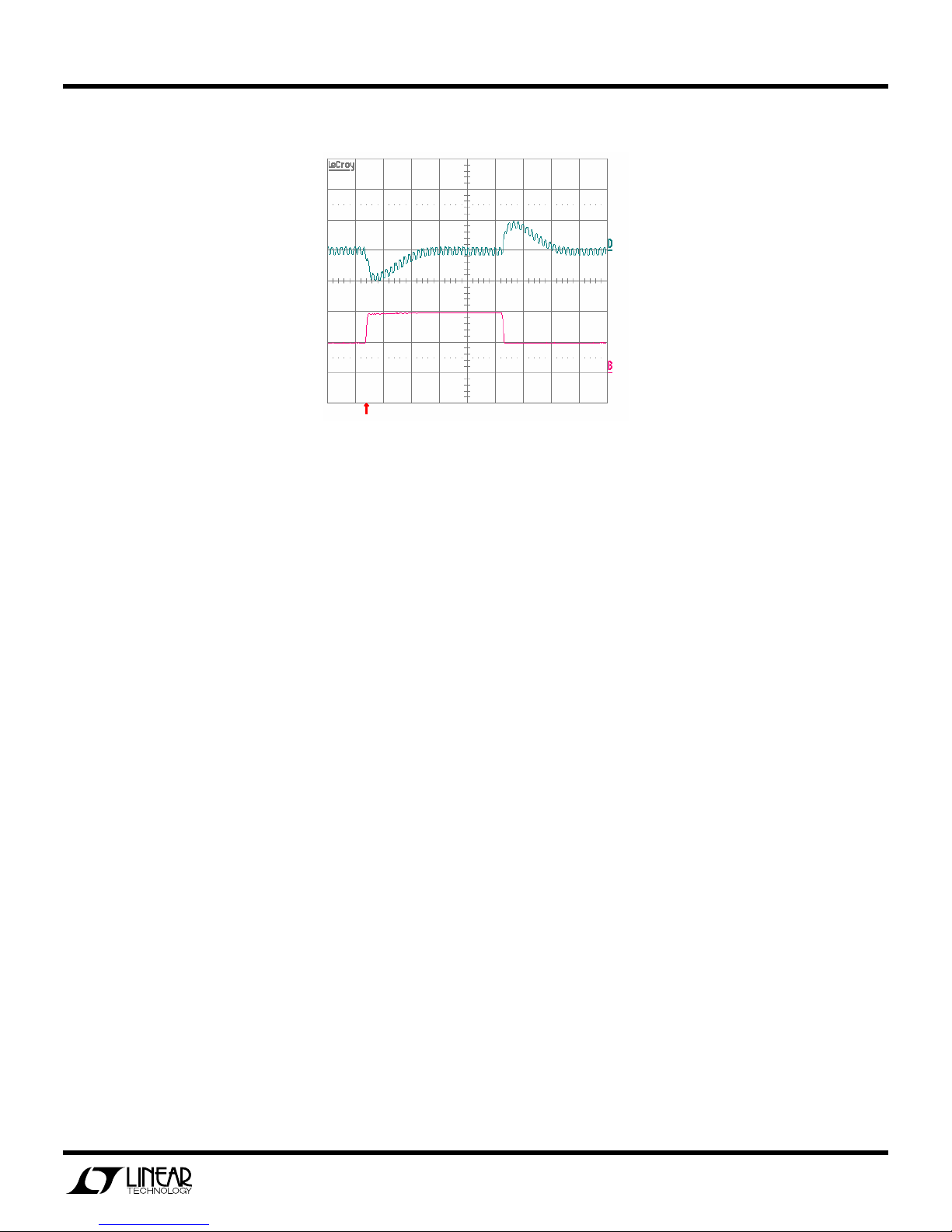
Figure 5. Output Voltage Transient Response (48Vin, 10A to 20A step)
5
Page 6
QUICK START GUIDE FOR DEMONSTRATION CIRCUIT 1031A-C
36V-72VIN, SYNCHRONOUS FORWARD CONVERTER
Figure 6. Temp Data (48Vin, 20A, 25C, 200LFM airflow – front)
Figure 7. Temp Data (48Vin, 20A, 25C, 200LFM airflow – back)
Figure 8. Temp Data (36Vin, 20A, 25C, 200LFM airflow – front)
6
Page 7
QUICK START GUIDE FOR DEMONSTRATION CIRCUIT 1031A-C
Figure 9. Temp Data (36Vin, 20A, 25C, 200LFM airflow – back
36V-72VIN, SYNCHRONOUS FORWARD CONVERTER
Figure 10. Temp Data (72Vin, 20A, 25C, 200LFM airflow – front)
Figure 11. Temp Data (72Vin, 20A, 25C, 200LFM airflow – back)
7
Page 8
QUICK START GUIDE FOR DEMONSTRATION CIRCUIT 1031A-C
36V-72VIN, SYNCHRONOUS FORWARD CONVERTER
604
4.42K
+Vout
C68
6.3V
220uF
+
6.3V
2x100uF
L2
C31,C33
0.87uH
1/4W
R2
C67
1.2
-Vout
5.0V/20A
25V
4.7uF
VCC
Q27
FCX491
(SOT89)
1K
R76
D1
CMPSH1-4
Q12
VA
Si7336ADP
1/4W
D28
R85
3.01K
R55
100
R50
1W
R79
510
VSW
Si7336ADP
Q14
0.002
R54
100
VA
2.4
R51
115
T1
23.4 x 20.1 x 9.4mm PLANAR
VIN
72
10
C69
4
3 9
Si7450DP
Q8
1/4W
50V
1.5nF
1nF
C66
200V
0.022
R48
1W
R3
100
330pF
C27
R29
3x1.0uF
C3,C4,C5
100V
Q28
R41
4
MO DE
3
V CC
16
-VOUT
MMBZ5236B
7.5V
C70
R58
100K
S G
1
IS +
11
U2
330pF
IS -
10
S W
12
FG
2
PT+
15
C71
634
T2
1
C72
5.1K
C73
4
FB/IN+
IS
10
G AT E
7
ND RV
3
FB/PH
IT H
FS/S YNC
LT C372 6EGN
1uF
8
0.1uF
470pF
S LP
RU N/S S
P GND
G ND
PT-
14
PT-
5
100
R61
5
FS/IN-
U1
LT C372 5EM SE
UL VO
VCC
(SOT6)
FDC2512
8
SSFLT
2
1
R46
C77
2.2uF
C79
2.2nF
6.2K
R68
C75
5
9
7
6
13
8
R63
100K
G ND
11
P GND
6
V SLMT
9
C29
C24
1uF
47pF
124K
R69
100K
R66
C78
VIN
33nF
CONFI DENTIAL
LINEAR TECH NOLOGY CO RPORATION
PT-
D29
C81
33nF
VSW
-VOUT
-VOUT
C30
2.2nF
250V
CUSTOMER NOTICE
WI TH LTC PARTS.
THIS C IRCUI T IS DISTRIBUTED
TO C USTOMERS ON LY FOR USE
LINEA R TEC HNOLOG Y HA S MADE A BES T EF FO RT T O DES IGN A C IRCUIT
THA T ME ETS CUSTO MER-SUP PLIED S PECIF ICAT IONS; HO WEV ER, IT
536
R89
1N4148W
10pF
Q34
2N7002
TE CHNOLO GY A PPLICAT ION S ENGI NEERING FO R ASSIS TANCE .
AF FECT CIRCUIT PERF ORMA NCE OR RE LIABI LITY. CONTA CT LINE AR
SUB STIT UTIO N AND PRIN TED CIR UIT BO ARD LA YOUT MAY S IGNIF ICANT LY
RELIA BLE O PERAT ION IN THE A CTUAL APPLI CATIO N. COM PONEN T
REMA INS T HE CUST OME R'S RESPO NSIBIL ITY T O V ERIFY PROP ER AND
-VOUT
L1
1uH
C2
1.0uF
100V
+Vin
36-72Vin
-Vin
R18
365K
Figure 12. Simplified Schematic
C55
470pF
100uF, 6.3V CER TDK C3225X5R0J107M (1210)
1uF,100V TDK C3225X7R2A105M (1210)
C68 Sanyo 6TPE220MI
C30 Murata GA343QR7GD222KW01L (1812)
L1 Vishay IHLP-2525CZER1R0M-01
T2 Pulse PA0297 2(1.4mH):1:1
L2 Cooper HC1-R87
T1 PA0811 (4:4:2:1)
R22
15.0K
8
Page 9
QUICK START GUIDE FOR DEMONSTRATION CIRCUIT 1031A-C
36V-72VIN, SYNCHRONOUS FORWARD CONVERTER
A
1
REV
+Vout
E3
C80
6.3V
220uF
+
C68
6.3V
220uF
+
+
E7
+VOUT
C31
100uF
C33
100uF
L2
0.87uH
D25
*
R2
5
Q12
678
Si7336ADP
R79
510
Q14
Si7336ADP
T1
*
11531098
72
4
6 7 8
6 7 8
opt.
Q11
5
VIN
5
Q8
Si7450DP
C5
1.0uF
C4
1.0uF
C3
1.0uF
-Vout
E4
opt.
opt.
C23
R75
opt.
-
E8
6.3V
6.3V
1.2
D1
*
VSW
5
678
100V
100V
100V
-VOUT
C67
4.7uF
25V
1/4W
VA
VCC
Q26
4
1
opt.
23
Q32
R50
1W
0.002
VA
VCC
4
1
23
VA
R52
*
50V
C69
R51
200V
C66
1nF
2 3
2 3
1
1
4
4
0
R3
R49
100
23
R76
1K
1206
opt.
opt.
1/4W
2.4
1/4W
1W
R48
*
C27
VCC
Q27
FCX491
1
R83
R55
100
1%
R54
100
1%
opt.
Q25
opt.
Q33
330pF
R41
*
4
MODE
3
16
-VOUT
D28
7.5V
0
MMBZ5236B
1
opt.
R56
11
*
R85
C70
330pF
10
12
2
0
R84
opt.
R53
T2
1
C72
5.1K
R58
4
IS
10
7
R29
100K
3
8
3
Q28
FDC2512
2
5
6
4 1
FB/PH
VCC
SG
IS+
IS-
SW
FG
PT+
PT-
15
14
PT-
1uF
C71
634
5
8
0.1uF
470pF
C73
R61
FB/IN+
GATE
U1
NDRV
LTC3725EMSE
UL VO
VCC
1
R46
604
C77
2.2uF
C76
opt.
R68
6.2K
ITH
5
R69
FS/SYNC
SLP
RUN/SS
PGND
GND
100
5
FS/IN-
GND
PGND
VSLMT
SSFL T
2
C24
C55
*
9
R66
100K
7
6
13
8
U2
LTC3726EGN
R63
*
VIN
11
6
R87
9
C29
33nF
1uF
470pF
PT-
Phone: (408)432-1900
Fax: (408)434-0507
Milpitas, CA 95035
D29
C81
VSW
C79
2.2nF
47pF
C75
C78
33nF
-VOUT
-VOUT
C30
2.2nF
250V
opt.
R86
0
0
R88
*
R89
1N4148W
1
10pF
Q34
2N7002
C69
2.2nF
PA0865(4:4:1:1)
PA0815(6:6:2:1)
910
opt
opt
R85
0
0
R69
R63
160K
160K
R48 T1
0.039
0.039 2.2nF
R41 R89
2.74K
1.91K 910
D25
CMPSH1-4
CMPSH1-4
D1
opt.
opt.
Vout/Iout
3.3V/20A
2.5V/20A
1630 McCarthy Blvd.
2 3
1.5nF
TECHNOLOGY
-VOUT
TITLE
DATE
J. W U 12/5/05
APPROVALS
CONTRACT NO.
CHECKED
DRAWN
CUSTOMER NOTICE
536
3.01K
124K
100K5.0V/20A
0.022
4.42K PA0811(4:4:2:1)
opt.
CMPSH1-4
LINEAR TECHNOLOGY HAS MADE A BEST EFFORT TO DESIGN A
CIRCUIT THAT MEETS CUSTOMER-SUPPLIED SPECIFICATIONS;
HOWEVER, IT REMAINS THE CUSTOMER'S RESPONSIBILITY TO
VERIFY PROPER AND RELIABLE OPERATION IN THE ACTUAL
OF
1
SHEET
DC1031 A
DWG NO
FILENAME:
CAGE CODE
LTC3725EMSE, LTC3726EGN, 36V - 72Vin Forward Converter
SIZE
SCALE:
K. Mathews 12/5 /05
Wednesday , August 23, 2006
ENGINEER
DESIGNER
APPROVED
THIS CIRCUIT IS PROPRIETARY TO LINEAR TECHNOLOGY AND
SUPPLIED FOR USE WITH LINEAR TECHNOLOGY PARTS.
CIRUIT BOARD LAYOUT MAY SIGNIFICANTLY AFFECT CIRCUIT
TECHNOLOGY APPLICATIONS ENGINEERING FOR ASSISTANCE.
PERFORMANCE OR RELIABILITY. CONTACT LINEAR
APPLICATION. COMPONENT SUBSTITUTION AND PRINTED
L1
1.0uH
C2
1.0uF
100V
E1
+Vin
36-72Vin
E2
-Vin
R18
0
R77
365K
R22
15.0K
Figure 13. Full Board Schematic
VERSION TAB LE
*
VERSION
DC1031A-A
DC1031A-B
DC1031A-C
T2 Pulse PA0297 2(1.4mH):1:1
L2 Coil Tronics HC1-R87
L1 Vishay IHLP-2525CZER1R0M-01 or
C68 Sanyo 6TPE220MI
C2-C5 1uF,100V TDK C3225X7R2A105M (1210)
For All The Versions
COOPER HCP0703-1R0-R
C31,C33 100uF, 6.3V CER TDK C3225X5R0J107M (1210)
9
Page 10
QUICK START GUIDE FOR DEMONSTRATION CIRCUIT 1031A-C
36V-72VIN, SYNCHRONOUS FORWARD CONVERTER
Item Qty Reference Part Description Manufacture / Part #
REQUIRED CIRCUIT COMPONENTS1
1 4 C2,C3,C4,C5 CAP., X7R, 1.0uF, 100V, 20%, 1210 TDK, C3225X7R2A105M
2 2 C71,C24 CAP., X7R, 1uF, 16V 10%, 0805 TAIYO YUDEN, EMK212BJ105KG
3 2 C27,C70 CAP., X7R, 330pF, 25V, 10%, 0603 AVX, 06033C331KAT2A
4 2 C29,C78 CAP., X7R, 33nF, 25V, 10%, 0603 AVX, 06033C333KAT2A
5 1 C30 CAP., X7R, 2.2nF, 250V, 10%, 1812 MURATA, GA343QR7GD222KW01L
6 2 C31,C33 CAP., X5R, 100uF, 6.3V, 20%, 1210 TDK, C3225X5R0J107M
7 2 C73,C55 CAP., C0G, 470pF, 25V, 10%, 0603 AVX, 06033A471KAT2A
8 1 C66 CAP., C0G, 1nF, 200V, 10%, 1206 AVX, 12062A102KAT2A
9 1 C67 CAP., X7R, 4.7uF, 25V, 20%, 1206 TDK, C3216X7R1E475M
10 1 C68 CAP., POSCAP, 220uF, 6.3V, 20% 7343 SANYO, 6TPE220MI
11 1 C69 CAP., NPO, 1.5nF, 50V, 10%, 0805 AVX, 08055A152KAT2A
12 1 C72 CAP., X7R, 0.1uF, 25V, 10%, 0805 AVX, 08053C104KAT2A
13 1 C75 CAP., NPO, 47pF, 25V, 10%, 0603 AVX, 06033A470KAT2A
14 1 C77 CAP., X7R, 2.2uF, 16V, 20%, 1206 TDK, C3216X7R1C225M
15 1 C79 CAP., X7R, 2.2nF, 25V, 10%, 0603 AVX, 06033C222KAT2A
16 1 C81 CAP., C0G, 10pF, 50V, 5%, 0603 AVX, 06035A100JAT2A
17 1 D1 DIODE, Schottky, CMPSH1-4, 40V, SOT23 CENTRAL SEMI., CMPSH1-4-LTC
18 1 D28 Diode, MMBZ5236B, SOT23 DIODES INC., MMBZ5236B-7
19 1 D29 Diode, 1N4148W SOD-123 DIODES INC., 1N4148W-7-F
20 1 L1 INDUCTOR, 1.0uH VISHAY DALE, IHLP2525CZER1R0M01
0 L1 (second source) INDUCTOR, 1.0uH COOPER, HCP0703-1R0-R
21 1 L2 INDUCTOR, 0.87uH COOPER, HC1-R87
22 1 Q8 FET, N-CH,. Si7450DP, POWERPAK SO-8 VISHAY, Si7450DP
23 2 Q12,Q14 FET, N-CH,. Si7336ADP, POWERPAK SO-8 VISHAY, Si7336ADP
24 1 Q34 N-CH., Transistor. 2N7002 SOT23 DIODES INC., 2N7002-7-F
25 1 Q27 NPN TRANSISTOR, FCX491 ZETEX, FCX491
26 1 Q28 N-CH FET, 150V, FDC2512, Super SOT-6 FAIRCHILD, FDC2512
27 1 R2 RES., CHIP, 1.2, 1/4W, 5%, 1206 AAC, CR18-1R2JM
28 2 R54,R55 RES., CHIP, 100, 1/16W, 1%, 0603 VISHAY, CRCW06031000FRT6
29 1 R18 RES., CHIP, 365K, 1/8W, 1%, 0805 VISHAY, CRCW0805365KFKEB
30 1 R22 RES., CHIP, 15.0K, 1/16W, 1%, 0603 AAC, CR16-1502FM
31 1 R29 RES., CHIP, 100K, 1/8W, 5%, 0805 AAC, CR10-104JM
32 1 R41 RES., CHIP, 4.42K, 1/16W,1%, 0603 AAC, CR16-4421FM
33 1 R46 RES., CHIP, 604, 1/16W, 1%, 0603 AAC, CR16-6040FM
34 1 R48 RES., CHIP, 0.022, 1W, 2%, 2010 IRC, LRC-LRF2010-01-R022-G
35 1 R50 RES., CHIP, 0.002, 1W, 1%, 2512 PANASONIC, ERJM1WTF2M0U
36 1 R51 RES., CHIP, 2.4, 1/4W, 5%, 1206 AAC, CR18-2R4JM
37 1 R58 RES., CHIP, 5.1K, 1/16W, 5%, 0603 AAC, CR16-512JM
38 2 R3,R61 RES., CHIP, 100, 1/16W, 5%, 0603 AAC, CR16-101JM
39 2 R63,R66 RES., CHIP, 100K, 1/16W, 5%, 0603 AAC, CR16-104JM
40 1 R68 RES., CHIP, 6.2K, 1/16W, 5%, 0603 AAC, CR16-622JM
41 1 R69 RES., CHIP, 124K, 1/16W, 1%, 0603 AAC, CR16-1243FM
42 1 R76 RES., CHIP, 1K, 1/4W, 5%, 1206 AAC, CR18-102JM
43 1 R79 RES., CHIP, 510, 1/8W, 5%, 0805 e3 AAC, CR10-511JM
44 1 R85 RES., CHIP, 3.01K, 1/16W, 1%, 0603 AAC, CR16-3011FM
10
Page 11
QUICK START GUIDE FOR DEMONSTRATION CIRCUIT 1031A-C
36V-72VIN, SYNCHRONOUS FORWARD CONVERTER
45 1 R89 RES., CHIP, 536, 1/16W, 5%, 0603 AAC, CR16-5360FM
46 1 T1 TRANSFORMER, 1750VDC BASIC, PA0811 PULSE, PA0811
47 1 T2 TRANSFORMER, 1500VRMS BASIC, PA0297 PULSE, PA0297
48 1 U1 I.C., LTC3725EMSE, MS10E LINEAR TECH., LTC3725EMSE
49 1 U2 I.C., LTC3726EGN, SSOP16GN LINEAR TECH., LTC3726EGN
ADDITIONAL DEMO BOARD CIRCUIT COMPONENTS2
1 0 C23,C76 (opt.) CAP., 0603
2 0 C80 (opt.) CAP., POSCAP, 220uF, 6.3V, 20% 7343
3 0 D25 (opt.) DIODE, Schottky, CMPSH1-4, 40V, SOT23
4 0 Q11 (opt.) FET, N-CH, POWERPAK SO-8
5 0 Q25,Q26 (opt.) NPN Transistor, FMMT619, SOT23
6 0 Q32,Q33 (opt.) PNP Transistor, FMMT718, SOT23
7 5 R49,R83,R84,R87,R88 RES., CHIP, 0, 1/16W, 0603 Panasonic, ERJ3GEY0R00V
8 0 R52 (opt.) RES., CHIP, 1206
9 0 R53,R56,R75 (opt.) RES., CHIP, 0603
11 1 R77 RES., CHIP, 0, 1/8W, 0805 AAC, CJ10-000M
12 0 R86 (opt.) RES., CHIP, 0805
HARDWARE-FOR DEMO BOARD ONLY:
1 2 E1,E2 TESTPOINT, TURRET, .094" MILL-MAX, 2501-2
2 2 E3,E4 STUD PEM, KFH-032-10
3 4 E3,E4
4 2 E3,E4 Ring, Lug Ring # 10 KEYSTONE 8205
5 2 E3,E4 WASHER, STAR #10 BRASS NICHEL ANY
6 2 E8,E7 TURRET, MILL-MAX2308-2-00-44
7 4 (STAND-OFF) STAND-OFF, NYLON 0.50" KEYSTONE 8833 (SNAP ON)
Notes:
1. Required Circuit Components are those parts that are required to implement the circuit function
2. Additional Demo Board Circuit Components are those parts that provide added functionality for the demo board but
are not required in the actual circuit.
(2 EACH)
NUT, BRASS, #10-32 ANY
Figure 14. Bill of Materials
11
Page 12
QUICK START GUIDE FOR DEMONSTRATION CIRCUIT 1031A-C
36V-72VIN, SYNCHRONOUS FORWARD CONVERTER
Figure 15. Top
12
Page 13
QUICK START GUIDE FOR DEMONSTRATION CIRCUIT 1031A-C
36V-72VIN, SYNCHRONOUS FORWARD CONVERTER
Figure 16. Layer 2
13
Page 14
QUICK START GUIDE FOR DEMONSTRATION CIRCUIT 1031A-C
36V-72VIN, SYNCHRONOUS FORWARD CONVERTER
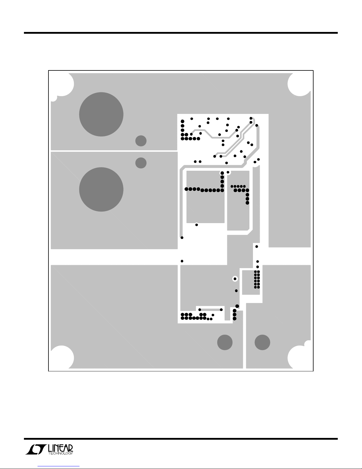
Figure 17. Layer 3
14
Page 15
QUICK START GUIDE FOR DEMONSTRATION CIRCUIT 1031A-C
36V-72VIN, SYNCHRONOUS FORWARD CONVERTER
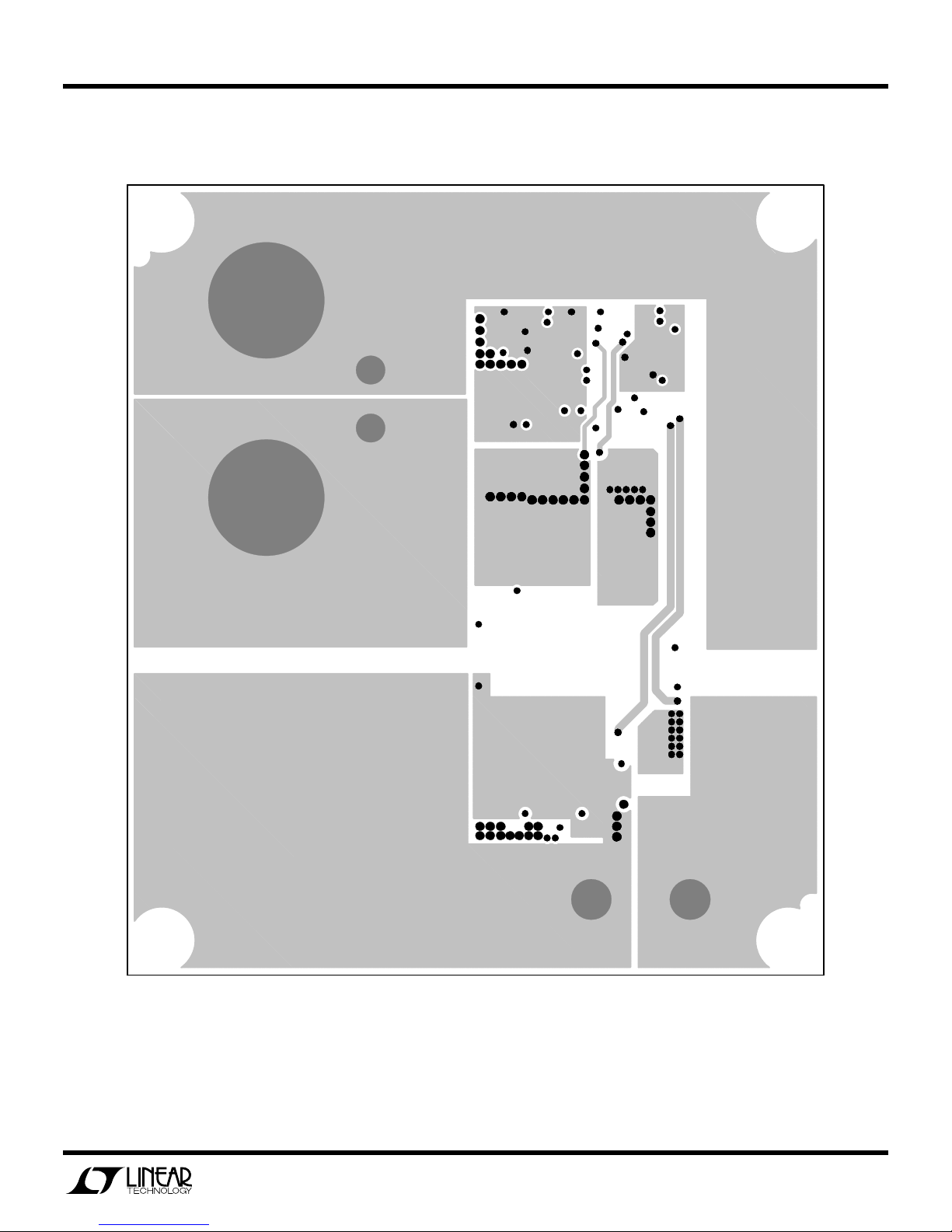
Figure 18. Layer 4
15
Page 16
QUICK START GUIDE FOR DEMONSTRATION CIRCUIT 1031A-C
36V-72VIN, SYNCHRONOUS FORWARD CONVERTER
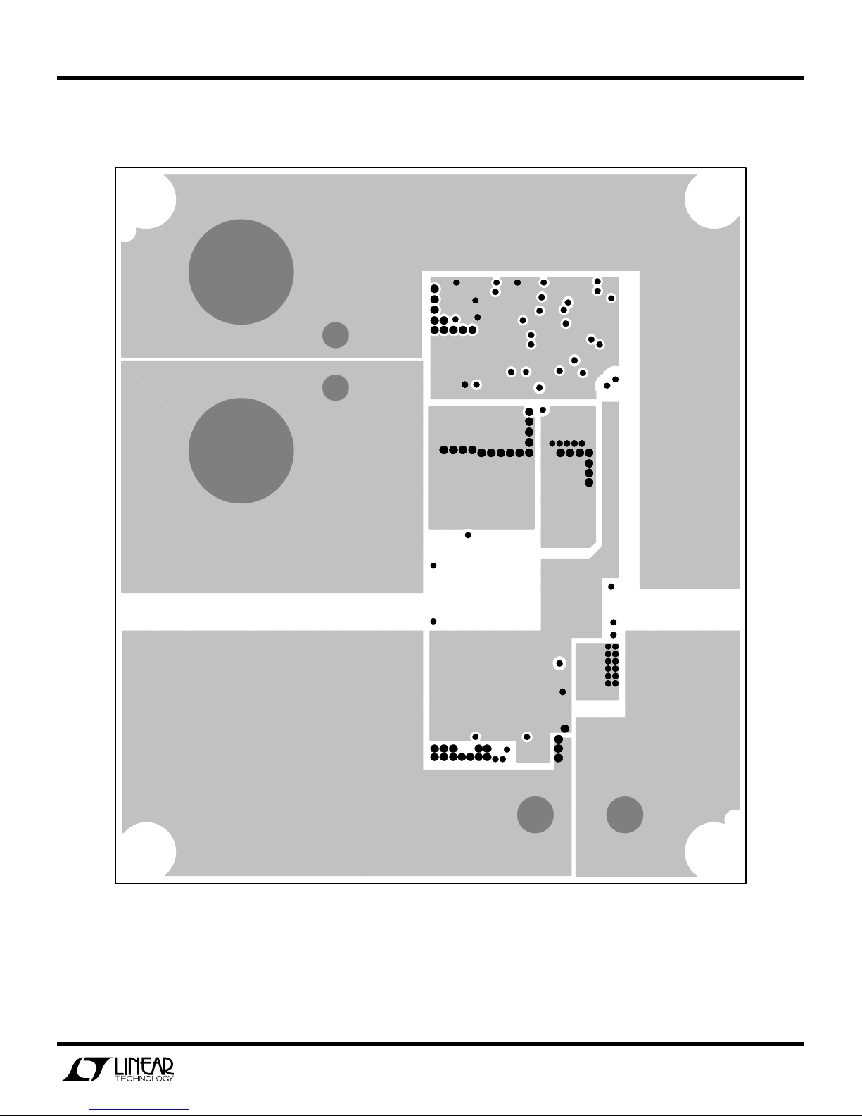
Figure 19. Layer 5
16
Page 17
QUICK START GUIDE FOR DEMONSTRATION CIRCUIT 1031A-C
36V-72VIN, SYNCHRONOUS FORWARD CONVERTER
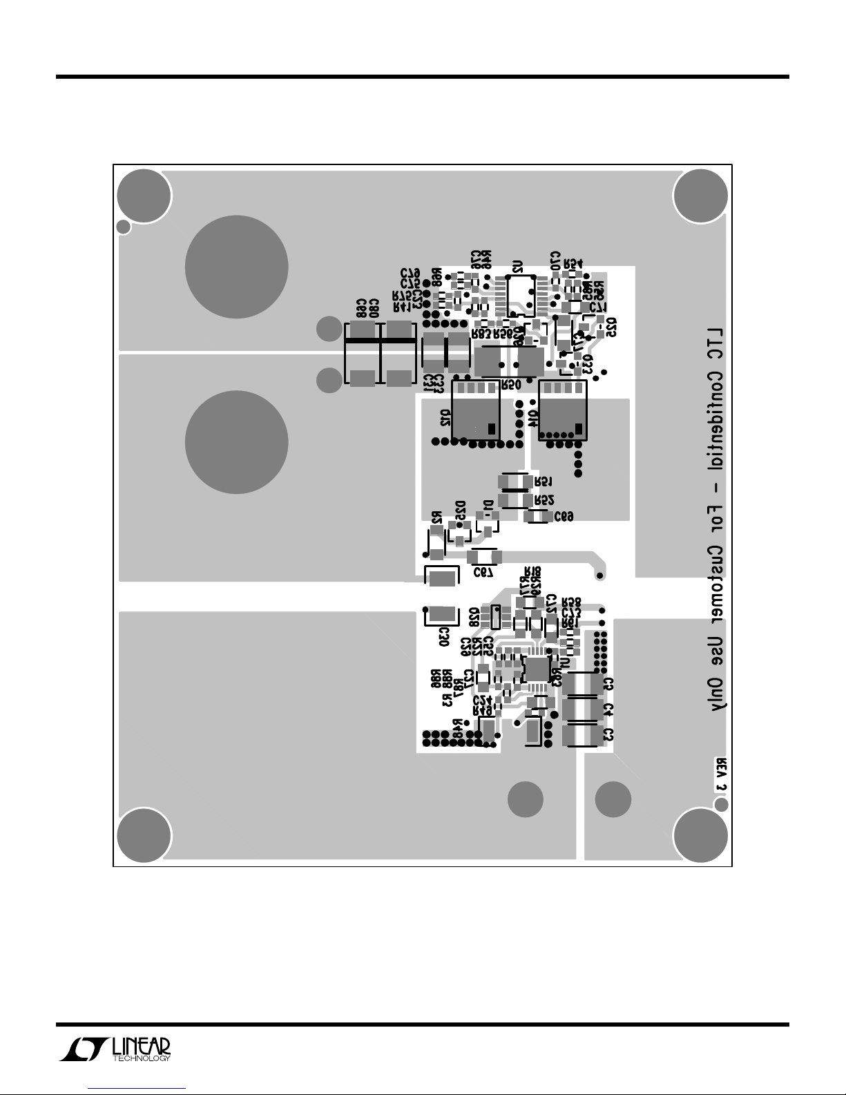
Figure 20. Bottom
17
Page 18
QUICK START GUIDE FOR DEMONSTRATION CIRCUIT 1031A-C
36V-72VIN, SYNCHRONOUS FORWARD CONVERTER
Figure 21. Bottom Mirrored
18
Page 19

Mouser Electronics
Authorized Distributor
Click to View Pricing, Inventory, Delivery & Lifecycle Information:
Analog Devices Inc.:
DC1031A-C
 Loading...