

Page 1
LTC3212
1
V
mV
V
1187
QUICK START GUIDE
LTC3212
RGB LED Driver and
Charge Pump
DESCRIPTION
DEMO CIRCUIT
WARNING!
Do not look directly at operating LED.
This circuit produces light that can damage eyes.
Demonstration circuit 1187 is an RGB LED Driver
and Charge Pump featuring the LTC3212.
The LTC3212 is a low noise charge pump capable
of driving three LEDs up to 25mA each. This device requires only one flying capacitor, two by-pass
capacitors, and one to three programming resistors. Each LED may be turned on individually, in
ing a single wire interface. White mode optimizes
the red, green, and blue current settings to provide
the best white color.
LED currents are regulated using internal low
dropout current sources. Automatic mode switching optimizes efficiency by switching modes only
when a dropout is detected. Refer to the LTC3212
datasheet for more information on this device.
Design files for this circuit board are available.
Call the LTC factory.
L
, LTC, LTM, and LT are registered trademarks of Linear Technology Corporation.
Other product names may be trademarks of the companies that manufacture the
products.
combination with each other, or in white mode us-
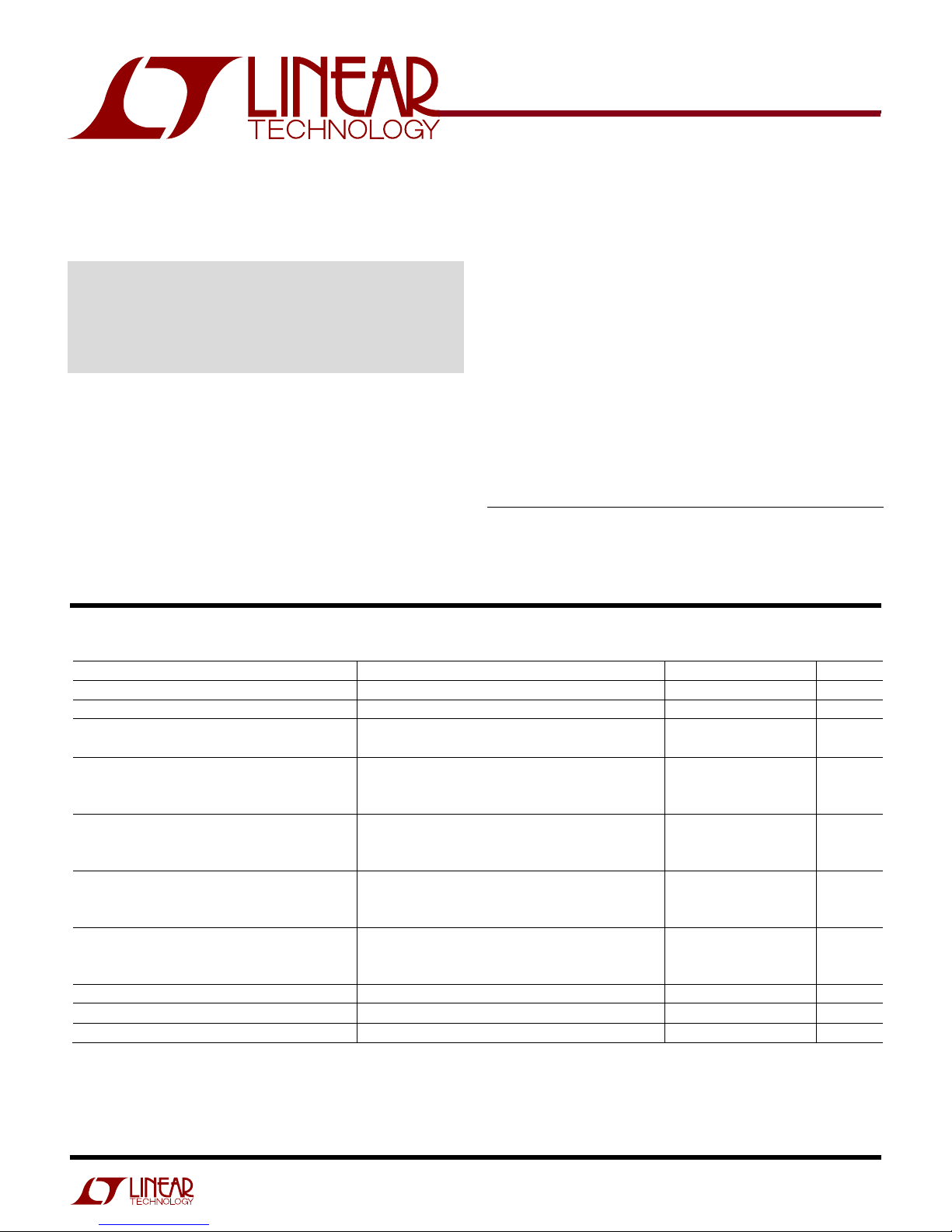
PERFORMANCE SUMMARY
PARAMETER CONDITIONS MIN TYP MAX UNITS
Input Supply Range
I
Shutdown Current LEDEN = LOW 3 8 µA
VIN
I
Operating Current
VIN
I
R
LED
I
(WHITE MODE)
LEDG
I
(WHITE MODE)
LEDB
I
(WHITE MODE) R
LEDR
I
Dropout Voltage (V
LED
Charge Pump Output Clamp Voltage
I
CPO
) Mode Switching Threshold, I
ILED
Specifications are at TA = 25°C
I
= 0mA, 1X Mode
CPO
I
= 0mA, 2X Mode
CPO
= 33.87KΩ (Not in White Mode)
ISET
R
= 58.87KΩ (Not in White Mode)
ISET
R
= 8.87KΩ (Not in White Mode)
ISET
R
= 33.87K
ISETG
R
= 58.87K
ISETG
R
= 8.87KΩ
ISETG
R
= 33.87K
ISETG
R
= 58.87K
ISETG
R
= 8.87KΩ
ISETG
= 33.87K
ISETG
R
= 58.87K
ISETG
R
= 8.87KΩ
ISETG
Ω
Ω
Ω
Ω
Ω
Ω
2.7 5.5
0.4
2.0
5.24
3.0
20.0
5.24
3.0
20.0
3.93
2.62
15.0
4.72
2.71
18.0
= 15mA 150
LED
5.1
0 75 mA
mA
mA
mA
mA
mA
mA
mA
mA
mA
mA
mA
mA
mA
mA
Page 2

LTC3212
2
OPERATING PRINCIPLES
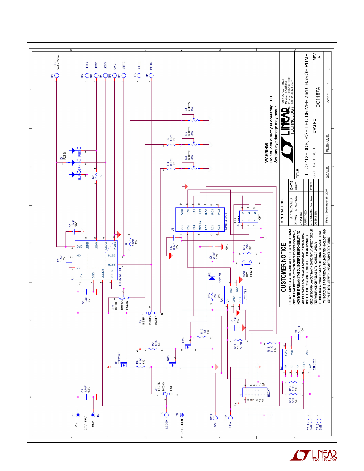
The DC1187 has a programmable IC on board that
communicates to the DC590 USB to I2C board
and drives the LTC3212 via a single wire interface.
The current in each LED output is set by adjusting
the resistance at the associated ISET pin. Each
ISET pin is connected to an 8.87KΩ resistor in series with a 50KΩ potentiometer. This allows the
user to adjust each ISET resistance between
8.87KΩ and 58.87KΩ to experiment with different
QUICK START PROCEDURE
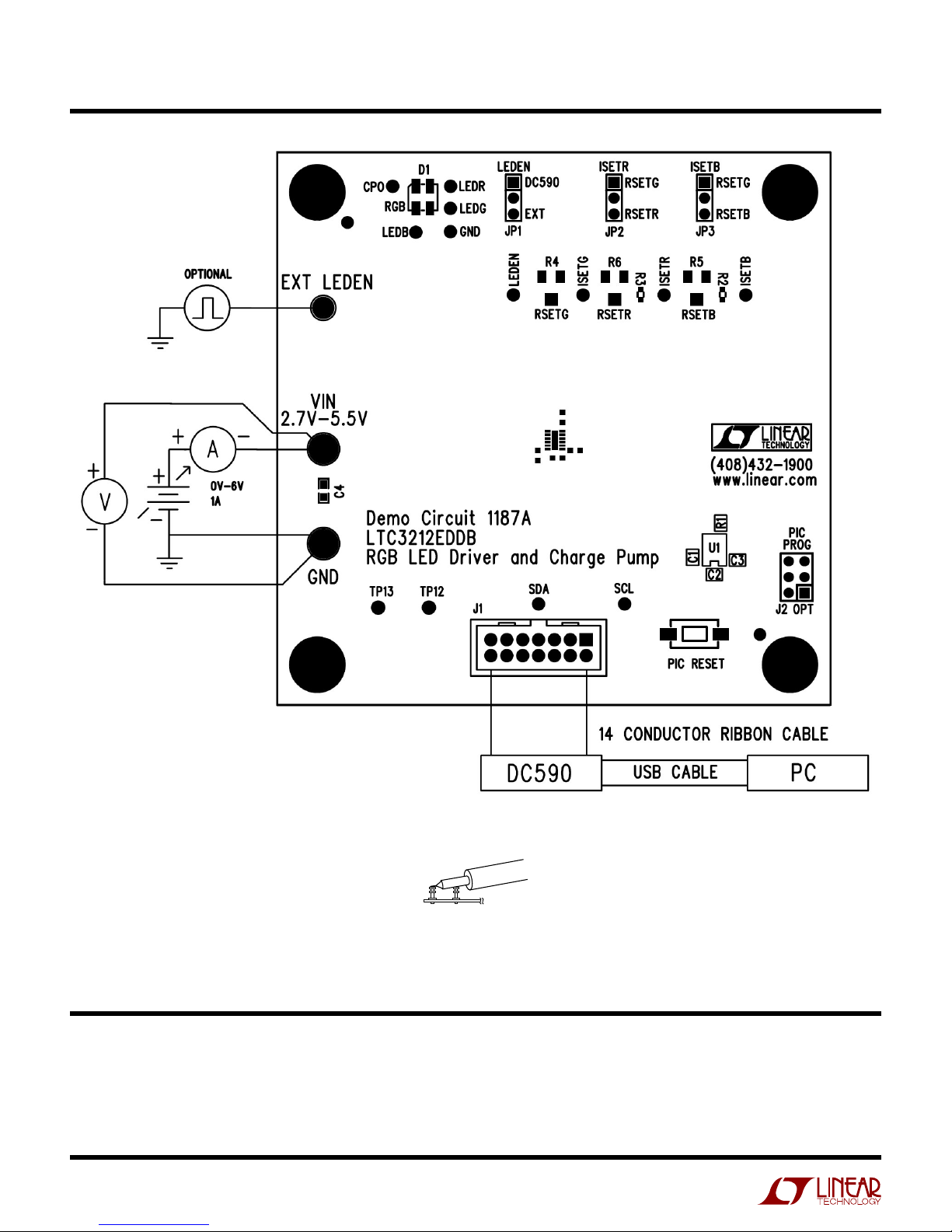
Demonstration circuit 1187 is easy to set up to
evaluate the performance of the LTC3212. Refer to
Figure 1 for proper measurement equipment setup
and follow the procedure below:
NOTE.
When measuring the input or output voltage ripple, care
must be taken to avoid a long ground lead on the oscilloscope
probe. Measure the input or output voltage ripple by touching the
probe tip directly across the VIN or CPO and GND terminals. See
Figure 2 for proper scope probe technique.
1.
Place jumpers in the following positions:
JP1 LEDEN:
JP2 ISETR:
JP3 ISETB:
2.
Make sure that the RSETG, RSETR, and
RSETB potentiometers are set approximately to
the center position (adjustment slot is
perpendicular to top of board).
3.
Refer to the DC590 Quick Start Guide for
QuikEvalTM setup and software installation
details.
4.
If using the DC590B board, make sure the
VCCIO jumper, JP6, on the DC590B board is
set to the 5V position. The microcontroller on
the DC1187 board needs 5V to operate
properly.
5.
Make sure the USB cable is connected between
the computer and the DC590 controller board.
Up, DC590 position.
Down, RSETR position.
Down, RSETB position.
color variations and intensities. The current for
LEDG is set by the RSETG potentiometer, R4. The
currents for LEDR and/or LEDB are also set by the
RSETG potentiometer when in white mode and
when ISETR and/or ISETB are tied to VIN via JP2
and JP3 respectively. Otherwise, the LEDR and
LEDB output currents are set by the RSETR potentiometer, R6, and RSETB potentiometer, R5,
respectively.
6.
Connect DC1187 to the DC590 USB Serial Controller using the supplied 14-conductor ribbon
cable as shown in Figure 1.
7.
With power off, connect the input power supply
to VIN and GND with a series ammeter and a
voltmeter as shown in Figure 1.
8.
Turn on the input power supply and set the VIN
voltage to 3.6V.
NOTE.
Make sure that the input voltage does not exceed 6V.
9.
Run the QuikEval program. The program detects the DC1187 and displays the LTC3212
control window (shown in Figure 3).
10.
Select the Green/Red option button on the
LTC3212 control window and observe that the
RGB LED illuminates light greenish.
11.
Adjust RSETG fully counterclockwise and observe that the RGB LED changes to a yellowish
green color.
12.
Adjust RSETR fully clockwise and observe that
the RGB LED color changes to light orange.
13.
Move the ISETR jumper from the RSETR position to the RSETG position and observe that the
RGB LED color changes to light green.
14.
Select the Blue/Green option button on the
LTC3212 control window and observe that the
RGB LED illuminates light blue.
Page 3

LTC3212
3
15.
Slowly adjust RSETB fully counterclockwise
then adjust RSETG fully clockwise. Observe
that the RGB LED changes from light blue to
greenish blue.
16.
Move the ISETB jumper from RSETB to
RSETG and observe the RGB LED color
change.
17.
Select the Blue/Red option button on the
LTC3212 control window and observe that the
RGB LED illuminates bluish red.
18.
Move the ISETR jumper to the RSETR position
and the ISETB jumper to the RSETB position.
Observe that the LED illuminates pink.
19.
Select the White Mode option button on the
LTC3212 control window. Observe that the RGB
illuminates a whitish color.
20.
Slowly adjust the RSETG potentiometer fully
counter-clockwise and observe that the LED
changes intensity but not color.
21.
Select the LEDs OFF option button and turn off
power when done.
Page 4
LTC3212
4
VIN
GND
Figure 1. Proper Measurement Equipment Setup
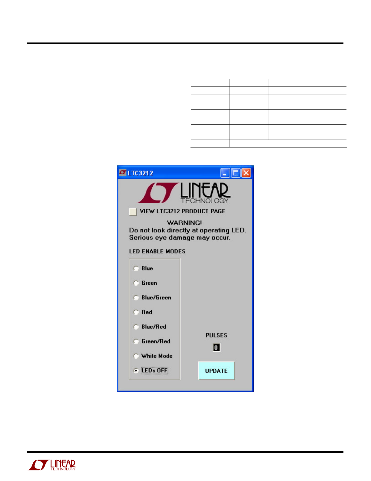
LTC3212 SOFTWARE CONTROL WINDOW
The LTC3212 software control window consists of
7 LED Enable Mode option buttons, which allow
the user to select which LEDs to turn on or off, or
Figure 2. Measuring Input or Output Ripple
select white mode. White mode turns on the three
LEDs at an optimal intensity to display white light.
A Pulse text box displays how many pulses were
Page 5
LTC3212
5
sent to the LTC3212. The Update button updates
the microcontroller with the proper timing information and updates the LTC3212 to match the selected LED Enable mode option button. The Update button will need to be selected if whenever
VIN applied, the 14 conductor ribbon cable is connected, if the DC590 board is connected, or if the
PIC RESET button on the DC1187 board was depressed. The PIC RESET button resets the PIC
microcontroller on the demo board. The “View
LTC3212 Product Page” button searches the LTC
web site for the LTC3212, providing an internet
connection is available.
LED ENABLE SETTINGS
PULSES R G B
0 0 0 0
1 0 0 1
2 0 1 0
3 0 1 1
4 1 1 0
5 1 0 1
6 1 0 0
7+ WHITE MODE
Figure 3. LTC3212 Control Window
Page 6
LTC3212
6
Page 7
LTC3212
7
Page 8

Mouser Electronics
Authorized Distributor
Click to View Pricing, Inventory, Delivery & Lifecycle Information:
Analog Devices Inc.:
DC1187A
 Loading...