

Page 1
DEMO MANUAL DC2025A
GROUND
MEASURE REF VOLTAGE,
GROUND
OUTPUTS
OUTPUT
PULLED TO OVP W/5kΩ
SOFTSPAN RANGES)
16-Channel 16-Bit/12-Bit
±10V V
DESCRIPTION
Demonstration circuit 2025A features the LT C®2668,
16-channel 16-Bit/12-Bit ±10V V
10ppm/°C max reference in a 6mm × 6mm QFN package.
This device features per-channel SoftSpan configuration
with five output ranges: 0V to 5V, 0V to 10V, ±2.5V, ±5V,
and ±10V. A toggle feature allows any or all DACs to switch
between two programmed codes via a single SPI command
or by the TGP input pin. The versatile SPI interface can
operate on any logic level between 1.71V and 5.5V, for
easy interface to lower voltage microcontrollers or FPGAs.
ANALOG SUPPLIES
(±15V ALLOWS ALL
SoftSpan™ DACs with
OUT
OUT
SoftSpan DACs with
10ppm/°C Max Reference
DC2025A-A is populated with the 16-bit version of the
LTC2668. DC2025A-B is populated with the 12-bit version
for lower resolution applications.
Design files for this circuit board are available at
http://www.linear.com/demo/DC2025A
L, LT, LTC, LTM, Linear Technology and the Linear logo are registered trademarks and
SoftSpan and QuikEval are trademarks of Analog Devices, Inc. All other trademarks are the
property of their respective owners.
MUX OUTPUT
DAC
OUTPUTS
SIGNAL
+
–
+
–
DAC
OUTPUTS
SIGNAL
OVERTEMPERATURE
SEE TEXT. LDAC, TGP, CLR
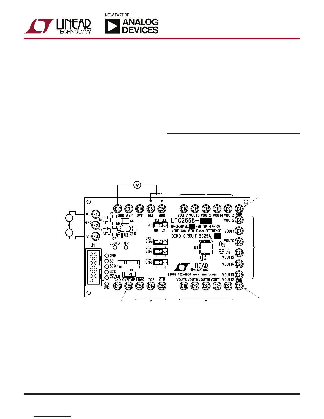
Figure 1. Connection Diagram
DAC
dc2025afa
1
Page 2
DEMO MANUAL DC2025A
QUICK START PROCEDURE
Download and install QuikEval™ from:
http://www.linear.com/designtools/software/#Data
Connect a DC590 controller or DC2026 Linduino with
DC590 emulator firmware to the DC2025A with the supplied
ribbon cable. Connect low-noise analog power supplies
as shown in Figure 1. A ±15V supply will allow all of the
SoftSpan ranges to be used, refer to the LTC2668 data
sheet for other supply options if not all SoftSpan ranges
are used.
Connect the controller to the host PC’s USB port and run
QuikEval. The DC2025A software will be downloaded and
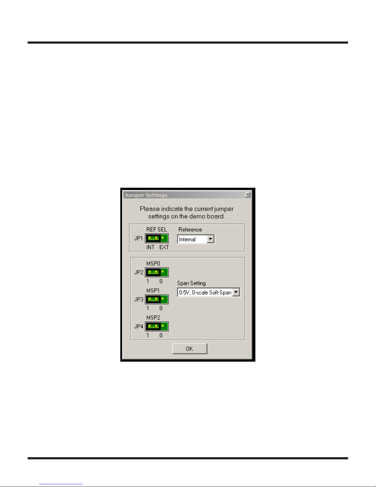
installed, after which a jumper setting window will appear
as shown in Figure 2. The default settings are internal
reference, SoftSpan operation with 0V to 5V range, 0V
output on power-up. If the jumpers on the board have been
changed to a different configuration, select the appropri
ate options in the pull-down menus to match the board.
Click OK and the main dialog will appear. The control panel
gives access to all of the LTC2668’s functionality includ
ing per-channel SoftSpan ranges, toggling, Power-Down,
etc. Detailed instructions are provided in the Help menu.
-
-
2
Figure 2. Jumper Settings Dialog
dc2025afa
Page 3

QUICK START PROCEDURE
DEMO MANUAL DC2025A
Figure 3. Main Control Panel
dc2025afa
3
Page 4

DEMO MANUAL DC2025A
QUICK START PROCEDURE
External Connections
J1: Interface connector to DC590 controller or Linduino.
Provides OVP power, SPI interface, and board identifica
tion.
–
, GND, V+: Analog supplies, connected to the LTC2668
V
+
and V– pins. Nominally ±15V for operation in all Soft-
V
Span ranges. Refer to the data sheet for other supply
configurations.
GND: Four additional ground posts and exposed ground
plane around board edge allow solid connection to pro
totype circuitry and measurement equipment.
AVP: Analog supply voltage. Normally supplied by an on
board LT1761-5 fixed 5V regulator that is powered from
+
supply. For single 5V supply applications, AVP
the V
may be tied directly to V
OVP: Digital interface power. No connection to this pin is
required when used with a DC590 or Linduino controller.
If another controller is used, connect to digital supply that
powers the SPI bus controller (1.71 to 5.5V).
REF: Connection to the REF pin. In internal reference
mode, the reference voltage may be monitored at this
point. Placing REF_SEL jumper in the EXT position allows
an external reference to be connected to this point.
+
and supplied with 4.5V to 5.5V.
MUX: Monitor Mux output. Allows surveying
outputs under software control. Must be measured with
a high impedance meter (output impedance is nominally
-
2.1kΩ).
VOUT0 to VOUT15: DAC outputs.
CLR: Asynchronous clear input (pulled high to OVP with
a 4.99k resistor). Pull to ground to reset the DAC to the
power-on reset value (determined by MSPx pins.)
TGP: Toggle input (pulled high to OVP with a 4.99k resis
-
tor). A high level on this pin enables software toggling. See
data sheet for a complete description of toggle operation.
-
LDAC: Asynchronous DAC update. If CS/LD is high at the
falling edge of LDAC, DAC outputs will be updated with
the contents of the input registers. If CS/LD is low when
LDAC goes low, the DAC registers are updated after CS/
LD returns high.
OVRTMP: Overtemperature pin (pulled high to OVP with a
4.99k resistor). The LTC2668 pulls this pin low if the die
temperature exceeds approximately 160°C. It is released
on the next rising edge of CS/LD.
the DAC
-
4
dc2025afa
Page 5

QUICK START PROCEDURE
DEMO MANUAL DC2025A
Jumpers
REF_SEL (JP1): Selects internal or external reference
mode. (See data sheet description of REFCOMP pin.)
MSP0, MSP1, MSP2 (JP2, JP3, JP4): Manual Span
control. Setting all jumpers to the 1 position (Default)
selects SoftSpan operation, with a power-up default span
of 0V to 5V, and reset to Zero-Scale. Other options are
listed in Table 1.
LEDs
OVRTMP: Lights when OVRTMP pin asserts, indicating an
overtemperature state. (Note that LED will light if positive
analog supply is present and OVP is not. OVP is normally
supplied by the controller.)
Test Points
The SPI bus is available on a row of through-hole test
points next to J1 that may be used to monitor the bus or
to drive the bus with an external controller.
EEGND, WP: For factory use only.
Table 1
MSP2 MSP1 MSP0 OUTPUT RANGE RESET CODE MANUAL SPAN SoftSpan
0 0 0 ±10V Mid-Scale X
0 0 1 ±5V Mid-Scale X
0 1 0 ±2.5V Mid-Scale X
0 1 1 0V to 10V Zero-Scale X
1 0 0 0V to 10V Mid-Scale X
1 0 1 0V to 5V Zero-Scale X
1 1 0 0V to 5V Mid-Scale X
1 1 1 0V to 5V Zero-Scale X
Information furnished by Linear Technology Corporation is believed to be accurate and reliable.
However, no responsibility is assumed for its use. Linear Technology Corporation makes no representation that the interconnection of its circuits as described herein will not infringe on existing patent rights.
dc2025afa
5
Page 6

DEMO MANUAL DC2025A
DEMONSTRATION BOARD IMPORTANT NOTICE
Linear Technology Corporation (LT C ) provides the enclosed product(s) under the following AS IS conditions:
This demonstration board (DEMO BOARD) kit being sold or provided by Linear Technology is intended for use for ENGINEERING DEVELOPMENT
OR EVALUATION PURPOSES ONLY and is not provided by LT C for commercial use. As such, the DEMO BOARD herein may not be complete
in terms of required design-, marketing-, and/or manufacturing-related protective considerations, including but not limited to product safety
measures typically found in finished commercial goods. As a prototype, this product does not fall within the scope of the European Union
directive on electromagnetic compatibility and therefore may or may not meet the technical requirements of the directive, or other regulations.
If this evaluation kit does not meet the specifications recited in the DEMO BOARD manual the kit may be returned within 30 days from the date
of delivery for a full refund. THE FOREGOING WARRANTY IS THE EXCLUSIVE WARRANTY MADE BY THE SELLER TO BUYER AND IS IN LIEU
OF ALL OTHER WARRANTIES, EXPRESSED, IMPLIED, OR STATUTORY, INCLUDING ANY WARRANTY OF MERCHANTABILITY OR FITNESS
FOR ANY PARTICULAR PURPOSE. EXCEPT TO THE EXTENT OF THIS INDEMNITY, NEITHER PARTY SHALL BE LIABLE TO THE OTHER FOR
ANY INDIRECT, SPECIAL, INCIDENTAL, OR CONSEQUENTIAL DAMAGES.
The user assumes all responsibility and liability for proper and safe handling of the goods. Further, the user releases LT C from all claims
arising from the handling or use of the goods. Due to the open construction of the product, it is the user’s responsibility to take any and all
appropriate precautions with regard to electrostatic discharge. Also be aware that the products herein may not be regulatory compliant or
agency certified (FCC, UL, CE, etc.).
No License is granted under any patent right or other intellectual property whatsoever. LTC assumes no liability for applications assistance,
customer product design, software performance, or infringement of patents or any other intellectual property rights of any kind.
LT C currently services a variety of customers for products around the world, and therefore this transaction is not exclusive.
Please read the DEMO BOARD manual prior to handling the product. Persons handling this product must have electronics training and
observe good laboratory practice standards. Common sense is encouraged.
This notice contains important safety information about temperatures and voltages. For further safety concerns, please contact a LTC application engineer.
Mailing Address:
Linear Technology
1630 McCarthy Blvd.
Milpitas, CA 95035
Copyright © 2004, Linear Technology Corporation
6
dc2025afa
LT 0617 REV A • PRINTED IN USA
LINEAR TECHNOLOGY CORPORATION 2014
 Loading...