

Page 1
SOT-23 Comparator and Voltage
Reference for Battery Monitoring
FEATURES
■
High Accuracy Trip Voltage: 1% Max Error Using
External 1% Resistors
■
Adjustable Threshold Voltage and Hysteresis
■
Quiescent Current: 2.5µA Typ
■
Output Swings Rail-to-Rail
■
Thresholds Programmable from 2.5V to 3.25V
■
Output State Guaranteed for V
■
Low Profile (1mm) ThinSOT
BATT
TM
Package
≥ 1.5V
LTC1998
2.5µA, 1% Accurate
U
DESCRIPTIO
The LTC®1998 is a micropower comparator and a precision adjustable reference in a 6-pin SOT-23 package that
is optimized for lithium-ion low battery detection circuits.
The LTC1998 features a voltage detection circuit with an
adjustable threshold voltage and hysteresis. The threshold voltage can be programmed from 2.5V to 3.25V with
two external resistors. A 10mV to 750mV hysteresis can
be added with a third external resistor.
U
APPLICATIO S
■
Lithium-Ion Battery-Powered Equipment
PDAs
Cell Phones
Handheld Instruments
Battery Packs
Pagers
Palm Top Computers
POS Terminals
, LTC and LT are registered trademarks of Linear Technology Corporation.
ThinSOT is a trademark of Linear Technology Corporation.
W
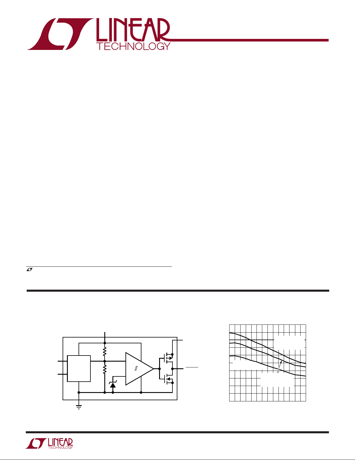
BLOCK DIAGRA
BATT
1.1R
V
HYST.A
V
TH.A
THRESHOLD
ADJUST
R
1.2V
A proprietary internal architecture maintains 1% threshold voltage accuracy over temperature with low cost 1%
external resistors.
A separate power supply pin, V
, allows the battery-
LOGIC
low logic output to operate below the battery voltage,
allowing compatibility with low voltage microprocessors
without a pull-up resistor. Power supply glitches are
eliminated by preventing the cross-conducting current
which occurs when the output changes state.
The LTC1998 operates with battery or supply voltages up
to 5.5V and its battery-low output is valid for battery
voltages above 1.5V.
Threshold Voltage Error vs Temperature
1.0
0.9
V
SET BY 1%
V
LOGIC
BATTLO
1998 BD
0.8
0.7
0.6
V
0.5
% ERROR
0.4
0.3
0.2
0.1
0
–45 15 55
1V
TH.A =
THRESHOLD = 3V
–25 –5
TEMPERATURE (°C)
TH.A
EXTERNAL R,
THRESHOLD = 3V
V
SHORTED
TH.A
TO GROUND,
THRESHOLD = 2.5V
35 75 95
1998 G05
1998f
1
Page 2
LTC1998
WW
W
ABSOLUTE AXI U RATI GS
U
UUW
PACKAGE/ORDER I FOR ATIO
(Note 1)
ORDER PART
Total Supply Voltage (BATT or V
to GND) ......... 6V
LOGIC
Voltage
V
, V
TH.A
...........................
H.A
BATTLO ........................ V
BATT + 0.3V to GND – 0.3V
+ 0.3V to GND – 0.3V
LOGIC
Operating Temperature Range (Note 3) ...–40°C to 85°C
Specified Temperature Range (Note 4)
LTC1998C ...........................................–40°C to 85°C
BATT 1
GND 2
V
TH.A
TOP VIEW
3
S6 PACKAGE
6-LEAD PLASTIC SOT-23
T
= 150°C, θJA = 250°C/W
JMAX
6 BATTLO
5 V
LOGIC
4 V
H.A
NUMBER
LTC1998CS6
LTC1998IS6
S6 PART MARKING*
LTTY
LTC1998I.............................................–40°C to 85°C
Storage Temperature Range ................. –65°C to 150°C
Lead Temperature (Soldering, 10 sec).................. 300°C
ELECTRICAL CHARACTERISTICS
temperature range, otherwise specifications are at TA = 25°C. V
PARAMETER CONDITIONS MIN TYP MAX UNITS
Power Supply
Supply Voltage Range-BATT ● 1.5 5.5 V
Supply Voltage Range-V
Supply Current, V
V
= 1.5V LTC1998CS6 ● 4.2 µA
TH.A
Supply Current, V
V
= 1.5V LTC1998CS6 ● 5.2 µA
TH.A
Monitor
Threshold Accuracy V
Hysteresis Accuracy V
Allowable Hysteresis Range (Note 2) ● 10 750 mV
Propagation Delay C
Threshold Adjust Pin Leakage, I
Hysteresis Adjust Pin Leakage, I
Output
BATTLO High Voltage I
BATTLO Low Voltage I
BATTLO Low Voltage I
LOGIC
= 3V, TA = 25°C 2.5 3.5 µA
BATT
LTC1998IS6 ● 4.5 µA
= 5.5V, TA = 25°C 3 4.3 µA
BATT
LTC1998IS6 ● 5.5 µA
= 2.5V, Pin 3 Shorted to Ground 0.6 0.85 %
BATT.Th
V
= 3V, Pin 3 Driven by Precision LTC1998C ● 0.5 0.61 %
BATT.Th
Voltage Source to 1V LTC1998I
V
= 3V, V
BATT.Th
Programmed with 1% Max External Resistors LTC1998I ● 0.9 1.1 %
V
BATT.Th
Voltage Source to 1.5V LTC1998I ● 0.7 0.85 %
V
BATT.Th
Programmed with1% Max External Resistors LTC1998I
≤ 250mV ● –5 5 mV
HYST
250mV ≤ V
= 100pF, Overdrive = 10mV 350 µs
OUT
TH.AVTH.A
H.AVH.A
≤ 1.5V ● 0.01 1 nA
≤ 1.5V ● 0.01 1 nA
= –1mA ● V
OUT
= 1mA, V
OUT
= 0.25mA, V
OUT
TH.A
= 3.25V, Pin 3 Diven by Precision LTC1998C ● 0.6 0.65 %
= 3.25V, V
TH.A
≤ 750mV ● ±5mV
HYST
Overdrive = 100mV 150 µs
≥ 2V ● 0.2 V
BATT
BATT
The ● denotes the specifications which apply over the full operating
= 1V (Note 5) LTC1998C ● 0.8 1 %
= 1.5V (Note 5) LTC1998C ● 0.9 1.1 %
= 1V ● 0.3 V
*The temperature grades are indentified by a label on the shipping container.
Consult LTC Marketing for parts specified with wider operating temperature ranges.
= 0V, unless otherwise noted.
GND
● 1V
● 0.8 1 %
● 0.6 0.71 %
● 1 1.3 %
– 0.3 V
LOGIC
BATT
1998f
V
2
Page 3
ELECTRICAL CHARACTERISTICS
LTC1998
Note 1: Absolute Maximum Ratings are those values beyond which the life
of a device may be impaired.
Note 2: Maximum allowable hysteresis depends on desired trip voltages.
See application notes for details.
Note 3: LTC1998C and LTC1998I are guaranteed functional over the
operating temperature range of –40°C to 85°C.
Note 4: The LTC1998C is guaranteed to meet specified performance from
0°C to 70°C. The LTC1998C is designed, characterized and expected to
meet specified performance from –40°C to 85°C but is not tested or QA
sampled at these temperatures. The LTC1998I is guaranteed to meet
specified performance from –40°C to 85°C.
Note 5: This parameter is not 100% tested.
UW
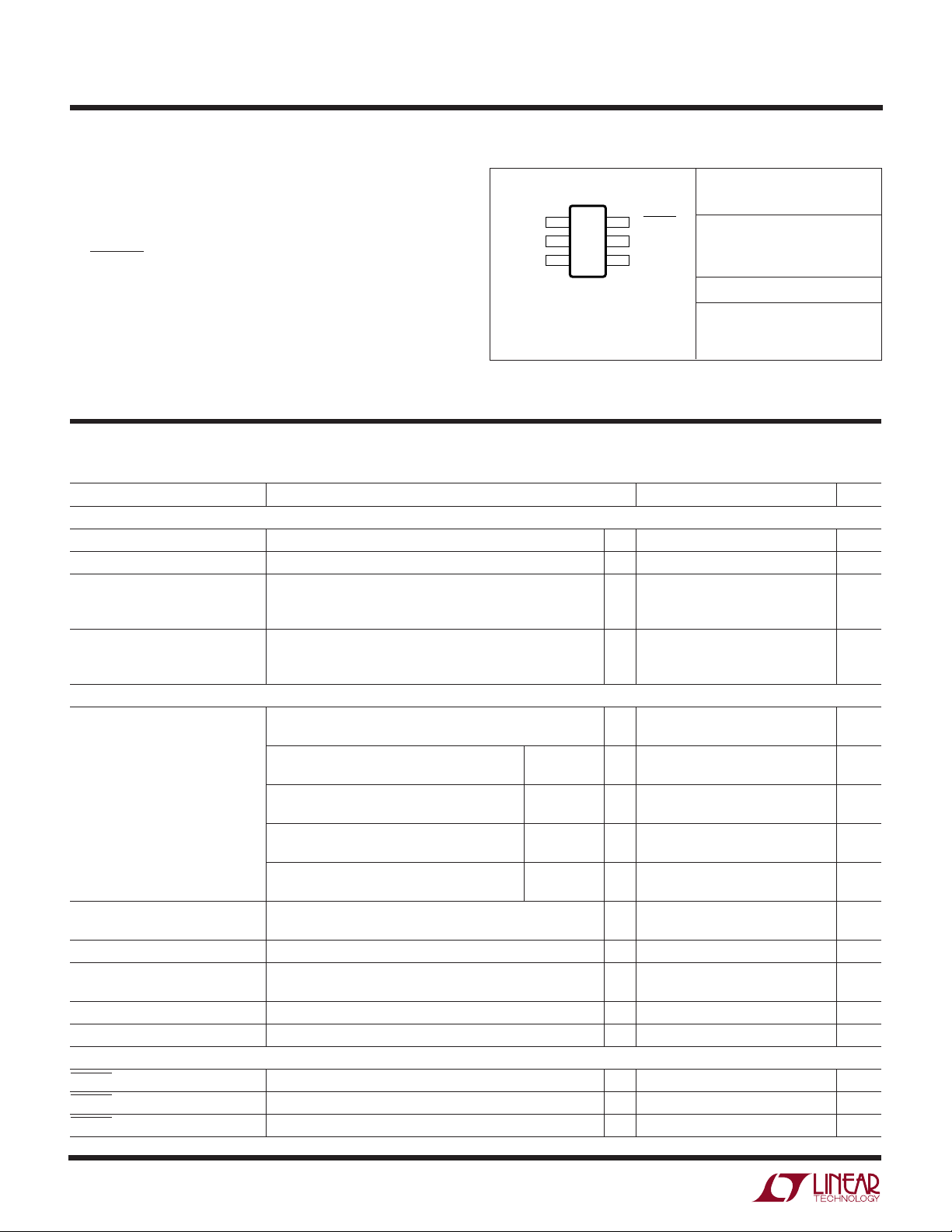
TYPICAL PERFOR A CE CHARACTERISTICS
Quiescent Supply Current vs
Supply Voltage
3.5
TA = 25°C
= V
V
LOGIC
3.0
2.5
2.0
1.5
1.0
SUPPLY CURRENT (µA)
0.5
BATT
V
= 1.5V
TH.A
V
TH.A
= 0V
Quiescent Supply Current vs
Temperature
3.5
V
= V
LOGIC
= 3V
V
BATT
3.0
2.5
2.0
1.5
1.0
SUPPLY CURRENT (µA)
0.5
TH.A
= 1.5V
Threshold Voltage vs Threshold
Adjust Voltage
3.5
3.0
THRESHOLD VOLTAGE (V)
0
0.5 1.0 1.5 2.0 2.5 3.0 3.5 4.0 4.5 5.0 5.5 6.0
SUPPLY VOLTAGE (V)
Available Hysteresis vs
Threshold Voltage
750
500
250
AVAILABLE HYSTERESIS (mV)
0
2.5
2.75 3.0
LOW BATTERY THRESHOLD VOLTAGE (V)
1998 G01
1998 G04
3.25
0
–50 –30 –10 10 30 50 70 90
TEMPERATURE (°C)
Threshold Voltage Error vs
Temperature
1.0
0.9
V
SET BY 1%
0.8
0.7
0.6
V
0.5
% ERROR
0.4
0.3
0.2
0.1
0
–45 15 55
1V
TH.A =
THRESHOLD = 3V
–25 –5
TEMPERATURE (°C)
TH.A
EXTERNAL R,
THRESHOLD = 3V
V
SHORTED
TH.A
TO GROUND,
THRESHOLD = 2.5V
35 75 95
1998 G02
1998 G05
2.5
0
0.5 1.0
THRESHOLD ADJUST VOLTAGE (V)
Input Current vs Temperature
10000
1000
(pA)
H.A
, V
100
TH.A
10
1
INPUT CURRENT V
0.1
45 65
35
55
75
TEMPERATURE (°C)
1.5
1998 G03
VIN = 1.5V
VIN = 1V
VIN = 0.5V
105
85 125
115
95
1998 G06
1998f
3
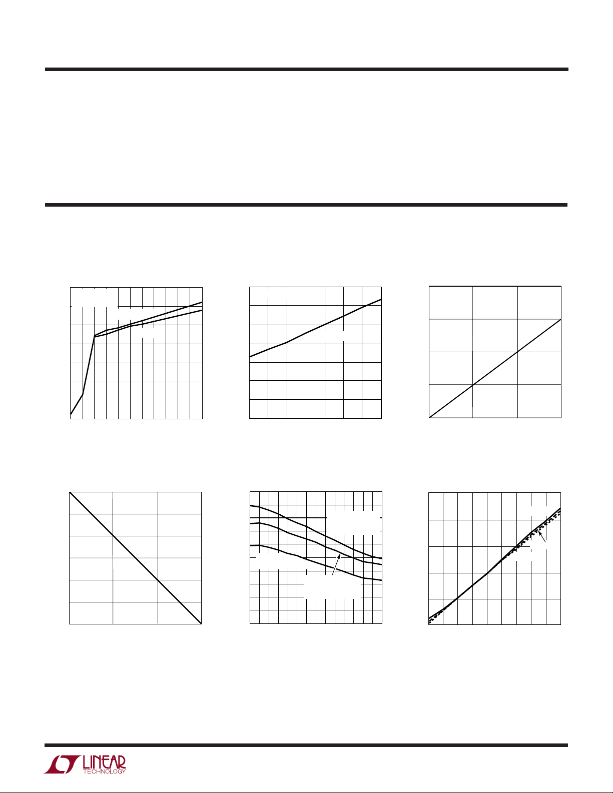
Page 4

LTC1998
SUPPLY VOLTAGE (V)
1.0 1.5 2.5 3.5 4.5 5.5
CURRENT (mA)
120
100
80
60
40
20
0
2.0 3.0 4.0 5.0
1998 G09
6.0
SOURCE CURRENT,
BATTLO SHORTED TO GND
SINK CURRENT,
BATTLO SHORTED
TO V
LOGIC
TA = 25°C
V
BATT
= V
LOGIC
UW
TYPICAL PERFOR A CE CHARACTERISTICS
Output Low Voltage vs Load
Current
0.6
TA = 25°C
= V
V
LOGIC
0.4
TA = 25°C
0.2
OUTPUT VOLTAGE (V)
0
1
= 3V
BATT
234
OUTPUT SINK CURRENT (mA)
U
TA = 85°C
TA = –40°C
5
1998 G07
UU
Output High Voltage vs Load
Current
0
(mV)
–50
BATT
–100
TA = –40°C
–150
–200
OUTPUT VOLTAGE RELATIVE TO V
–250
1
TA = 25°C
TA = 25°C
V
= V
LOGIC
BATT
234
OUTPUT SOURCE CURRENT (mA)
PI FU CTIO S
BATT (Pin 1): Battery Voltage to be monitored. Supply
current is also drawn from this pin. Board layout should
connect this pin to the battery(+) terminal, through a trace
that does not conduct load current.
GND (Pin 2): Ground should be connected to the battery
(–) terminal through a trace that does not conduct load
return current.
V
(Pin 3): Threshold Adjust Pin. Adjusts the low
TH.A
battery threshold voltage, V
V
can be supplied by a voltage source or a resistor
TH.A
BATT.Th
divider.
= 2.5V + (V
TH.A
/2).
Output Short-Circuit Current vs
Supply Voltage
TA = 85°C
TA = 25°C
TA = –40°C
TA = 85°C
BATT = 3V
BATT = 5V
5
1998 G08
V
(Pin 4): Hysteresis Adjust. Hysteresis threshold
H.A
voltage V
voltage source or resistor divider. V
programmed to a higher potential than V
voltage, V
V
LOGIC
= 2.5V + (V
TH2
= V
HYST
TH2
H.A
– V
/2). V
BATT.Th
can be supplied by a
H.A
must always be
H.A
. Hysteresis
TH.A
.
(Pin 5): Positive Supply Voltage for Output Driver.
This voltage can be driven from an external logic supply or
tied to BATT.
BATTLO (Pin 6): Output of Comparator. Low for BATT <
V
BATT.Th
guaranteed for V
(low battery threshold voltage). Output state
≥ 1.5V.
BATT
QUICK DESIG GUIDE
How to Calculate the External Resistor Values
The LTC1998 is a low battery warning indicator and is
especially designed for monitoring the voltage of singlecell Lithium-Ion batteries. The LTC1998 compares its
supply pin (BATT) to an accurate internal reference; if the
battery voltage falls below the programmed low battery
4
U
threshold voltage of the LTC1998, the battery low pin
(BATTLO) will change state, from high to low, to indicate
a low battery condition. The low battery threshold voltage
is programmed via the voltage threshold adjust pin (V
A hysteresis adjust pin (V
) will add hysteresis to the
H.A
TH.A
).
programmed value of the low battery threshold voltage.
1998f
Page 5

U
QUICK DESIG GUIDE
LTC1998
Typical Application
Table 1: Design Equations for R1, R2, R3, Figure 1
Choose desired values for:
• V
• V
BATT.Th
HYST
: Low Battery Threshold Voltage
: Hysteresis Voltage
• IR: Max Allowable Resistor Current
Solve:
V
42
V
5
+
.
.
.
I
R
1
R
11
RRRR
RR
RR
RR RR
=++ =
TOTAL
=
1
=
2
=
312
123
•–
TOTAL
TOTAL
TOTAL
VV
BATT Th HYST
V
5
•––
V
BATT Th
––
Example 1: A system using a 4.2V (fully charged) LithiumIon battery requires a low battery threshold of 2.7V,
100mV hysteresis and can allow up to 4.2µA maximum
resistor current.
R
= 1MΩ, R1 = 786k, R2 = 66k and R3 = 148k
TOTAL
Choose standard 1% values.
R1 = 787k, R2 = 66.5k, R3 = 147k
1.5V TO 4.2V
0.1µF
R1
+
1%
4
V
R2
1%
Li-Ion
R3
1%
Figure 1. Low Battery Threshold Detector with Hysteresis
H.A
3
V
TH.A
1
BATT
V
LTC1998
BATTLO
GND
2
REGULATOR
LOGIC
5
6
V
LOGIC
µP
1998 F01
WUUU
APPLICATIO S I FOR ATIO
LOW BATTERY THRESHOLD VOLTAGE AND
HYSTERESIS ADJUST
Low Battery Threshold Voltage Adjustment, Pin 3
The low battery threshold voltage is the battery voltage
which will trip the (BATTLO) pin high to low. It should be
adjusted via the threshold adjust pin (V
input impedance pin that senses an externally applied
voltage and programs the low battery threshold voltage
(V
BATT.Th
). The V
pin is designed to accommodate
TH.A
voltages from 0V to 1.5V with respect to ground. This
allows the low battery threshold voltage to be set to any
voltage between 2.5V and 3.25V, that is:
V
()
VV
BATT Th
.
=+25
TH A..
2
). This is a high
TH.A
For instance, if the applied voltage at pin 3, V
, is 1V the
TH.A
LTC1998 will indicate a low battery condition when the
battery voltage pin (BATT) falls below 3V.
The voltage at the threshold adjust pin (V
) can be set
TH.A
with any voltage source. This pin allows a continuous time
adjustment, that is, the low battery threshold voltage may
be changed at any time. The high input impedance of the
V
pin allows the use of a high valued resistive divider
TH.A
(to minimize current drain) from the battery to set the
battery low threshold voltage, Figure 2.
3
BATT
V
TH.A
LTC1998
1
2
1998 F02
+
R1
Li-Ion
R2
Figure 2. Resistor Divider Sets Threshold
1998f
5
Page 6

LTC1998
1998 F03
LTC1998
R1
R2
R3
V
H.A
V
TH.A
BATT
+
Li-Ion
1
4
3
WUUU
APPLICATIO S I FOR ATIO
The simple calculations of resistor values R1 and R2 are
illustrated below. Set a value for R1 + R2. This value will
affect the max amount of current drawn from the battery
when fully charged. For instance if R1 + R2 = 1M the
resistive divider will draw 4.1µA when the battery voltage
is 4.1V. Set the desired value of V
BATT.Th
(this value should
be between 2.5V and 3.25V) that is the value of the battery
voltage that will trip the internal circuitry of the LTC1998
and change the state of the battery low pin (BATTLO).
Solve for R R R
112
() –
V
BATT Th
V
5
1=+
.
Example: A Lithium-Ion battery is monitored and a battery
low signal should be issued when it discharges to 2.85V,
that is, V
BATT.Th
= 2.85V; if (R1 + R2) = 1M, then
R1 = 754.38k and R2 = 245.62k. Choose the closest 1%
value of R1 = 750k and R2 = 243k. Calculate the practical
value for V
BATT.Th
as it will be slightly different from 2.85V,
due to the use of standard 1% resistor values.
+
12
VV
BATT Th.
RR
()
++
112
RRR
=5
.=
2 849
V
The above low battery threshold of 2.849V is guaranteed
to within 1% even though 1% resistors are used to
program the V
For sake of completeness, the voltage at Pin 3 (V
be easily calculated by V
0.6972V (when V
voltage applied to Pin 3.
TH.A
= V
BATTERY
TH.A
= V
BATT.Th
BATT.Th
TH.A
(R2/(R1 + R2) =
).
) can
The programming of the hysteresis threshold adjust pin
(V
) is similar to the programming of the voltage thresh-
H.A
old adjust pin (V
) already described in the previous
TH.A
paragraph. Pin 4 effectively adjusts the threshold voltage
at which the low battery pin (BATTLO) changes state from
low to high. This threshold (V
V
()
VV
THHA2
25
=+.
.
2
) is defined as:
TH2
The actual hysteresis voltage is:
V
HYST
= V
TH2
– V
BATT.Th
It is imperative that the hysteresis threshold adjust voltage
at Pin 4 be set to a higher voltage than the low battery
threshold adjust voltage at Pin 3, at all times, to avoid
oscillation at the BATTLO output pin. The hysteresis
threshold adjust pin may be set with a voltage source or
with a resistor divider, just as with the low battery threshold adjust pin.
Combined Control of Threshold and Hysteresis
If a resistor divider is desired, then both threshold adjust
dividers can be combined in order to save current. This
simple technique also guarantees that the hysteresis threshold adjust voltage at Pin 4 is higher than the voltage at the
V
pin, Figure 3.
TH.A
Hysteresis Adjustment, Pin 4.
The LTC1998 has an adjustable hysteresis ranging from
10mV to 0.75V. A large hysteresis is useful in the event
that a low battery signal at the LTC1998’s BATTLO pin
causes the system to shed some battery load, thus inducing system confusion as the partially loaded battery recovers and changes the status of Pin 6 (BATTLO). The 2.5V to
3.25V programming window of low battery threshold
voltage includes the hysteresis. If, for instance, the low
battery threshold voltage is set to 2.5V, 750mV hysteresis
can be added on top of the 2.5V. If the low battery
threshold voltage is set to 3.15V, only 100mV hysteresis
can be applied.
6
Figure 3. Combined Resistor Divider
The calculation of the resistor values R1, R2 and R3 is
quite straightforward and similar to the procedure outlined in the previous paragraph.
Choose a value for the sum of R1 + R2 + R3 as well as the
values for low battery threshold and hysteresis.
Solve for resistor R1:
1998f
Page 7

WUUU
APPLICATIO S I FOR ATIO
LTC1998
RRRR
1123
=++
()–
5
V
TH
V
1
2
Solve for the sum of
V
()( ) –
RR RR R
12 123
V
BATT Th
5
1+=++
.
then solve for R2 and R3.
Example: A system needs to detect a low battery voltage of
3V (V
BATT.Th
= 3V) with 250mV hysteresis (V
= 3.25V).
TH2
Set the value of the resistor divider (R1 + R2 + R3) = 1M.
R1 = 539k, R1 + R2 = 667k, R2 = 128k, R3 = 333k. Choose
the closest 1% values, that is 536k, 332k, 127k. Figure 4
graphically shows the function of the LTC1998 as
described above.
VERSATILE OUTPUT DRIVER
V
, BATTLO (Pins 5,6)
LOGIC
The LTC1998 uses a CMOS push-pull output stage to drive
the low battery output signal. This output pin (BATTLO)
has a separate supply pin, (V
) that can be used to
LOGIC
provide an output voltage rail matching the VDD logic of
microprocessors. The V
lower than the voltage at the BATT pin. The V
also be tied to a voltage higher than V
pin may be tied to a voltage
LOGIC
LOGIC
via a series
BATT
pin may
resistor greater than 10kΩ. The output will then act as an
open-drain device.
In a given application, if it is possible for BATTLO to be
shorted to GND or a supply, a series resistor should be
added to limit the short-circuit current to 5mA.
3.25V
PROGRAMMED
HYSTERESIS
THRESHOLD
PROGRAMMED
LOW BATT
THRESHOLD
2.50V
V
LOGIC
BATTLO
PROGRAMMABLE
THRESHOLD RANGE
BATTERY
VOLTAGE
Figure 4. LTC1998 Function Plot
HYSTERESIS
BATTERY VOLTAGE
RECOVERS UNDER
REDUCED LOAD
1998 F04
PACKAGE DESCRIPTIO
3.85 MAX
2.62 REF
NOTE:
1. DIMENSIONS ARE IN MILLIMETERS
2. DRAWING NOT TO SCALE
3. DIMENSIONS ARE INCLUSIVE OF PLATING
4. DIMENSIONS ARE EXCLUSIVE OF MOLD
FLASH AND METAL BURR
5. MOLD FLASH SHALL NOT EXCEED 0.254mm
6. JEDEC PACKAGE REFERENCE IS MO-193
0.20 BSC
Information furnished by Linear Technology Corporation is believed to be accurate and reliable.
However, no responsibility is assumed for its use. Linear Technology Corporation makes no representation that the interconnection of its circuits as described herein will not infringe on existing patent rights.
U
6-Lead Plastic TSOT-23
(Reference LTC DWG # 05-08-1636)
0.62
MAX
RECOMMENDED SOLDER PAD LAYOUT
PER IPC CALCULATOR
DATUM ‘A’
0.95
REF
0.30 – 0.50 REF
S6 Package
1.22 REF
1.4 MIN
2.80 BSC
0.09 – 0.20
(NOTE 3)
1.50 – 1.75
(NOTE 4)
1.00 MAX
0.95 BSC
0.80 – 0.90
PIN ONE ID
2.90 BSC
(NOTE 4)
1.90 BSC
0.30 – 0.45
6 PLCS (NOTE 3)
0.01 – 0.10
S6 TSOT-23 0302
1998f
7
Page 8

LTC1998
4
3
2
1
5
6
R4
909k
1%
R5
6.98k
1%
R6
76.8k
1%
LTC1998
V
H.A
V
TH.A
BATT
V
LOGIC
BATTLO
GND
4
3
2
1
5
6
R1
619k
1%
R2
6.04k
1%
R3
383k
1%
LTC1998
V
H.A
V
TH.A
BATT
V
LOGIC
BATTLO
GND
V
IN
NC
V
+
R7
1M
2N7002
WINDOW LOW THRESHOLD = 2.6V
HYSTERESIS = 10mV
WINDOW HIGH THRESHOLD = 3.1V
HYSTERESIS = 10mV
1998 TA06
V
OUT
V
OUT
= V+ WHEN
2.6V ≤ V
IN
≤ 3.1V
TYPICAL APPLICATIO S
U
Single Li-Ion Cell Low Battery Detector
=
V
BATT
1.5V TO 4.2V
R1
+
1%
R2
1%
Li-Ion
R3
1%
0.1µF
4
3
V
H.A
V
TH.A
1
BATT
V
LTC1998
BATTLO
GND
2
REGULATOR
5
LOGIC
6
Micropower 2.9V VCC Threshold
Detector with 15mV Hysteresis
3.3V
R1
715k
1%
R2
9.09k
1%
R3
274k
1%
4
3
V
H.A
V
TH.A
1
BATT
V
LTC1998
BATTLO
GND
2
LOGIC
5
6
V
LOGIC
1V TO 5V
OUT
Backup Battery Switchover Circuit
=
µP
1998 TA01
2.5V TO 4.2V
R1
787k
+
1%
4
R2
68.1k
Li-Ion
1%
3
R3
147k
1%
SWITCHES TO BACKUP BATTERY WHEN PRIMARY FALLS BELOW 2.7V.
SWITCHES BACK TO PRIMARY WHEN VOLTAGE RECOVERS TO ≥ 2.8V
V
H.A
V
TH.A
1
BATT
V
LOGIC
LTC1998
BATTLO
GND
2
5
6
BAT54C
R4
1M
BAT54C
MBRM120
+
V
OUT
Si2301
Si2301
3V
BACKUP
BATTERY
1998 TA04
High Accuracy Window Comparator
with Dual Hysteresis
LOW THRESHOLD = 2.9V
HYSTERESIS = 15mV
1998 TA03
Low Battery Load Reduction Circuit
R1
787k
+
1%
4
V
H.A
R2
68.1k
Li-Ion
1%
3
V
TH.A
R3
147k
RELATED PARTS
PART NUMBER DESCRIPTION COMMENTS
1%
LOW THRESHOLD = 2.7V
HYSTERESIS = 100mV
LTC1440/LTC1540 Micropower Comparator with 1% Reference 1.182V ±1% Reference, ±10mV (Max) Input Offset
LTC1441/LTC1442 Micropower Dual Comparator with 1% Reference 1.182V ±1% Reference (LTC1442)
LTC1443/LTC1444/LTC1445 Micropower Quad Comparator with 1% Reference LTC1443 has 1.182V Reference, LTC1444/LTC1445 have 1.221V
8
Linear Technology Corporation
1630 McCarthy Blvd., Milpitas, CA 95035-7417
(408) 432-1900 ● FAX: (408) 434-0507
1
BATT
V
LTC1998
BATTLO
GND
2
REGULATOR
LOGIC
5
6
Si2301
NONCRITICAL
CIRCUITRY
●
www.linear.com
CRITICAL
CIRCUITRY
1998 TA05
Reference and Adjustable Hysteresis
LT/TP 0802 2K • PRINTED IN USA
LINEAR TECHNOLOGY CORPORATION 2001
1998f
 Loading...