

Page 1
FEATURES
■
Dual MOSFET Drivers in SO-8 Package
or Single MOSFET Driver in MSOP Package
■
1GΩ Electrical Isolation Between the Dual Drivers
Permits High/Low Side Gate Drive
■
1.5A Peak Output Current
■
16ns Rise/Fall Times at VCC = 12V, CL = 1nF
■
Wide VCC Range: 4.5V to 13.2V
■
CMOS Compatible Inputs with Hysteresis,
Input Thresholds are Independent of V
■
Driver Input Can Be Driven Above V
■
Undervoltage Lockout
■
Thermal Shutdown
CC
CC
U
APPLICATIO S
■
Power Supplies
■
High/Low Side Drivers
■
Motor/Relay Control
■
Line Drivers
■
Charge Pumps
LTC1693
High Speed
Single/Dual MOSFET Drivers
U
DESCRIPTIO
The LTC®1693 family drives power MOSFETs at high
speed. The 1.5A peak output current reduces switching
losses in MOSFETs with high gate capacitance.
The LTC1693-1 contains two noninverting drivers. The
LTC1693-2 contains one noninverting and one inverting
driver. The LTC1693-1 and LTC1693-2 drivers are electrically isolated and independent. The LTC1693-3 is a single
driver with an output polarity select pin.
The LTC1693 has VCC independent CMOS input thresholds with 1.2V of typical hysteresis. The LTC1693 can
level-shift the input logic signal up or down to the rail-torail VCC drive for the external MOSFET.
The LTC1693 contains an undervoltage lockout circuit and
a thermal shutdown circuit. Both circuits disable the
external N-channel MOSFET gate drive when activated.
The LTC1693-1 and LTC1693-2 come in an 8-lead SO package. The LTC1693-3 comes in an 8-lead MSOP package.
, LTC and LT are registered trademarks of Linear Technology Corporation.
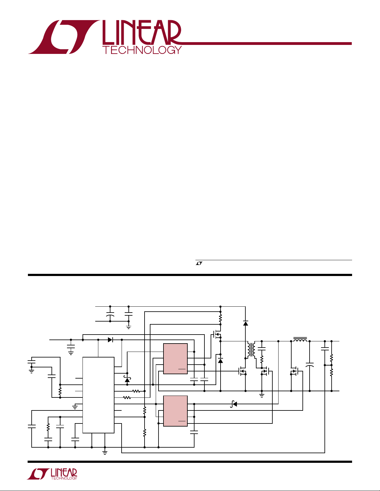
TYPICAL APPLICATIO
V
IN
C11
0.1µF
1800pF
C10
0.1µF
C14
3300pF
NPO
48VDC
±10%
RETURN
12V
C9
5%
R9
12k
R5
2.49k
1%
C12
100pF
C5
1µF
10
1
2
4
3
5
6
7
C15
0.1µF
SYNC
5V
REF
SL/ADJ
C
T
I
AVG
SS
V
C
V
REF
12V
LT1339
8
+
MURS120
17
IN
BOOST
SENSE
SENSE
PHASE
RUN/SHDN
PGNDSGND
15
C1
330µF
63V
D2
TG
TS
+
–
BG
V
FB
20
19
18
11
12
16
14
13
9
U
R7 100Ω
C2
1.5µF
63V
BAT54
R6 100Ω
Two Transistor Foward Converter
LTC1693CS8-2
R8
301k
1%
R10
10k
1%
1
IN1
2
GND1
3
IN2
4
GND2
LTC1693CS8-2
1
IN1
2
GND1
3
IN2
4
GND2
V
OUT1
V
OUT2
V
OUT1
V
OUT2
8
CC1
7
6
CC2
5
C7
1µF
8
CC1
7
6
CC2
5
C13
1µF
C8
1µF
R1
0.068Ω
Q1
MTD20NO6HD
D1
MURS120
T1
13:2
••
D3
MURS120
Si4420
Q3
MTD20NO6HD
D4
MBRO530T1
C1: SANYO 63MV330GX
C2: WIMA SMD4036/1.5/63/20/TR
C6: KEMET T510X477M006AS (×8)
L1: GOWANDA 50-318
T1: GOWANDA 50-319
L1
1.5µH
C3
4700pF
25V
R2
5.1Ω
Q4
Si4420
Q2
×2
C4
0.1µF
C6
+
470µF
6.3V
×8
1693 TA01
R3
249Ω
1%
R4
1.24k
1%
V
OUT
1.5V/15A
RETURN
1
Page 2
LTC1693
WW
W
U
ABSOLUTE MAXIMUM RATINGS
(Note 1)
Supply Voltage (VCC) .............................................. 14V
Inputs (IN, PHASE)................................... –0.3V to 14V
Driver Output................................. –0.3V to VCC + 0.3V
GND1 to GND2 (Note 5) ..................................... ±100V
U
W
U
PACKAGE/ORDER INFORMATION
TOP VIEW
IN1
IN1
1
GND1
2
IN2
3
GND2
4
S8 PACKAGE
8-LEAD PLASTIC SO
T
= 150°C, θJA = 135°C/W
JMAX
ORDER PART
NUMBER
V
8
CC1
OUT1
7
V
6
CC2
OUT2
5
S8 PART
MARKING
ORDER PART
NUMBER
1
GND1
2
IN2
3
GND2
4
8-LEAD PLASTIC SO
T
= 150°C, θJA = 135°C/W
JMAX
S8 PACKAGE
Junction Temperature.......................................... 150°C
Operating Ambient Temperature Range.......0°C to 70°C
Storage Temperature Range................. –65°C to 150 °C
Lead Temperature (Soldering, 10 sec)..................300°C
TOP VIEW
V
8
CC1
OUT1
7
V
6
CC2
OUT2
5
S8 PART
MARKING
PHASE
GND
ORDER PART
NUMBER
TOP VIEW
IN
1
NC
2
3
4
MS8 PACKAGE
8-LEAD PLASTIC MSOP
T
= 150°C, θJA = 200°C/W
JMAX
8
7
6
5
MS8 PART
MARKING
V
CC
OUT
NC
NC
LTC1693-1CS8 16931
Consult factory for Industrial and Military grade parts.
LTC1693-2CS8
ELECTRICAL CHARACTERISTICS
The ● denotes specifications which apply over the full operating
16932
LTC1693-3CMS8 LTEB
temperature range, otherwise specifications are at TA = 25°C. VCC = 12V, unless otherwise noted.
SYMBOL PARAMETER CONDITIONS MIN TYP MAX UNITS
V
CC
I
CC
I
CC(SW)
Input
V
IH
V
IL
I
IN
V
PH
I
PH
Output
V
OH
V
OL
R
ONL
R
ONH
I
PKL
I
PKH
Supply Voltage Range 4.5 13.2 V
Quiescent Current LTC1693-1, LTC1693-2, IN1 = IN2 = 0V (Note 2) ● 400 720 1100 µA
LTC1693-3, PHASE = 12V, IN = 0V
Switching Supply Current LTC1693-1, LTC1693-2, C
LTC1693-3, C
High Input Threshold ● 2.2 2.6 3.1 V
Low Input Threshold ● 1.1 1.4 1.7 V
Input Pin Bias Current ● ±0.01 ±10 µA
PHASE Pin High Input Threshold (Note 3) ● 4.5 5.5 6.5 V
PHASE Pin Pull-Up Current PHASE = 0V (Note 3) ● 10 20 45 µA
High Output Voltage I
Low Output Voltage I
Output Pull-Down Resistance 2.85 Ω
Output Pull-Up Resistance 3.00 Ω
Output Low Peak Current 1.70 A
Output High Peak Current 1.40 A
= –10mA ● 11.92 11.97 V
OUT
= 10mA ● 30 75 mV
OUT
= 4.7nF, fIN = 100kHz ● 7.2 10 mA
OUT
= 4.7nF, fIN = 100kHz ● 14.4 20 mA
OUT
● 200 360 550 µA
2
Page 3
LTC1693
ELECTRICAL CHARACTERISTICS
The ● denotes specifications which apply over the full operating
temperature range, otherwise specifications are at TA = 25°C. VCC = 12V, unless otherwise noted.
SYMBOL PARAMETER CONDITIONS MIN TYP MAX UNITS
Switching Timing (Note 4)
t
RISE
t
FALL
t
PLH
t
PHL
Output Rise Time C
Output Fall Time C
Output Low-High Propagation Delay C
Output High-Low Propagation Delay C
= 1nF ● 17.5 35 ns
OUT
C
= 4.7nF ● 48.0 85 ns
OUT
= 1nF ● 16.5 35 ns
OUT
C
= 4.7nF ● 42.0 75 ns
OUT
= 1nF ● 38.0 70 ns
OUT
= 4.7nF ● 40.0 75 ns
C
OUT
= 1nF ● 32 70 ns
OUT
= 4.7nF ● 35 75 ns
C
OUT
Driver Isolation
R
ISO
Note 1: Absolute Maximum Ratings are those values beyond which the life
of a device may be impaired.
Note 2: Supply current is the total current for both drivers.
GND1-GND2 Isolation Resistance LTC1693-1, LTC1693-2 GND1-to-GND2 Voltage = 75V ● 0.075 1 GΩ
Note 4: All AC timing specificatons are guaranteed by design and are not
production tested.
Note 5: Only applies to the LTC1693-1 and LTC1693-2.
Note 3: Only the LTC1693-3 has a PHASE pin.
UW
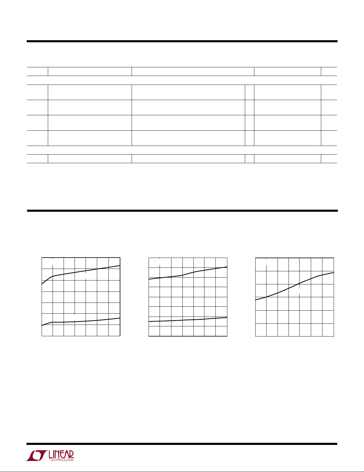
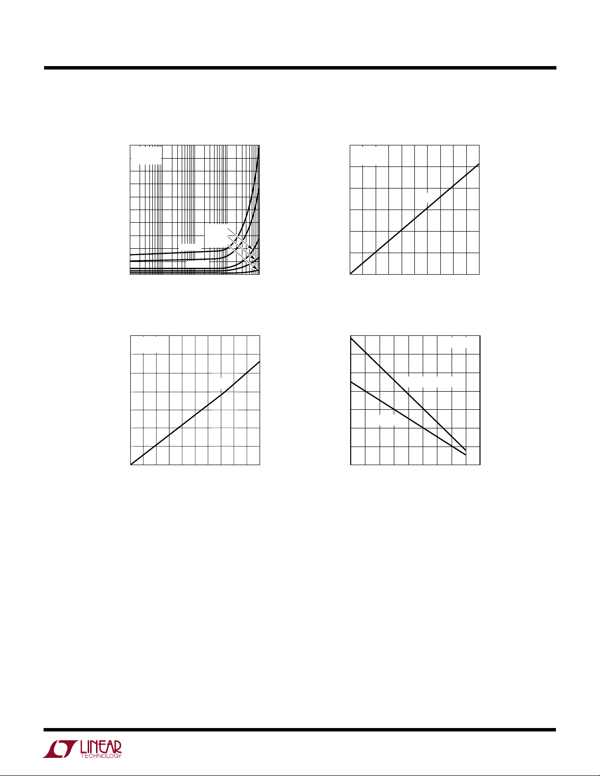
TYPICAL PERFOR A CE CHARACTERISTICS
IN Threshold Voltage vs V
2.75
TA = 25°C
2.50
2.25
2.00
1.75
1.50
INPUT THRESHOLD VOLTAGE (V)
1.25
1.00
5
67
V
IL
810
VCC (V)
CC
V
IH
91112
1693 G01
IN Threshold Voltage
vs Temperature
3.00
VCC = 12V
2.75
2.50
2.25
2.00
1.75
1.50
INPUT THRESHOLD VOLTAGE (V)
1.25
1.00
–25 0 50
–50
25
TEMPERATURE (°C)
V
IH
V
IL
75 100 125
1693 G02
IN Threshold Hysteresis
vs Temperature
1.4
VCC = 12V
1.3
1.2
V
IH-VIL
1.1
1.0
0.9
INPUT THRESHOLD HYSTERESIS (V)
0.8
–25 0 50 100 125
–50
25 75
TEMPERATURE (°C)
1693 G03
3
Page 4
LTC1693
UW
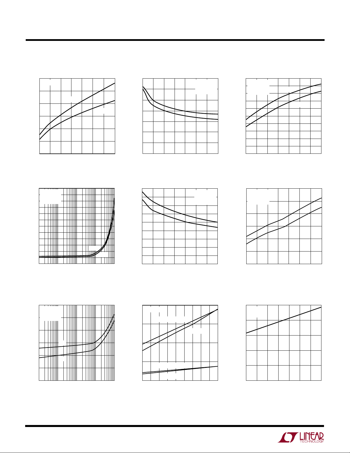
TYPICAL PERFOR A CE CHARACTERISTICS
PHASE Threshold Voltage vs V
6
TA = 25°C
5
V
4
3
2
1
PHASE THRESHOLD VOLTAGE (V)
0
5
67
Rise/Fall Time vs C
120
TA = 25°C
= 12V
V
CC
= 100kHz
f
100
IN
80
60
TIME (ns)
40
20
0
1 100 1000 10000
PH(H)
810
VCC (V)
10
(pF)
C
OUT
V
91112
OUT
t
RISE
PH(L)
t
FALL
CC
1693 G04
1693 G07
Rise/Fall Time vs V
24
22
20
18
16
TIME (ns)
14
12
10
5
67
55
50
45
40
35
30
TIME (ns)
25
20
15
10
t
PHL
6891110 12
5
CC
t
RISE
t
FALL
91112
810
VCC (V)
t
PLH
7
VCC (V)
TA = 25°C
C
OUT
= 100kHz
f
IN
CC
TA = 25°C
C
OUT
= 100kHz
f
IN
= 1nF
1693 G05
= 1nF
1693 G08
Rise/Fall Time vs Temperature
20
VCC = 12V
19
C
= 1nF
18
17
16
15
TIME (ns)
14
13
12
11
10
–50
OUT
= 100kHz
f
IN
–25
0
TEMPERATURE (°C)
t
RISE
50
25
Propagation Delay vs TemperaturePropagation Delay vs V
50
VCC = 12V
= 1nF
C
OUT
= 100kHz
45
f
IN
40
t
–50
PLH
–25 0
t
PHL
50
25 75
TEMPERATURE (°C)
35
TIME (ns)
30
25
20
t
FALL
75
125
100
1693 G06
100 125
1693 G09
Propagation Delay vs C
50
TA = 25°C
= 12V
V
CC
= 100kHz
f
IN
40
t
PLH
TIME (ns)
30
20
1 100 1000 10000
t
PHL
10
C
(pF)
OUT
4
OUT
1693 G10
Output Saturation Voltage
vs Temperature
200
VCC = 12V
150
100
50
OUTPUT SATURATION VOLTAGE (mV)
0
–55
VOH (50mA) wrt V
VOH (10mA) wrt V
VOL (10mA)
–35 –15 5 25
TEMPERATURE (°C)
CC
VOL (50mA)
CC
45 65 85 105 125
1693 G11
Quiescent Current
vs VCC (Single Driver)
350
TA = 25°C
= 0V
V
IN
300
250
200
QUIESCENT CURRENT (µA)
150
100
56
7
8
VCC (V)
9
10
11
12
1693 G12
Page 5
UW
TYPICAL PERFOR A CE CHARACTERISTICS
Switching Supply Current
vs C
(Single Driver)
OUT
100
TA = 25°C
90
V
= 12V
CC
80
70
60
50
40
30
20
SWITCHING SUPPLY CURRENT (mA)
10
0
1 100 1000 10000
10
750kHz
500kHz
C
OUT
200kHz
100kHz
25kHz
(pF)
1693 G13
300
250
200
150
(mV)
OL
V
100
50
0
VOL vs Output Current
VCC = 12V
= 25°C
T
A
V
OL
20 40 60 80
OUTPUT CURRENT (mA)
LTC1693
10010030507090
1693 G14
VOH vs Output Current
350
TA = 25°C
= 12V
V
CC
300
250
200
(mV)
OH
150
V
100
50
0
0
30
20
10
OUTPUT CURRENT (mA)
40
50
60 80
Thermal Derating Curves
1400
1200
1000
V
OH
90
1693 G15
100
70
800
600
400
POWER DISSIPATION (mW)
200
LTC1693-3
0
–35 –15 5 25 45 125
–55
LTC1693-1/LTC1693-2
AMBIENT TEMPERATURE (°C)
TJ = 125°C
65 85 105
1693 G16
5
Page 6
LTC1693
UUU
PIN FUNCTIONS
SO-8 Package (LTC1693-1, LTC1693-2)
IN1, IN2 (Pins 1, 3):
Driver Inputs. The inputs have V
CC
independent thresholds with 1.2V typical hysteresis to
improve noise immunity.
GND1, GND2 (Pins 2, 4): Driver Grounds. Connect to a
low impedance ground. The VCC bypass capacitor should
connect directly to this pin. The source of the external
MOSFET should also connect directly to the ground pin.
This minimizes the AC current path and improves signal
integrity. The ground pins should not be tied together if
isolation is required between the two drivers of the
LTC1693-1 and the LTC1693-2.
OUT 1, OUT2 (Pins 5, 7): Driver Outputs. The LTC16931’s outputs are in phase with their respective inputs (IN1,
IN2). The LTC1693-2’s topside driver output (OUT1) is in
phase with its input (IN1) and the bottom side driver’s
output (OUT2) is opposite in phase with respect to its input
pin (IN2).
V
, V
CC1
(Pins 6, 8): Power Supply Inputs.
CC2
MSOP Package (LTC1693-3)
IN (Pin 1):
Driver Input. The input has VCC independent
thresholds with hysteresis to improve noise immunity.
NC (Pins 2, 5, 6): No Connect.
PHASE (Pin 3): Output Polarity Select. Connect this pin to
VCC or leave it floating for noninverting operation. Ground
this pin for inverting operation. The typical PHASE pin
input current when pulled low is 20µA.
GND (Pin 4): Driver Ground. Connect to a low impedance
ground. The VCC bypass capacitor should connect directly
to this pin. The source of the external MOSFET should also
connect directly to the ground pin. This minimizes the AC
current path and improves signal integrity.
OUT (Pin 7): Driver Output.
VCC (Pin 8): Power Supply Input.
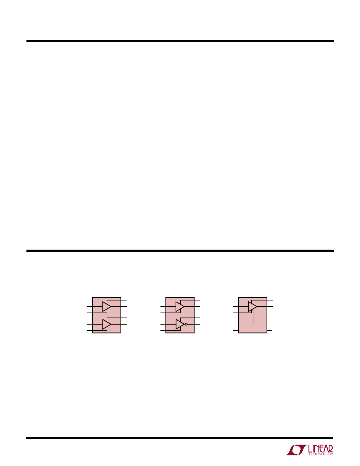
W
BLOCK DIAGRA SM
1
IN1
2
GND1
3
IN2
4
GND2
LTC1693-1
DUAL NONINVERTING DRIVER
8
V
CC1
7
OUT1
6
V
CC2
5
OUT2
1
IN1
2
GND1
3
IN2
4
GND2
TOPSIDE NONINVERTING DRIVER
AND BOTTOM SIDE INVERTING DRIVER
LTC1693-2
8
V
CC1
7
OUT1
6
V
CC2
5
OUT2
1
IN
4
GND
3
PHASE
2
NC
SINGLE DRIVER WITH
POLARITY SELECT
LTC1693-3
8
V
CC
7
OUT
6
NC
5
NC
1693 BD
6
Page 7

TEST CIRCUITS
1/2 LTC1693-1 OR 1/2 LTC1693-2
87V
LTC1693
V
CC1
8
12V
P-P
75V
1/2 LTC1693-1 OR 1/2 LTC1693-2
12V
4.7nF
4.7nF
4.7µF 0.1µF
4.7µF 0.1µF
1693 TC03
A
+
75V
–
IN1
1
GND1
2
IN2
3
GND2
4
75V High Side Switching Test LTC1693-1, LTC1693-2 Ground Isolation Test
VCC = 12V
4.7µF 0.1µF
OUTIN
5V
t
RISE/FALL
< 10ns
1nF OR 4.7nF
OUT1
V
CC2
OUT2
7
6
5
1693 TC02
UWW
TI I G DIAGRA
INPUT
NONINVERTING
OUTPUT
INVERTING
OUTPUT
AC Parameter Measurements
INPUT RISE/FALL TIME <10ns
V
IH
t
r
t
PLH
90%
10%
t
f
t
PHL
t
PHL
V
IL
t
f
90%
10%
t
1693 TD
PLH
1693 TC01
t
r
7
Page 8

LTC1693
U
WUU
APPLICATIONS INFORMATION
Overview
The LTC1693 single and dual drivers allow 3V- or 5V-based
digital circuits to drive power MOSFETs at high speeds. A
power MOSFET’s gate-charge loss increases with switching frequency and transition time. The LTC1693 is capable
of driving a 1nF load with a 16ns rise and fall time using a
VCC of 12V. This eliminates the need for higher voltage
supplies, such as 18V, to reduce the gate charge losses.
The LTC1693’s 360µA quiescent current is an order of
magnitude lower than most other drivers/buffers. This
improves system efficiency in both standby and switching
operation. Since a power MOSFET generally accounts for
the majority of power loss in a converter, addition of the
LT1693 to a high power converter design greatly improves
efficiency, using very little board space.
The LTC1693-1 and LTC1693-2 are dual drivers that are
electrically isolated. Each driver has independent operation from the other. Drivers may be used in different parts
of a system, such as a circuit requiring a floating driver and
the second driver being powered with respect to ground.
Input Stage
The LTC1693 employs 3V CMOS compatible input thresholds that allow a low voltage digital signal to drive
power MOSFETs. The LTC1693 incorporates a 4V internal
regulator to bias the input buffer. This allows the 3V CMOS
compatible input thresholds (VIH = 2.6V, VIL = 1.4V) to be
independent of variations in VCC. The 1.2V hysteresis
between VIH and VIL eliminates false triggering due to
ground noise during switching transitions. The LTC1693’s
input buffer has a high input impedance and draws less
than 10µA during standby.
Output Stage
The LTC1693’s output stage is essentially a CMOS inverter, as shown by the P- and N-channel MOSFETs in
Figure 1 (P1 and N1). The CMOS inverter swings rail-torail, giving maximum voltage drive to the load. This large
voltage swing is important in driving external power
MOSFETs, whose R
is inversely proportional to its
DS(ON)
gate overdrive voltage (VGS – VT).
standard
+
V
CC
LTC1693
P1
OUT
N1
GND
Figure 1. Capacitance Seen by OUT During Switching
V
C
GD
C
GS
L
EQ
(LOAD INDUCTOR
OR STRAY LEAD
INDUCTANCE)
V
DRAIN
POWER
MOSFET
1693 F01
The LTC1693’s output peak currents are 1.4A (P1) and
1.7A (N1) respectively. The N-channel MOSFET (N1) has
higher current drive capability so it can discharge the
power MOSFET’s gate capacitance during high-to-low
signal transitions. When the power MOSFET’s gate is
pulled low by the LTC1693, its drain voltage is pulled high
by its load (e.g., a resistor or inductor). The slew rate of the
drain voltage causes current to flow back to the MOSFETs
gate through its gate-to-drain capacitance. If the MOSFET
driver does not have sufficient sink current capability (low
output impedance), the current through the power
MOSFET’s Miller capacitance (CGD) can momentarily pull
the gate high, turning the MOSFET back on.
Rise/Fall Time
Since the power MOSFET generally accounts for the majority of power lost in a converter, it’s important to quickly
turn it either fully “on” or “off” thereby minimizing the transition time in its linear region. The LTC1693 has rise and
fall times on the order of 16ns, delivering about 1.4A to 1.7A
of peak current to a 1nF load with a VCC of only 12V.
The LTC1693’s rise and fall times are determined by the
peak current capabilities of P1 and N1. The predriver,
shown in Figure 1 driving P1 and N1, uses an adaptive
method to minimize cross-conduction currents. This is
done with a 6ns nonoverlapping transition time. N1 is fully
turned off before P1 is turned-on and vice-versa using this
6ns buffer time. This minimizes any cross-conduction
currents while N1 and P1 are switching on and off yet is
short enough to not prolong their rise and fall times.
8
Page 9

LTC1693
U
WUU
APPLICATIONS INFORMATION
Driver Electrical Isolation
The LTC1693-1 and LTC1693-2 incorporate two individual
drivers in a single package that can be separately connected
to GND and VCC connections. Figure 2 shows a circuit with
an LTC1693-2, its top driver left floating while the bottom
V
CC1
CC2
IN
N1
•
+
V
N2
IN1
GND1
IN2
LTC1693-2
V
OUT1
V
OUT2
driver is powered with respect to ground. Similarly Figure
3 shows a simplified circuit of a LTC1693-1 which is driving MOSFETs with different ground potentials. Because
there is 1GΩ of isolation between these drivers in a single
package, ground current on the secondary side will not
recirculate to the primary side of the circuit.
Power Dissipation
To ensure proper operation and long term reliability, the
LTC1693 must not operate beyond its maximum temperature rating. Package junction temperature can be calculated by:
TJ = TA + PD(θJA)
where:
TJ = Junction Temperature
TA = Ambient Temperature
PD = Power Dissipation
GND2
1693 F02
Figure 2. Simplified LTC1693-2 Floating Driver Application
OTHER
PRIMARY-SIDE
CIRCUITS
LTC1693-1
IN1
GND1
IN2
GND2
Figure 3. Simplified LTC1693-1 Application
with Different Ground Potentials
V
CC1
OUT1
V
CC2
OUT2
••
+
V
+
V
1693 F03
OTHER
SECONDARY-SIDE
CIRCUITS
θJA = Junction-to-Ambient Thermal Resistance
Power dissipation consists of standby and switching
power losses:
PD = PSTDBY + PAC
where:
PSTDBY = Standby Power Losses
PAC = AC Switching Losses
The LTC1693 consumes very little current during standby.
This DC power loss per driver at VCC = 12V is only
(360µA)(12V) = 4.32mW.
AC switching losses are made up of the output capacitive
load losses and the transition state losses. The capactive
load losses are primarily due to the large AC currents
needed to charge and discharge the load capacitance
during switching. Load losses for the CMOS driver driving
a pure capacitive load C
Load Capacitive Power (C
OUT
will be:
) = (C
OUT
OUT
)(f)(VCC)
2
The power MOSFET’s gate capacitance seen by the driver
output varies with its VGS voltage level during switching.
A power MOSFET’s capacitive load power dissipation can
be calculated by its gate charge factor, QG. The QG value
9
Page 10

LTC1693
U
WUU
APPLICATIONS INFORMATION
corresponding to MOSFET’s V
can be readily obtained from the manafacturer’s QGS vs
VGS curves:
Load Capacitive Power (MOS) = (VCC)(QG)(f)
Transition state power losses are due to both AC currents
required to charge and discharge the drivers’ internal
nodal capacitances and cross-conduction currents in the
internal gates.
UVLO and Thermal Shutdown
The LTC1693’s UVLO detector disables the input buffer
and pulls the output pin to ground if VCC < 4V. The output
remains off from VCC = 1V to VCC = 4V. This ensures that
during start-up or improper supply voltage values, the
LTC1693 will keep the output power MOSFET off.
The LTC1693 also has a thermal detector that similarly
disables the input buffer and grounds the output pin if
junction temperature exceeds 145°C. The thermal shutdown circuit has 20°C of hysteresis. This thermal limit
helps to shut down the system should a fault condition
occur.
Input Voltage Range
LTC1693’s input pin is a high impedance node and essentially draws neligible input current. This simplifies the
input drive circuitry required for the input.
The LTC1693 typically has 1.2V of hysteresis between its
low and high input thresholds. This increases the driver’s
robustness against any ground bounce noises. However,
care should still be taken to keep this pin from any noise
pickup, especially in high frequency switching
applications.
In applications where the input signal swings below the
GND pin potential, the input pin voltage must be clamped
to prevent the LTC1693’s parastic substrate diode from
turning on. This can be accomplished by connecting a
series current limiting resistor R1 and a shunting Schottky
diode D1 to the input pin (Figure 4). R1 ranges from 100Ω
to 470Ω while D1 can be a BAT54 or 1N5818/9.
value (VCC in this case)
GS
V
CC
LTC1693
INPUT SIGNAL
GOING BEL0W
GND PIN
POTENTIAL
R1
D1
IN
PARASITIC
SUBSTRATE
DIODE
Figure 4
1693 F04
GND
Bypassing and Grounding
LTC1693 requires proper VCC bypassing and grounding due
to its high speed switching (ns) and large AC currents (A).
Careless component placement and PCB trace routing may
cause excessive ringing and under/overshoot.
To obtain the optimum performance from the LTC1693:
A. Mount the bypass capacitors as close as possible to the
VCC and GND pins. The leads should be shortened as
much as possible to reduce lead inductance. It is
recommended to have a 0.1µF ceramic in parallel with
a low ESR 4.7µF bypass capacitor.
For high voltage switching in an inductive environment,
ensure that the bypass capacitors’ V
ratings are
MAX
high enough to prevent breakdown. This is especially
important for floating driver applications.
B. Use a low inductance, low impedance ground plane to
reduce any ground drop and stray capacitance. Remember that the LTC1693 switches 1.5A peak currents
and any significant ground drop will degrade signal
integrity.
C. Plan the ground routing carefully. Know where the large
load switching current is coming from and going to.
Maintain separate ground return paths for the input pin
and output pin. Terminate these two ground traces only
at the GND pin of the driver (STAR network).
10
D.Keep the copper trace between the driver output pin and
the load short and wide.
Page 11

U
TYPICAL APPLICATIONS
GND
CA3220µF
+
MBR1100
4
1
L1
CA2220µF
+
A1
C
220µF
+
T1B
123µH
••
T1E
NOT
D6
12V
500mW
D4
SLIC Power Supply
–24V
35V
100µH
•
35V
35V
33T #30
USED
240mA
C12
R10
5
10
LTC1693
–70V
200mA
C11
0.1µF
100V
RF446.4k
3
+
LT1006S8
MTD2N20
CB2120µF
+
CB1120µF
0.1%
R9
4.99k
R8
10k
4
C10
0.1µF
RF324.3k
0.1%
X7R
0.1µF
1%
32k
2
–
7
8
U4
1
6
1k
R7
5%
Q3
+
D5
6
7
T1C
9T 4× #26
33T #30
•
•
2
C6
1nF
50V
MUR120
3
T1A
9.2µH
1693 TA03
CB339µF
100V
+
C13
10nF
100V
1%
T1: PHILIPS EFD25-3C85
FIRST WIND T1B, T1C AND T1D TRIFILAR
SECOND WIND T1A QUADFILAR
AIR GAP: 0.88mm OR 2 × 0.44mm SPACERS
–24V
50V
63V
63V
8
9
T1D
33T #30
•
X1
R
24Ω
1/2W
Q1
IRL2505
C9
50V
10nF
F2
1%
R
F1
R
47.5k
2.49k
R6
1.2k
2
3
–
7
1%
C8
+
4
8
U3
LT1006S8
1
6
16V
0.1µF
C2
0.33µF
IN
876
CC1
V
OUT1
IN1
GND1
123
5%
+V
V
IN2
CC2
R2
100Ω
R3
R5
100Ω
0.010Ω
16151413121110
U2
LTC1266A
1234567
IN1
C
330µF
6.3V
+
IN2
C
330µF
6.3V
PGND
BDRIVE
TDRIVE
PWR VINPINV
IN
OUT
LB
SGND
LB
BINH
VINCTITHSENSE
+V1
SHDN
C7
9
FB
V
8
C11
120pF5%NPO
0.1µF
25V
+
SENSE
–
C5
1nF
U1
LTC1693-2
R4
43k
C12
1nF
C4
0.1µF
D2
MMSD4148
C3
0.1µF
5
OUT2
GND2
4
D3
R1
C1
100pF
MMSD4148
10k
+
IN
5V
V
GND
11
Page 12

LTC1693
U
TYPICAL APPLICATIONS
Negative-to-Positive Synchronous Boost Converter
V
OUT
3.3V
V
–5V
Q4
D2
MBRO530
U2B
LTC1693-2
D3
MBRO530
U2A
LTC1693-2
R12
4.75k
6
4
8
2
Q5
2N3906
R13
1.30k
1693 TA03
+
C13
0.1µF
35
17
C15
0.1µF
R17
6.81k
R18
6.81k
**
C14
10µF
16V
D4
MBRO530
D5
MBRO530
C16
10µF
16V
2N3904
+
3.3V
V
S
*
PANASONIC ETQPAF4R8HA
COILCRAFT DO3316P-102
R19
1k
C17
100pF
R16
R14
51Ω
R15
1.2k
3.6k
Q6
C1
330µF
6.3V
×5
C7
390pF
0.015µF
V
S
C2
+
330µF
6.3V
×5
0.015Ω
0.015Ω
1000pF
9
SENSE
2
PWR V
IN
3
PINV
4
BINH
5
6
C9
C8
1500pF
LTC1266
V
IN
C
T
ITHSGND PGND
7121510
R7
1k
R1
1W
R2
1W
R3
100Ω
C4
–
U1
SENSE
8
4.8µH
–
TDRV
BDRV
SHDN
LBO
V
L1*
LBI
FB
1
16
13
11
14
C10
220pF
R5
2.2Ω
C12
4700pF
C11
4700pF
R4
2.2Ω
R8
30.1k
R9
13k
D1
MBRS130
Si4420
Si4420
R10
100k
Q2
×2
Q1
×2
R11
100k
2N3906
Q3
2N7002
L2**
1µH
6A
C3
+
330µF
6.3V
×2
+
IN
R6
10Ω
+
C6
10µF
16V
C5
0.1µF
12
Page 13

U
TYPICAL APPLICATIONS
5V
0.8A
O1B
C
330µF
6.3V
+
O1
L
1µH
O1A
C
330µF
6.3V
+
D7
Q
O1
1%
Si9803
R9
BAV21
1M
RF142.2k
Q1
2N5401
C4
1nF
50V
R2
22Ω
D6
3.3V 500mW
D8
BAV21
LTC1693
3.3V
0.3A
2.5V
0.3A
O3B
C
330µF
6.3V
+
O2B
C
330µF
6.3V
+
Q3
O3
L
O3A
2.2µH
C
330µF
O2
L
2.2µH
6.3V
+
R8
5V
+
O2
O2A
6.3V
C
Q
Si9803
O3
D
MBRM140
330µF
R7
4.7Ω
O4
D
2N2222
1k
R6
CO4220µF
+
MBRM140
–5V
30mA
O4B
C
0.1µF
16V
C9
1nF
D9
5.6V
0.5W
10Ω
25V
C11
0.1µF
100V
1693 TA04
T1A3T#28
1
••••••
T1B1T#28
2
12
11
7
T1F
32T
Multiple Output Telecom Power Supply
C3
100V
0.1µF
D3
MMSD4148
+V1
Q4
FZT694B
D2
C1
+
D1
6.2V
MMSD4148
220µF
16V
500mW
R1
47k
U2
LTC1266A
IN2
C
220µF
+
PGND
PWR VINPINV
220µF
50V
4
10
IN
OUT
LB
LB
BINH
T1D3T#28
9
Q2
IRF620
R11
12.1k
SGND
SHDN
VINCTITHSENSE
C7
0.1µF
+V1
T1C2T#28
3
6
#28
50µH
16151413121110
BDRIVE
TDRIVE
1234567
50V
IN1
C
+
R5
FB
V
25V
T1E9T#28
5
CX1220pF
100Ω
9
+
SENSE
–
8
C11
50V
120pF
8
C5
C2
5% NPO
C1
C
+V1
0.1µF
1nF
10nF
RX1120Ω
C
R3
R
C2
CL
1/2W
0.1Ω
U1
6.8k
5%
100pF
876
CC1
V
LTC1693-1
IN1
123
OUT1
GND1
R4
D10
CC2
V
IN2
390Ω
1N4148
5
4
OUT2
GND2
C6
100pF
NPO
T1 CORE:
COILTRONICS VP4-TYPE, AIR GAP, 0.7mm or 2 × 0.35mm SPACERS
PRIMARY INDUCTANCE OF T1F = 50µH
ALTERNATIVE CORES:
SIEMENS EFD20, N67 MATERIAL, TDK PC40-EPC17
AFTER T1A, T1B, T1C AND T1D WOUND, REMOVE
2 TURNS FROM T1B AND 1 TURN FROM T1C
T1 WINDING ORDER:
1. T1A, T1B, T1C, T1D QUAD-FILAR, WOUND FIRST,
2. T1E WOUND ON TOP, SPREAD EVENLY
3. LAYER OF INSULATION
4. T1F WOUND ON TOP, SPREAD EVENLY
2828282828
AWG
31239
# TURNS
T1 TRANSFORMER
T1A
COILTRONICS VP4-TYPE
WINDING
T1B
T1C
T1D
T1E
28
32
T1F
GND
IN
–V
–24V TO –35V
13
Page 14

LTC1693
W2
T2
W1
W3
657
2
V
CC2
OUT2
OUT1
GND1
V
CC1
IN2
IN1
GND2
831
4
LTC1693-1
657
2
V
CC2
OUT2
OUT1
GND1
GND2
IN2
V
CC1
IN1
438
1
LTC1693-1
V
+
COMP
RTOP
GND-F
GND-S
RMID
657
324
T2
T1
W4
T2
4.7k
470Ω
470Ω
BAT54
BAT54
W5
W1 W4
SUD30N04-10
SUD30N04-10
IRF1310NS
1nF
SEC HV
10Ω
10Ω
4.8µH
PANASONIC ETQP AF4R8H
1nF
C3
330µF
6.3V
C4
330µF
6.3V
C5
330µF
6.3V
10Ω
4.7nF
4.7nF
47Ω
0.1µF
T2
W3
4.7k
+ + +
–V
OUT
+V
OUT
–V
OUT
+V
OUT
OUTPUT
5V/10A
C3, C4, C5:
SANYO OS-CON
1µF
FZT600
4.7µF
25V
0.47µF
50V
2k
3.1V
MMFT3904
10Ω
BAS21
SEC HV
LT1431CS8
REFCOLL
18
1k
470Ω
100k
3.01k
1%
4.42k
1%
9.31k
1%
0.01µF
+V
OUT
0.22µF
1k
–V
OUT
SHORT JP1
FOR 5V
OUT
V
BOOST
TG
TS
SENSE
+
SENSE
–
12VINRUN/SHDN
PHASE
BG
V
FB
SYNC
5V
REF
CT
SL/ADJ
I
AVG
V
REF
SGND
PGND
SS
V
C
LT1339
+
100k
+V
IN
13k
100k
2.4k
4.53k
0.1µF
1µF
2.2nF
2.2nF
0.1µF
4.7nF
68µF
20V
AVX
TSPE
3.9k
17
13
14
1
20 19 18 11 12
2 3 4 5 10 8 15 6 7
16
9
MMBD914LT1
3.3Ω
1µF
CNY17-3
P
P
36k
BAS21
BAS21
BAS21
P
JP2
JP3
5V
OUT
SHORT JP3, OPEN JP2
3.3V
OUT
, SHORT JP2, OPEN JP3
COILCRAFT
DO1608-105
T1
10k
10Ω2.2µF
0.025Ω
1/2W
470Ω
10Ω
FMMT718
FMMT718
P
IRF1310NS
MURS120
MURS120
12V
2.2µF
MMBD914LT1
470Ω
BAT54
W2
C1
1.2µF
100V
CER
C2
1.2µF
100V
CER
+V
IN
P
–V
IN
+V
IN
+V
IN
W3, 10T 32AWG,
W4, 10T 32AWG
W5, 10T 2 x 26AWG
W4, 7T 6 x 26AWG
W1, 18T BIFILAR 31AWG
W3, 6T BIFILAR 31AWG
W1, 10T 2 x 26AWG
W1, 10T 32AWG,
W2, 15T 32AWG
2MIL
POLY
FILM
2MIL
POLY
FILM
OUTPUT CURRENT
012345678910
EFFICIENCY
95
90
85
36V
IN
48V
IN
72V
IN
T1 PHILIPS EFD20-3F3 CORE
L
P
= 720µH (AI = 1800)
T2 ER11/5 CORE
AI = 960µH
1693 TA10
INPUT
36V TO
75V
TYPICAL APPLICATIONS
U
14
48V to 5V Isolated Synchronous Forward DC/DC Converter
Page 15

U
TYPICAL APPLICATIONS
LTC1693
5V to 12V Boost Converter
18
VCC = 5V
50mA LOAD
16
14
12
10
OUTPUT VOLTAGE (V)
8
INDUCTOR PEAK CURRENT ≈600mA
R2, C1 SET THE OSCILLATION FREQUENCY AT 200kHz
R1 SETS THE DUTY CYCLE AT 45%
EFFICIENCY ≈80% AT 50mA LOAD
*SUMIDA CDRH125-220
Output Voltage
D1
BAT85
C1
680pF
C2
0.1µF
R2
13k
1%
8
LTC1693-3
4
R1
7.5k
1%
+
3
C3
4.7µF
71
VCC = 5V
L1*
22µH
Q1
BS170
D2
1N5819
+
1693 TA06a
C
L
47µF
V
OUT
12V
50mA
Efficiency
100
VCC = 5V
50mA LOAD
90
80
70
EFFICIENCY (%)
60
6
35
40
45 50 55
DUTY CYCLE (%)
60 65
1693 TA06b
50
10
12 13 14
11
OUTPUT VOLTAGE (V)
15 16
1693 TA06c
15
Page 16

LTC1693
U
TYPICAL APPLICATIONS
R1, C1 SET THE OSCILLATION FREQUENCY AT 150kHz
AND THE DUTY CYCLE AT 35%
C1
680pF
C2
1µF
Charge Pump Doubler
R1
11k
1%
LTC1693-3
= 5V
V
CC
8
71
3
4
C3
1µF
= 5V
V
CC
D1
1N5817
D2
1N5817
V
C
L
47µF
OUT
1693 TA07a
+
12
VCC = 5V
10
8
6
4
OUTPUT VOLTAGE (V)
2
0
20 40 60 80
OUTPUT CURRENT (mA)
Output Voltage
1693 TA07b
10010030507090
100
80
60
40
EFFICIENCY (%)
20
0
102030
0
Efficiency
607080
40
50
OUTPUT CURRENT (mA)
VCC = 5V
90
1693 TA07c
100
16
Page 17

U
TYPICAL APPLICATIONS
R1, C1 SET THE OSCILLATION FREQUENCY AT 150kHz
AND THE DUTY CYCLE AT 35%
C1
680pF
C2
1µF
Charge Pump Inverter
R1
11k
1%
LTC1693-3
= 5V
V
CC
8
71
3
4
C3
1µF
D1
1N5817
D2
1N5817
+
C
L
47µF
V
OUT
1693 TA08a
LTC1693
0
VCC = 5V
–1
–2
–3
–4
OUTPUT VOLTAGE (V)
–5
–6
20 40 60 80
OUTPUT CURRENT (mA)
Output Voltage
1693 TA08b
10010030507090
100
VCC = 5V
80
60
40
EFFICIENCY (%)
20
0
102030
0
Efficiency
607080
40
50
OUTPUT CURRENT (mA)
90
1693 TA08c
100
17
Page 18

LTC1693
OUTPUT CURRENT (mA)
0
0
EFFICIENCY (%)
10
30
40
50
60 70 80 90
90
1693 TA09c
20
10 20 30 40 50 100
60
70
80
VCC = 5V
U
TYPICAL APPLICATIONS
C2
1µF
C1
680pF
R1, C1 SET THE OSCILLATION FREQUENCY AT 150kHz
AND THE DUTY CYCLE AT 35%
R1
11k
1%
8
LTC1693-3
4
Charge Pump Tripler
V
C3
1µF
CC
1µF
= 5V
V
CC
71
3
= 5V
D1
1N5817
D2
1N5817D31N5817D41N5817
+
C5
C4
3.3µF
V
C
L
47µF
OUT
1693 TA09a
+
18
16
14
12
10
8
6
OUTPUT VOLTAGE (V)
4
2
0
18
Output Voltage
VCC = 5V
10 20 30 40 50 100
0
OUTPUT CURRENT (mA)
60 70 80 90
Efficiency
1693 TA09b
Page 19

PACKAGE DESCRIPTION
(
U
Dimensions in inches (millimeters) unless otherwise noted.
MS8 Package
8-Lead Plastic MSOP
(LTC DWG # 05-08-1660)
0.118 ± 0.004*
(3.00 ± 0.102)
8
7
6
5
LTC1693
0.192 ± 0.004
(4.88 ± 0.10)
12
0.040
± 0.006
SEATING
PLANE
(1.02 ± 0.15)
0.012
(0.30)
0.0256
REF
(0.65)
0.152mm) PER SIDE
TYP
0.007
(0.18)
0.021
± 0.006
(0.53 ± 0.015)
* DIMENSION DOES NOT INCLUDE MOLD FLASH, PROTRUSIONS OR GATE BURRS. MOLD FLASH,
PROTRUSIONS OR GATE BURRS SHALL NOT EXCEED 0.006" (0.152mm) PER SIDE
** DIMENSION DOES NOT INCLUDE INTERLEAD FLASH OR PROTRUSIONS.
INTERLEAD FLASH OR PROTRUSIONS SHALL NOT EXCEED 0.006"
° – 6° TYP
0
0.118 ± 0.004**
4
3
(0.86 ± 0.102)
(3.00 ± 0.102)
0.034 ± 0.004
S8 Package
8-Lead Plastic Small Outline (Narrow 0.150)
(LTC DWG # 05-08-1610)
0.189 – 0.197*
(4.801 – 5.004)
7
8
5
6
0.006 ± 0.004
(0.15 ± 0.102)
MSOP (MS8) 1197
0.228 – 0.244
(5.791 – 6.197)
0.010 – 0.020
(0.254 – 0.508)
0.008 – 0.010
(0.203 – 0.254)
*
DIMENSION DOES NOT INCLUDE MOLD FLASH. MOLD FLASH
SHALL NOT EXCEED 0.006" (0.152mm) PER SIDE
**
DIMENSION DOES NOT INCLUDE INTERLEAD FLASH. INTERLEAD
FLASH SHALL NOT EXCEED 0.010" (0.254mm) PER SIDE
Information furnished by Linear Technology Corporation is believed to be accurate and reliable.
However, no responsibility is assumed for its use. Linear Technology Corporation makes no representation that the interconnection of its circuits as described herein will not infringe on existing patent rights.
× 45°
0°– 8° TYP
0.016 – 0.050
0.406 – 1.270
0.053 – 0.069
(1.346 – 1.752)
0.014 – 0.019
(0.355 – 0.483)
0.150 – 0.157**
(3.810 – 3.988)
1
3
2
4
0.004 – 0.010
(0.101 – 0.254)
0.050
(1.270)
TYP
SO8 0996
19
Page 20

LTC1693
TYPICAL APPLICATION
U
C1
390pF
R1
6.2k
= 5V
V
CC
C2
0.1µF
14
7
8
6
4
2
0
VCC = 5V
0
0.1
1213
0.2
74HC14
14
12
10
OUTPUT VOLTAGE (V)
= 5V
V
CC
C3
0.1µF
14 1310
PRESET CLR
11
74HC74
12
D
GND
7
Output Voltage
0.5
0.6 0.8
0.7
0.3
0.4
OUTPUT CURRENT (A)
10Ω
T1E
24T
#28
T1F
24T
#28
10Ω
C7
2.2nF
R3
100V
D1
MBR340
D2
MBR340
R4
C8
2.2nF
100V
L1
1µH
V
OUT
12V
C9
270µF
25V
×3
1A
1693 F05a
+
Push-Pull Converter
1
•
T1A
= 5V
V
CC
+
C6
330µF
6.3V
C4
1µF
1
9
Q
8
Q
3
LTC1693-2
LTC1693-2
8
7
Q1
R2
Si4410
10Ω
2
6
5
Q2
Si4410
4
C5
2.2nF
100V
×2
24T
#32
2
•
•
1
T1B
24T
#32
2
3
T1C
24T
#32
4
T1D
24T
#32
T1: PHILIPS CPHS-EFD20-1S-10P
FIRST WIND T1A AND T1C BIFILAR,
THEN WIND T1E AND T1F BIFILAR,
THEN WIND T1B AND T1D BIFILAR
9
8
•
•
9
8
3
•
4
Efficiency
100
VCC = 5V
90
80
70
60
50
EFFICIENCY (%)
40
30
0.9
1693 F05b
1.0
20
0.2 0.4 0.6 1.00.70.1 0.3 0.5 0.9
0
OUTPUT CURRENT (A)
0.8
1693 F05c
RELATED PARTS
PART NUMBER DESCRIPTION COMMENTS
LTC1154 High Side Micropower MOSFET Drivers Internal Charge Pump, 4.5V to 48V Supply Range, tON = 80µs, t
LTC1155 Dual Micropower High/Low Side Drivers with 4.5V to 18V Supply Range
Internal Charge Pump
LTC1156 Dual Micropower High/Low Side Drivers with 4.5V to 18V Supply Range
Internal Charge Pump
LTC1157 3.3V Dual Micropower High/Low Side Driver 3.3V or 5V Supply Range
LT®1160/LT1162 Half/Full Bridge N-Channel Power MOSFET Driver Dual Driver with Topside Floating Driver, 10V to 15V Supply Range
LT1161 Quad Protected High Side MOSFET Driver 8V to 48V Supply Range, tON = 200µs, t
LTC1163 Triple 1.8V to 6V High Side MOSFET Driver 1.8V to 6V Supply Range, tON = 95µs, t
OFF
OFF
= 28µs
= 45µs
LT1339 High Power Synchronous DC/DC Controller Current Mode Operation Up to 60V, Dual N-Channel Synchronous Drive
LTC1435 High Efficiency, Low Noise Current Mode 3.5V to 36V Operation with Ultrahigh Efficiency, Dual N-Channel MOSFET
Step-Down DC/DC Controller Synchronous Drive
1693f LT/TP 0499 4K • PRINTED IN USA
LINEAR TECHNOLOGY CORPORATION 1999
20
Linear Technology Corporation
1630 McCarthy Blvd., Milpitas, CA 95035-7417
(408) 432-1900 ● FAX: (408) 434-0507
●
www.linear-tech.com
OFF
= 28µs
 Loading...