

Page 1
FEATURES
LTC1622
Low Input Voltage
Current Mode Step-Down
DC/DC Controller
U
DESCRIPTIO
■
High Efficiency
■
Constant Frequency 550kHz Operation
■
VIN Range: 2V to 10V
■
Multiampere Output Currents
■
OPTI-LOOPTM Compensation Minimizes C
■
Selectable, Burst Mode Operation
■
Low Dropout Operation: 100% Duty Cycle
■
Synchronizable up to 750kHz
■
Current Mode Operation for Excellent Line and Load
OUT
Transient Response
■
Low Quiescent Current: 350µA
■
Shutdown Mode Draws Only 15µA Supply Current
■
±1.9% Reference Accuracy
■
Available in 8-Lead MSOP
U
APPLICATIO S
■
1- or 2-Cell Li-Ion Powered Applications
■
Cellular Telephones
■
Wireless Modems
■
Portable Computers
■
Distributed 3.3V, 2.5V or 1.8V Power Systems
■
Scanners
■
Battery-Powered Equipment
, LTC and LT are registered trademarks of Linear Technology Corporation.
Burst Mode and OPTI-LOOP are a trademarks of Linear Technology Corporation.
The LTC®1622 is a constant frequency current mode stepdown DC/DC controller providing excellent AC and DC load
and line regulation. The device incorporates an accurate
undervoltage feature that shuts the LTC1622 down when
the input voltage falls below 2V.
The LTC1622 boasts a ±1.9% output voltage accuracy and
consumes only 350µA of quiescent current. For applica-
tions where efficiency is a prime consideration and the
load current varies from light to heavy, the LTC1622 can
be configured for Burst ModeTM operation. Burst Mode
operation enhances low current efficiency and extends
battery run time. Burst Mode operation is inhibited during
synchronization or when the SYNC/MODE pin is pulled low
to reduce noise and possible RF interference.
High constant operating frequency of 550kHz allows the
use of a small inductor. The device can also be synchronized up to 750kHz for special applications. The high
frequency operation and the available 8-lead MSOP package create a high performance solution in an extremely
small amount of PCB area.
To further maximize the life of the battery source, the
P-channel MOSFET is turned on continuously in dropout
(100% duty cycle). In shutdown, the device draws a mere
15µA.
TYPICAL APPLICATIO
V
IN
2.5V TO 8.5V
8
V
IN
2
I
4
TH
LTC1622
SYNC/MODE
RUN/SS
V
3
R1
10k
C3
220pF
470pF
C1: TAIYO YUDEN CERAMIC EMK325BJ106MNT
C2: SANYO POSCAP 6TPA47M
D1: INTERNATIONAL RECTIFIER IR10BQ015
SENSE
FB
PDRV
GND
1
–
7
5
6
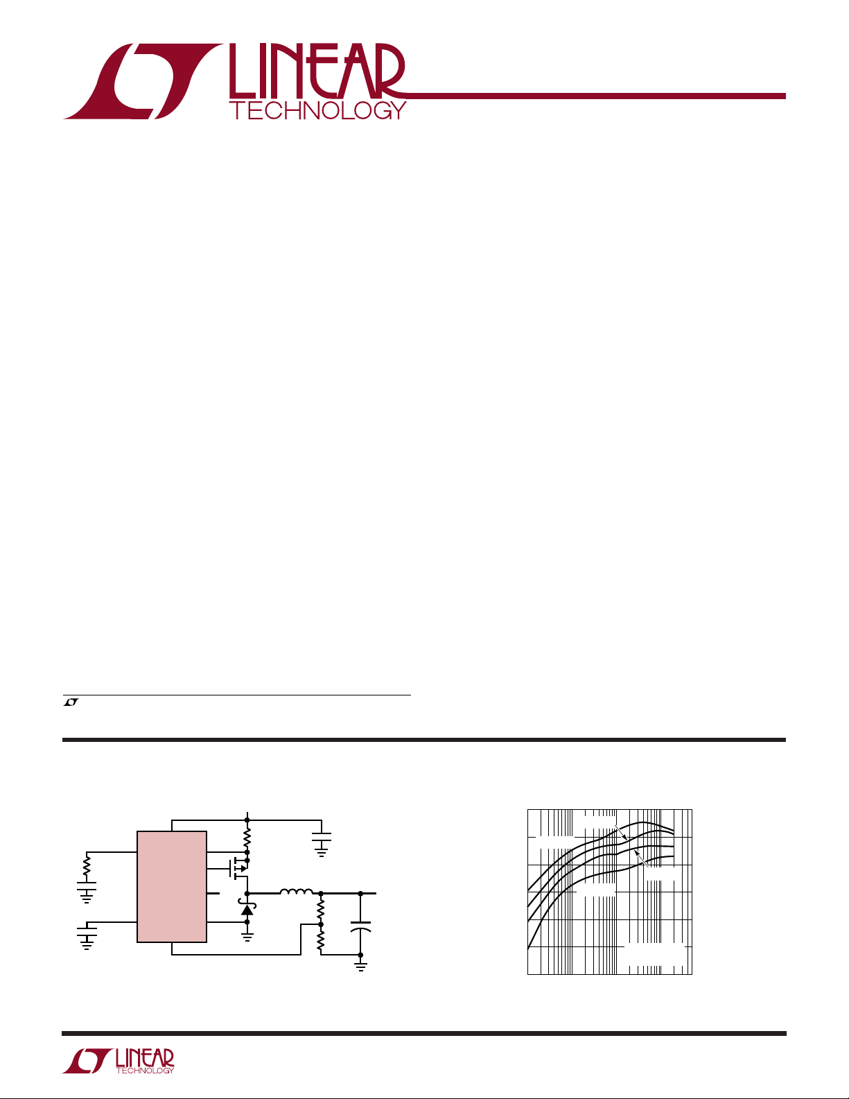
Figure 1. High Efficiency Step-Down Converter
R2
0.03Ω
Si3443DV
L1: MURATA LQN6C-4R7
R2: DALE WSL-1206 0-03Ω
U
4.7µH
D1
IR10BQ015
Efficiency vs Load Current with
Burst Mode Operation Enabled
100
C1
10µF
10V
L1
R3
159k
R4
75k
V
OUT
2.5V
1.5A
+
C2
47µF
6V
1622 F01a
90
80
70
EFFICIENCY (%)
60
50
40
1 100 1000 5000
VIN = 3.3V
10
VIN = 4.2V
VIN = 8.4V
V
OUT
R
SENSE
LOAD CURRENT (mA)
VIN = 6V
= 2.5V
= 0.03Ω
1622 F01b
1
Page 2
LTC1622
WW
W
ABSOLUTE MAXIMUM RATINGS
U
(Note 1)
Input Supply Voltage (VIN).........................–0.3V to 10V
RUN/SS Voltage .......................................–0.3V to 2.4V
SYNC/MODE Voltage ................................. –0.3V to V
SENSE– Voltage .......................................... 2.4V to V
IN
IN
PDRV Peak Output Current (<10µs) ......................... 1A
Storage Ambient Temperature Range ... –65°C to 150°C
U
W
U
PACKAGE/ORDER INFORMATION
ORDER PART
NUMBER
LTC1622CMS8
MS8 PART MARKING
LTDB
–
SENSE
1
2
I
TH
3
V
FB
4
RUN/SS
MS8 PACKAGE
8-LEAD PLASTIC MSOP
T
= 125°C, θJA = 250°C/W
JMAX
TOP VIEW
8
V
IN
7
PDRV
6
GND
5
SYNC/MODE
Operating Temperature Range
Commercial ............................................ 0°C to 70°C
Industrial ........................................... –45°C to 85°C
Junction Temperature (Note 2)............................. 125°C
Lead Temperature (Soldering, 10 sec).................. 300°C
ORDER PART
SENSE
I
V
RUN/SS
TOP VIEW
–
1
2
TH
3
FB
4
S8 PACKAGE
8-LEAD PLASTIC SO
T
= 125°C, θJA = 150°C/ W
JMAX
V
8
IN
PDRV
7
GND
6
SYNC/MODE
5
NUMBER
LTC1622CS8
LTC1622IS8
S8 PART MARKING
1622
1622I
Consult factory for Military grade parts.
ELECTRICAL CHARACTERISTICS
The ● denotes specifications which apply over the full operating
temperature range, otherwise specifications are at TA = 25°C. VIN = 4.2V
SYMBOL PARAMETER CONDITIONS MIN TYP MAX UNITS
I
VFB
V
FB
V
OVL
∆V
OSENSE
V
LOADREG
I
S
V
RUN/SS
I
RUN/SS
f
OSC
V
SYNC/MODE
V
UVLO
Feedback Current (Note 3) VFB = 0.8V 10 70 nA
Regulated Feedback Voltage (Note 3) Commercial Grade ● 0.785 0.8 0.815 V
(Note 3) Industrial Grade
Output Overvoltage Lockout Referenced to Nominal V
Reference Voltage Line Regulation VIN = 4.2V to 8.5V (Note 3) 0.04 0.08 %/V
Output Voltage Load Regulation Measured in Servo Loop; V
Measured in Servo Loop; V
Input DC Supply Current (Note 4)
Burst Mode Inhibited V
Sleep Mode V
Shutdown V
Shutdown V
RUN/SS Threshold Commercial Grade ● 0.4 0.7 0.9 V
Soft-Start Current Source V
Oscillator Frequency VFB = 0.8V 475 550 625 kHz
SYNC/MODE Threshold V
Undervoltage Lockout VIN Ramping Down ● 1.55 1.92 2.3 V
= 2.3V 450 µA
IN
= 0V, V
ITH
RUN/SS
RUN/SS
Industrial Grade
RUN/SS
V
FB
SYNC/MODE
Ramping Up 1.97 2.36 V
V
IN
SYNC/MODE
= 0V 15 30 µA
= 0V, VIN = V
= 0V 1 2.5 5 µA
= 0V 75 110 140 kHz
Ramping Down 1 1.5 V
OUT
= 0.2V to 0.625V 0.3 0.5 %
ITH
= 0.9V to 0.625V – 0.3 –0.5 %
ITH
= 2.4V 350 400 µA
– 0.1V 4 10 µA
UVLO
● 0.780 0.8 0.820 V
4 7.5 10.5 %
● 0.3 0.7 1.0 V
2
Page 3

LTC1622
ELECTRICAL CHARACTERISTICS
The ● denotes specifications which apply over the full operating
temperature range, otherwise specifications are at TA = 25°C. VIN = 4.2V
SYMBOL PARAMETER CONDITIONS MIN TYP MAX UNITS
PDRV t
r
PDRV t
f
∆V
SENSE(MAX)
Note 1: Absolute Maximum Ratings are those values beyond which the life
of a device may be impaired.
Note 2: T
dissipation P
Gate Drive Rise Time C
Gate Drive Fall Time C
= 3000pF 80 140 ns
LOAD
= 3000pF 100 140 ns
LOAD
Maximum Current Sense Voltage ● 80 110 140 mV
Note 3: The LTC1622 is tested in a feedback loop that servos V
= 0.8V).
ITH
is calculated from the ambient temperature TA and power
J
according to the following formula:
D
feedback point for the error amplifier (V
Note 4: Dynamic supply current is higher due to the gate charge being
delivered at the switching frequency.
to the
FB
LTC1622CS8; TJ = TA + (PD • 150°C/W),
LTC1622CMS8; TJ = TA + (PD • 250°C/W)
W
U
TYPICAL PERFORMANCE CHARACTERISTICS
Shutdown Current
vs Supply Voltage
45
40
35
30
25
20
15
SHUTDOWN CURRENT (µA)
10
5
0
23
45
67
SUPPLY VOLTAGE (V)
89
1622 G01
RUN/SS Current vs Supply Voltage
3.50
3.00
2.50
2.00
SOFT-START CURRENT (µA)
1.50
10
1.00
3579
2
46 10
SUPPLY VOLTAGE (V)
8
1622 G02
Maximum Current Sense Voltage
vs Duty Cycle
110
VIN = 4.2V
100
90
80
70
60
TRIP VOLTAGE (mV)
50
40
30
20 30
40 50
DUTY CYCLE (%)
UNSYNC
60 70
80 90
100
1622 G03
Normalized Oscillator Frequency
vs Temperature
10.0
VIN = 4.2V
7.5
5.0
2.5
0
–2.5
–5.0
NORMALIZED FREQUENCY (%)
–7.5
–10.0
–55 –35
–15 5
25 45 65
TEMPERATURE (°C)
85 105
1622 G04
125
Reference Voltage
vs Temperature
0.810
VIN = 4.2V
0.805
0.800
0.795
0.790
0.785
REFERENCE VOLTAGE (V)
0.780
0.775
–55 –35
–15 5
TEMPERATURE (°C)
25 45 65
85 105
1622 G05
125
Undervoltage Lockout Voltage
vs Temperature
2.10
2.05
2.00
1.95
1.90
1.85
1.80
UNDERVOLTAGE LOCKOUT VOLTAGE (V)
1.75
–55 –35
–15 5
25 45 65
TEMPERATURE (°C)
85 105
125
1622 G06
3
Page 4
LTC1622
W
U
TYPICAL PERFORMANCE CHARACTERISTICS
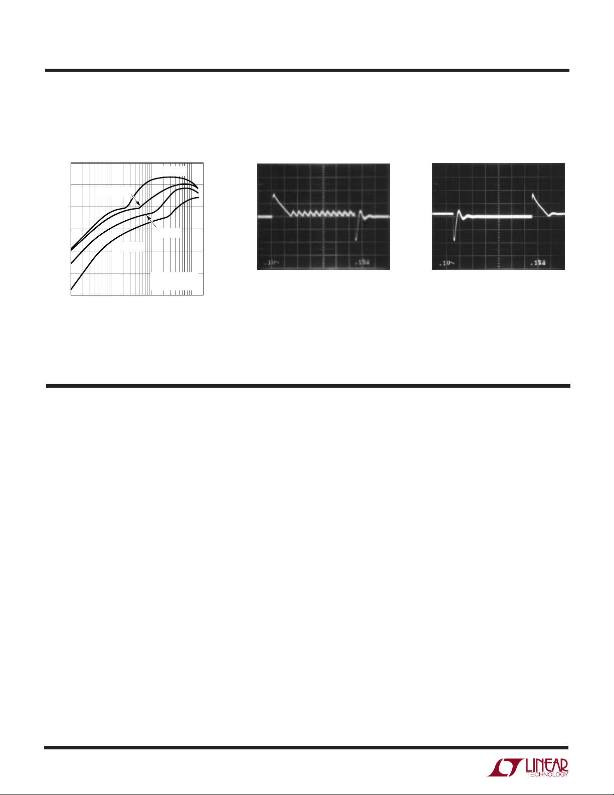
Efficiency vs Load Current for
Figure 1 with Burst Mode
Operation Defeated
100
90
80
VIN = 4.2V
VIN = 3.3V
Load Step Transient Response
Burst Enabled
Load Step Transient Response
Burst Inhibited
70
EFFICIENCY (%)
60
50
40
1
VIN = 6V
VIN = 8.4V
V
OUT
R
SENSE
10 100
LOAD CURRENT (mA)
= 2.5V
= 0.03Ω
1000
1622 G07
100mV/DIV
I
= 50mA TO 1.2A
LOAD
VIN = 4.2V
UUU
PIN FUNCTIONS
SENSE– (Pin 1): The Negative Input to the Current Comparator.
ITH (Pin 2): Error Amplifier Compensation Point. The
current comparator threshold increases with this control
voltage. Nominal voltage range for this pin is 0V to 1.2V.
VFB (Pin 3): Receives the feedback voltage from an external resistive divider across the output capacitor.
100mV/DIV
I
= 50mA TO 1.2A
LOAD
1622 G08
VIN = 4.2V
1622 G09
SYNC/MODE (Pin 5): This pin performs three functions.
Greater than 2V on this pin allows Burst Mode operation
at low load currents, while grounding or applying a clock
signal on this pin defeats Burst Mode operation. An
external clock between 625kHz and 750kHz applied to this
pin forces the LTC1622 to operate at the external clock
frequency.
Do not attempt to synchronize below 625kHz
.
Pin 5 has an internal 1µA pull-up current source.
RUN/SS (Pin 4): Combination of Soft-Start and Run
Control Inputs. A capacitor to ground at this pin sets the
ramp time to full output current. The time is approximately
0.45s/µF. Forcing this pin below 0.4V causes all circuitry
to be shut down.
4
GND (Pin 6): Ground Pin.
PDRV (PIN 7): Gate Drive for the External P-Channel
MOSFET. This pin swings from 0V to VIN.
VIN (Pin 8): Main Supply Pin. Must be closely decoupled
to ground Pin 6.
Page 5
LTC1622
UU
W
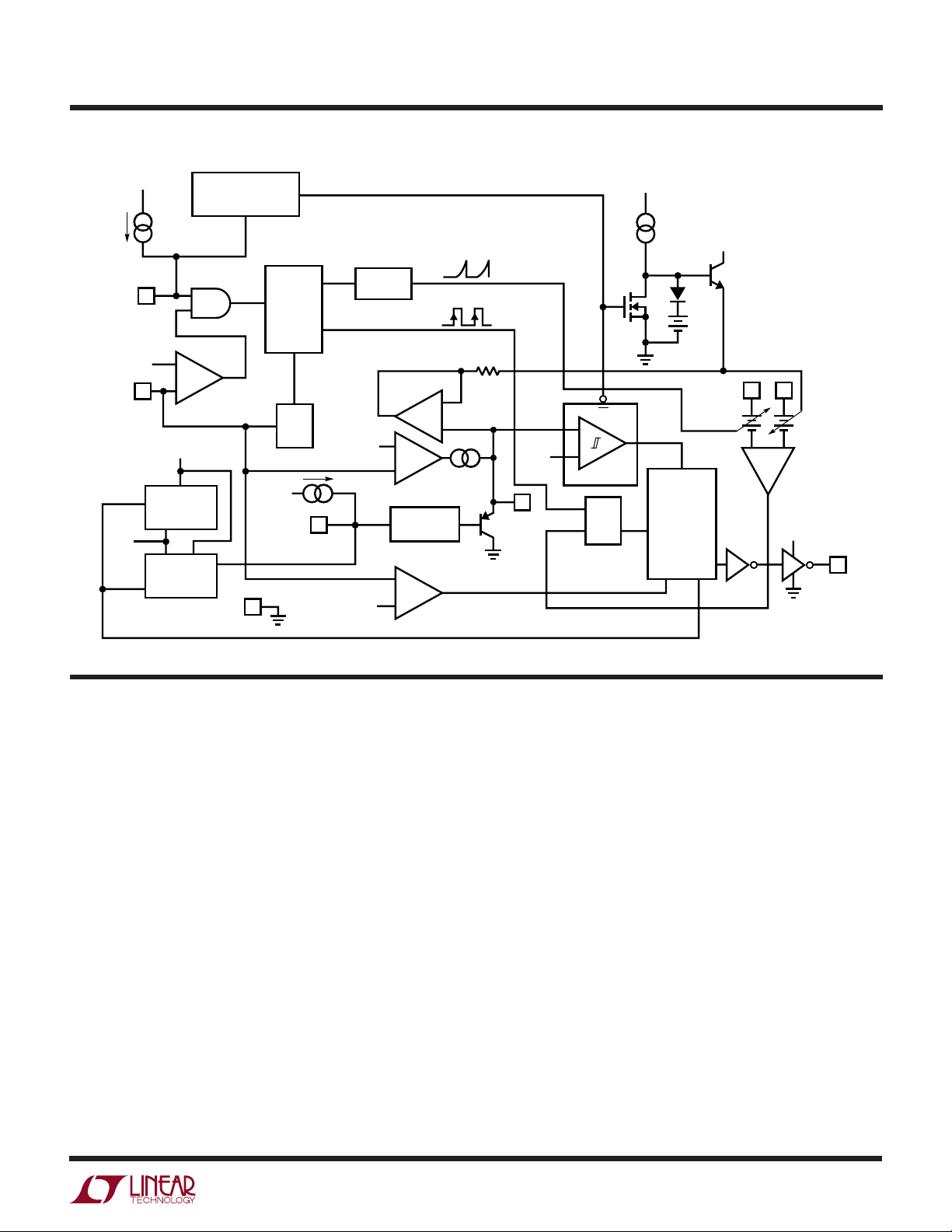
FUNCTIONAL DIAGRA
V
SYNC/
MODE
V
FB
V
REF
0.8V
IN
1µA
5
0.3V
3
REFERENCE
TRIP = 1.97V
SHUTDOWN
–
+
V
IN
0.8V
UVLO
BURST DEFEAT
X
6
GND
Y
OSC
FREQ
SHIFT
V
IN
RUN/SS
4
V
REF
Y = “0” ONLY WHEN X IS A CONSTANT “1”
OTHERWISE Y = “1”
SLOPE
COMP
–
0.8V
V
2.5µA
+ 60mV
REF
+
+
EA
–
g
= 0.5m
m
RUN/
SOFT-START
+
OV
–
Ω
2
I
TH
0.12V
EN
–
+
BURST
S
RQ
R
S1
V
CC
SLEEP
SWITCHING
BLANKING
LOGIC
AND
CIRCUIT
0.36V
SENSE
1622 BD
–
1
+
ICOMP
V
8
IN
–
V
IN
PDRV
7
U
OPERATIO
Main Control Loop
The LTC1622 is a constant frequency current mode switching regulator. During normal operation, the external
P-channel power MOSFET is turned on each cycle when
the oscillator sets the RS latch (RS1) and turned off when
the current comparator (I
inductor current at which I
controlled by the voltage on the ITH pin, which is the output
of the error amplifier EA. An external resistive divider
connected between V
an output feedback voltage VFB. When the load current
increases, it causes a slight decrease in VFB relative to the
0.8V reference, which in turn causes the ITH voltage to
increase until the average inductor current matches the
new load current.
The main control loop is shut down by pulling the RUN/SS
pin low. Releasing RUN/SS allows an internal 2.5µA
(Refer to Functional Diagram)
) resets the latch. The peak
COMP
resets the RS latch is
COMP
and ground allows EA to receive
OUT
current source to charge up the soft-start capacitor CSS.
When CSS reaches 0.7V, the main control loop is enabled
with the ITH voltage clamped at approximately 5% of its
maximum value. As CSS continues to charge, ITH is gradually released allowing normal operation to resume.
Comparator OV guards against transient overshoots
>7.5% by turning off the P-channel power MOSFET and
keeping it off until the fault is removed.
Burst Mode Operation
The LTC1622 can be enabled to go into Burst Mode
operation at low load currents simply by leaving the SYNC/
MODE pin open or connecting it to a voltage of at least 2V.
In this mode, the peak current of the inductor is set as if
V
= 0.36V (at low duty cycles) even though the voltage
ITH
at the ITH pin is at lower value. If the inductor’s average
current is greater than the load requirement, the voltage at
5
Page 6

LTC1622
OPERATIO
U
(Refer to Functional Diagram)
the ITH pin will drop. When the ITH voltage goes below
0.12V, the sleep signal goes high, turning off the external
MOSFET. The sleep signal goes low when the ITH voltage
rises above 0.22V and the LTC1622 resumes normal
operation. The next oscillator cycle will turn the external
MOSFET on and the switching cycle repeats.
Frequency Synchronization
The LTC1622 can be externally driven by a TTL/CMOS
compatible clock signal up to 750kHz.
Do not
synchronize
the LTC1622 below its maximum default operating frequency of 625kHz as this may cause abnormal operation
and an undesired frequency spectrum. The LTC1622 is
synchronized to the rising edge of the clock. The external
clock pulse width must be at least 100ns and not more
than the period minus 200ns.
Synchronization is inhibited when the feedback voltage is
below 0.3V. This is to prevent inductor current buildup
under short-circuit conditions. Burst Mode operation is
deactivated when the LTC1622 is externally driven by a
clock.
Dropout Operation
Short-Circuit Protection
When the output is shorted to ground, the frequency of the
oscillator will be reduced to about 110kHz. This lower
frequency allows the inductor current to safely discharge,
thereby preventing current runaway. The oscillator’s frequency will gradually increase to its nominal value when
the feedback voltage increases above 0.65V. Note that
synchronization is inhibited until the feedback voltage
goes above 0.3V.
Overvoltage Protection
As a further protection, the overvoltage comparator in the
LTC1622 will turn the external MOSFET off when the
feedback voltage has risen 7.5% above the reference
voltage of 0.8V. This comparator has a typical hysteresis
of 35mV.
Slope Compensation and Peak Inductor Current
The inductor’s peak current is determined by:
V
I
PK
=
ITH
R
10
SENSE
()
When the input supply voltage decreases towards the
output voltage, the rate of change of inductor current
during the ON cycle decreases. This reduction means that
the P-channel MOSFET will remain on for more than one
oscillator cycle since the inductor current has not ramped
up to the threshold set by EA. Further reduction in input
supply voltage will eventually cause the P-channel MOSFET
to be turned on 100%, i.e., DC. The output voltage will then
be determined by the input voltage minus the voltage drop
across the MOSFET, the sense resistor and the inductor.
Undervoltage Lockout
To prevent operation of the P-channel MOSFET below safe
input voltage levels, an undervoltage lockout is incorporated into the LTC1622. When the input supply voltage
drops below 2V, the P-channel MOSFET and all circuitry is
turned off except the undervoltage block, which draws
only several microamperes.
when the LTC1622 is operating below 40% duty cycle.
However, once the duty cycle exceeds 40%, slope compensation begins and effectively reduces the peak inductor current. The amount of reduction is given by the curves
in Figure 2.
110
100
90
80
(%)
70
60
OUT(MAX)
/I
OUT
SF = I
Figure 2. Maximum Output Current vs Duty Cycle
I
= 0.4I
50
40
30
20
10
RIPPLE
AT 5% DUTY CYCLE
I
= 0.2I
RIPPLE
AT 5% DUTY CYCLE
VIN = 4.2V
UNSYNC
0 70 80 90 1006010 20 30 40 50
DUTY CYCLE (%)
PK
PK
1622 F02
6
Page 7

LTC1622
U
WUU
APPLICATIONS INFORMATION
The basic LTC1622 application circuit is shown in Figure
1. External component selection is driven by the load
requirement and begins with the selection of L and R
Next, the Power MOSFET and the output diode D1 are
selected followed by CIN and C
R
R
Selection for Output Current
SENSE
is chosen based on the required output current.
SENSE
OUT
.
With the current comparator monitoring the voltage developed across R
, the threshold of the comparator
SENSE
determines the inductor’s peak current. The output current the LTC1622 can provide is given by:
I
OUT
where I
0082.
=−
R
SENSE
is the inductor peak-to-peak ripple current
RIPPLE
I
RIPPLE
(see Inductor Value Calculation section).
A reasonable starting point for setting ripple current is
I
RIPPLE
= (0.4)(I
). Rearranging the above equation, it
OUT
becomes:
SENSE
.
V
. The inductor’s peak-to-peak ripple current is given
OUT
by:
I
RIPPLE
VVfLVV
−
IN OUT OUT D
=
()
VV
IN D
+
+
where f is the operating frequency. Accepting larger values
of I
allows the use of low inductances, but results in
RIPPLE
higher output voltage ripple and greater core losses. A
reasonable starting point for setting ripple current is
I
RIPPLE
= 0.4(I
OUT(MAX)
). Remember, the maximum I
RIPPLE
occurs at the maximum input voltage.
With Burst Mode operation selected on the LTC1622, the
ripple current is normally set such that the inductor
current is continuous during the burst periods. Therefore,
the peak-to-peak ripple current should not exceed:
I
RIPPLE
≤
0 036.
R
SENSE
This implies a minimum inductance of:
R
SENSE
=
1
for Duty Cycle < 40%
I
15
OUT
()( )
However, for operation that is above 40% duty cycle, slope
compensation has to be taken into consideration to select
the appropriate value to provide the required amount of
current. Using Figure 2, the value of R
R
SENSE
=
SF
15
I
OUT
100
()( )( )
SENSE
is:
Inductor Value Calculation
The operating frequency and inductor selection are interrelated in that higher operating frequencies permit the use
of a smaller inductor for the same amount of inductor
ripple current. However, this is at the expense of efficiency
due to an increase in MOSFET gate charge losses.
The inductance value also has a direct effect on ripple
current. The ripple current, I
, decreases with higher
RIPPLE
inductance or frequency and increases with higher VIN or
VV
−
L
MIN
(Use V
IN OUT
=
f
R
IN(MAX)
0 036.
SENSE
= VIN)
A smaller value than L
VV
OUT D
VV
IN D
could be used in the circuit;
MIN
+
+
however, the inductor current will not be continuous
during burst periods.
Inductor Core Selection
Once the value for L is known, the type of inductor must be
selected. High efficiency converters generally cannot
afford the core loss found in low cost powdered iron cores,
forcing the use of more expensive ferrite, molypermalloy
or Kool Mu® cores. Actual core loss is independent of core
size for a fixed inductor value, but it is very dependent on
inductance selected. As inductance increases, core losses
go down. Unfortunately, increased inductance requires
more turns of wire and therefore copper losses will
increase. Ferrite designs have very low core losses and are
Kool Mu is a registered trademark of Magnetics, Inc.
7
Page 8

LTC1622
I
VV
VV
I
D
IN OUT
IN D
OUT
=
−
+
U
WUU
APPLICATIONS INFORMATION
preferred at high switching frequencies, so design goals
can concentrate on copper loss and preventing saturation.
Ferrite core materials saturate “hard,” which means that
the inductance collapses abruptly when the peak design
current is exceeded. This results in an abrupt increase in
inductor ripple current and consequently, output voltage
ripple. Do not allow the core to saturate!
Molypermalloy (from Magnetics, Inc.) is a very good, low
loss core material for toroids, but it is more expensive than
ferrite. A reasonable compromise from the same manufacturer is Kool Mu. Toroids are very space efficient,
especially when you can use several layers of wire.
Because they generally lack a bobbin, mounting is more
difficult. However, new surface mountable designs that do
not increase the height significantly are available.
Power MOSFET Selection
An external P-channel power MOSFET must be selected
for use with the LTC1622. The main selection criteria for
the power MOSFET are the threshold voltage V
the “on” resistance R
C
and total gate charge.
RSS
Since the LTC1622 is designed for operation down to low
input voltages, a sublogic level threshold MOSFET (R
guaranteed at VGS = 2.5V) is required for applications that
work close to this voltage. When these MOSFETs are used,
make sure that the input supply to the LTC1622 is less than
the absolute maximum MOSFET VGS rating, typically 8V.
The gate drive voltage levels are from ground to VIN.
The required minimum R
erned by its allowable power dissipation. For applications
that may operate the LTC1622 in dropout, i.e., 100% duty
cycle, at its worst case the required R
R
DS ON
()
DC
where PP is the allowable power dissipation and δp is the
temperature dependency of R
given for a MOSFET in the form of a normalized R
temperature curve, but δp = 0.005/°C can be used as an
approximation for low voltage MOSFETs.
100
=
%=
,reverse transfer capacitance
DS(ON)
of the MOSFET is gov-
DS(ON)
is given by:
DS(ON)
P
P
2
+
Ip
()
OUT MAX
()
1 δ
()
. (1 + δp) is generally
DS(ON)
GS(TH)
DS(ON)
DS(ON)
and
vs
In applications where the maximum duty cycle is less than
100% and the LTC1622 is in continuous mode, the R
is governed by:
P
R
DS ON
where DC is the maximum operating duty cycle of the
LTC1622.
When the LTC1622 is operating in continuous mode, the
MOSFET power dissipation is:
P
MOSFET
where K is a constant inversely related to gate drive
current. Because of the high switching frequency, the
second term relating to switching loss is important not to
overlook. The constant K = 3 can be used to estimate the
contributions of the two terms in the MOSFET dissipation
equation.
Output Diode Selection
The catch diode carries load current during the off-time.
The average diode current is therefore dependent on the
P-channel switch duty cycle. At high input voltages the
diode conducts most of the time. As VIN approaches V
the diode conducts only a small fraction of the time. The
most stressful condition for the diode is when the output
is short circuited. Under this condition the diode must
safely handle I
it is important to adequately specify the diode peak current
and average power dissipation so as not to exceed the
diode ratings.
Under normal load conditions, the average current conducted by the diode is:
≅
()
=
+
DC I
()
VV
VV
KV I C f
()( )( )()
PEAK
P
2
+
1 δ
p
()
OUT
+
OUT D
+
IN D
2
IN OUT RSS
at close to 100% duty cycle. Therefore,
2
IpR
OUT DS ON
()
+
1 δ
()
DS(ON)
()
OUT
8
Page 9

LTC1622
U
WUU
APPLICATIONS INFORMATION
The allowable forward voltage drop in the diode is calculated from the maximum short-circuit current as:
P
V
≈
F
where PD is the allowable power dissipation and will be
determined by efficiency and/or thermal requirements.
A fast switching diode must also be used to optimize
efficiency. Schottky diodes are a good choice for low
forward drop and fast switching times. Remember to keep
lead length short and observe proper grounding (see
Board Layout Checklist) to avoid ringing and increased
dissipation.
CIN and C
In continuous mode, the source current of the P-channel
MOSFET is a square wave of duty cycle (V
(VIN + VD). To prevent large voltage transients, a low ESR
input capacitor sized for the maximum RMS current must
be used. The maximum RMS capacitor current is given by:
CI
IN MAX
This formula has a maximum at VIN = 2V
= I
OUT
used for design because even significant deviations do not
offer much relief. Note that capacitor manufacturer’s
ripple current ratings are often based on 2000 hours of life.
This makes it advisable to further derate the capacitor, or
to choose a capacitor rated at a higher temperature than
required. Several capacitors may be paralleled to meet the
size or height requirements in the design. Due to the high
operating frequency of the LTC1622, ceramic capacitors
can also be used for CIN. Always consult the manufacturer
if there is any question.
The selection of C
series resistance (ESR). Typically, once the ESR requirement is satisfied, the capacitance is adequate for filtering.
The output ripple (∆V
D
I
SC MAX
()
Selection
OUT
+ VD)/
OUT
12/
VVV
OUT IN OUT
Required I
/2. This simple worst-case condition is commonly
≈
RMS
is driven by the required effective
OUT
OUT
[]
) is approximated by:
−
()
V
IN
, where I
OUT
RMS
∆V I ESR
where f is the operating frequency, C
capacitance and I
tor. The output ripple is highest at maximum input voltage
since ∆IL increases with input voltage.
The choice of using a smaller output capacitance increases the output ripple voltage due to the frequency
dependent term, but can be compensated for by using
capacitors of very low ESR to maintain low ripple voltage.
The ITH pin OPTI-LOOP compensation components can be
optimized to provide stable, high performance transient
response regardless of the output capacitors selected.
Manufacturers such as Nichicon, United Chemicon and
Sanyo should be considered for high performance throughhole capacitors. The OS-CON semiconductor dielectric
capacitor available from Sanyo has the lowest ESR (size)
product of any aluminum electrolytic at a somewhat
higher price. Once the ESR requirement for C
met, the RMS current rating generally far exceeds the
I
RIPPLE(P-P)
In surface mount applications, multiple capacitors may
have to be paralleled to meet the ESR or RMS current
handling requirements of the application. Aluminum electrolytic and dry tantalum capacitors are both available in
surface mount configurations. In the case of tantalum, it is
critical that the capacitors are surge tested for use in
switching power supplies. An excellent choice is the AVX
TPS, AVX TPSV and KEMET T510 series of surface mount
tantalum, available in case heights ranging from 2mm to
4mm. Other capacitor types include Sanyo OS-CON, Sanyo
POSCAP, Nichicon PL series and the Panasonic SP series.
Low Supply Operation
Although the LTC1622 can function down to 2V, the
maximum allowable output current is reduced when V
decreases below 3V. Figure 3 shows the amount of change
as the supply is reduced down to 2V. Also shown in
Figure 3 is the effect of VIN on V
Remember the maximum voltage on the ITH pin defines
≈+
OUT RIPPLE
requirement.
RIPPLE
8
is the ripple current in the induc-
1
fC
OUT
is the output
OUT
has been
OUT
as VIN goes below 2.3V.
REF
IN
9
Page 10

LTC1622
U
WUU
APPLICATIONS INFORMATION
101
V
100
99
98
97
NORMALIZED VOLTAGE (%)
96
95
2.0
Figure 3. Line Regulation of V
the maximum current sense voltage that sets the maximum output current.
Setting Output Voltage
The LTC1622 develops a 0.8V reference voltage between
the feedback (Pin 3) terminal and ground (see Figure 4). By
selecting resistor R1, a constant current is caused to flow
through R1 and R2 to set the output voltage. The regulated
output voltage is determined by:
REF
V
ITH
2.2 2.4 2.6 2.8
INPUT VOLTAGE (V)
REF
3.0
1622 F03
and V
ITH
is limiting the efficiency and which change would produce
the most improvement. Efficiency can be expressed as:
Efficiency = 100% – (η1 + η2 + η3 + ...)
where η1, η2, etc. are the individual losses as a percentage of input power.
Although all dissipative elements in the circuit produce
losses, four main sources usually account for most of the
losses in LTC1622 circuits: 1) LTC1622 DC bias current,
2) MOSFET gate charge current, 3) I2R losses, 4) voltage
drop of the output diode and 5) transition losses.
1. The VIN current is the DC supply current, given in the
electrical characteristics, that excludes MOSFET driver
and control currents. VIN current results in a small loss
which increases with VIN.
2. MOSFET gate charge current results from switching
the gate capacitance of the power MOSFET. Each time
a MOSFET gate is switched from low to high to low
again, a packet of charge dQ moves from VIN to ground.
The resulting dQ/dt is a current out of VIN which is
typically much larger than the DC supply current. In
continuous mode, I
GATECHG
= f(Qp).
V
=+
08 1
OUT
.
R
2
R
1
For most applications, a 30k resistor is suggested for R1.
To prevent stray pickup, an optional 100pF capacitor is
suggested across R1 located close to LTC1622.
V
OUT
100pF
R2
R1
1622 F04
LTC1622
Figure 4. Setting Output Voltage
3
V
FB
Efficiency Considerations
The efficiency of a switching regulator is equal to the
output power divided by the input power times 100%. It is
often useful to analyze individual losses to determine what
3. I2R losses are predicted from the DC resistances of the
MOSFET, inductor and current shunt. In continuous
mode the average output current flows through L but
is “chopped” between the P-channel MOSFET in series
with R
plus R
and the output diode. The MOSFET R
SENSE
multiplied by duty cycle can be summed
SENSE
DS(ON)
with the resistance of the inductor to obtain I2R losses.
4. The output diode is a major source of power loss at
high currents and gets worse at high input voltages.
The diode loss is calculated by multiplying the forward
voltage drop times the diode duty cycle multiplied by
the load current. For example, assuming a duty cycle of
50% with a Schottky diode forward voltage drop of
0.4V, the loss increases from 0.5% to 8% as the load
current increases from 0.5A to 2A.
5. Transition losses apply to the external MOSFET and
increase with higher operating frequencies and input
voltages. Transition losses can be estimated from:
10
Page 11

LTC1622
U
WUU
APPLICATIONS INFORMATION
Transition Loss = 3(VIN)2I
O(MAX)CRSS
Other losses including CIN and C
losses, and inductor core losses, generally account for
less than 2% total additional loss.
Run/Soft-Start Function
The RUN/SS pin is a dual purpose pin that provides the
soft-start function and a means to shut down the LTC1622.
Soft-start reduces input surge current from VIN by gradually increasing the internal current limit. Power supply
sequencing can also be accomplished using this pin.
An internal 2.5µA current source charges up an external
capacitor CSS. When the voltage on the RUN/SS reaches
0.7V the LTC1622 begins operating. As the voltage on
RUN/SS continues to ramp from 0.7V to 1.8V, the internal
current limit is also ramped at a proportional linear rate.
The current limit begins near 0A (at V
ends at 0.1/R
SENSE
(V
≥ 1.8V). The output current
RUN/SS
thus ramps up slowly, reducing the starting surge current
required from the input power supply. If the RUN/SS has
been pulled all the way to ground, there will be a delay
before the current limit starts increasing and is given by:
(f)
ESR dissipative
OUT
= 0.7V) and
RUN/SS
V
D
FB
1622 F05
OUT
LTC1622
V
I
TH
Figure 5. Foldback Current Limiting
R2
FB
+
R1
Design Example
Assume the LTC1622 is used in a single lithium-ion
battery-powered cellular phone application. The VIN will be
operating from a maximum of 4.2V down to a minimum of
2.7V. Load current requirement is a maximum of 1.5A but
most of the time it will be on standby mode, requiring only
2mA. Efficiency at both low and high load current is
important. Output voltage is 2.5V.
In the above application, Burst Mode operation is enabled
by connecting Pin 5 to VIN.
VV
+
Maximum
Duty Cycle =
OUT D
VV
IN MIN D
+
()
%93
=
t
= 2.8 • 105 • CSS in seconds
DELAY
Pulling the RUN/SS pin below 0.4V puts the LTC1622 into
a low quiescent current shutdown (IQ < 15µA).
Foldback Current Limiting
As described in the Output Diode Selection, the worstcase dissipation occurs with a short-circuited output
when the diode conducts the current limit value almost
continuously. To prevent excessive heating in the diode,
foldback current limiting can be added to reduce the
current in proportion to the severity of the fault.
Foldback current limiting is implemented by adding diode
DFB (1N4148 or equivalent) between the output and the I
pin as shown in Figure 5. In a hard short (V
= 0V), the
OUT
TH
current will be reduced to approximately 50% of the
maximum output current.
From Figure 2, SF = 57%.
Use the curve of Figure 2 since the operating frequency is
the free running frequency of the LTC1622.
R
SENSE
=
SF
15 100
I
()( )( )=()( )
OUT
057
.
15 1 5
.
A
=
0 0253
. Ω
In the application, a 0.025Ω resistor is used. For the
inductor, the required value is:
L
MIN
=
42 25
kHz
550
..
−
0 036
.
0 025
.
25 03
..
42 03
..
+
+
=
133
.µ
H
In the application, a 3.9µH inductor is used to reduce
inductor ripple current and thus, output voltage ripple.
For the selection of the external MOSFET, the R
DS(ON)
must be guaranteed at 2.5V since the LTC1622 has to work
11
Page 12

LTC1622
U
WUU
APPLICATIONS INFORMATION
down to 2.7V. Let’s assume that the MOSFET dissipation
is to be limited to PP = 250mW and its thermal resistance
is 50°C/W. Hence the junction temperature at TA = 25°C
will be 37.5°C and δp = 0.005 (37.5 – 25) = 0.0625. The
required R
R
DS ON
()
The P-channel MOSFET requirement can be met by an
Si6433DQ.
The requirement for the Schottky diode is the most stringent when V
R
resistor, the short-circuit current through the
SENSE
Schottky is 0.1/0.025 = 4A. An MBRS340T3 Schottky
diode is chosen. With 4A flowing through, the diode is
rated with a forward voltage of 0.4V. Therefore, the worstcase power dissipated by the diode is 1.6W. The addition
of DFB (Figure 5) will reduce the diode dissipation to
approximately 0.8W.
The input capacitor requires an RMS current rating of at
least 0.75A at temperature, and C
of 0.1Ω for optimum efficiency.
PC Board Layout Checklist
When laying out the printed circuit board, the following
checklist should be used to ensure proper operation of the
LTC1622. These items are illustrated graphically in the
is then given by:
DS(ON)
P
P
DC I p
OUT
2
+
()
OUT
1
()
= 0V, i.e., short circuit. With a 0.025Ω
.≅
=
011δΩ
will require an ESR
OUT
layout diagram in Figure 6. Check the following in your
layout:
1. Is the Schottky diode closely connected between ground
at (–) lead of CIN and drain of the external MOSFET?
2. Does the (+) plate of CIN connect to the sense resistor
as closely as possible? This capacitor provides AC
current to the MOSFET.
3. Is the input decoupling capacitor (0.1µF) connected
closely between VIN (Pin 8) and ground (Pin 6)?
4. Connect the end of R
as close to VIN (Pin 8) as
SENSE
possible. The VIN pin is the SENSE+ of the current
comparator.
5. Is the trace from the SENSE– (Pin 1) to the Sense
resistor kept short? Does the trace connect close to
R
SENSE
?
6. Keep the switching node, SW, away from sensitive
small signal nodes.
7. Does the VFB pin connect directly to the feedback
resistors? The resistive divider R1 and R2 must be
connected between the (+) plate of C
and signal
OUT
ground. Optional capacitor C1 should be located as
close as possible to the LTC1622.
R1 and R2 should be located as close as possible to the
LTC1622. R2 should connect to the output as close to
the load as practicable.
12
+
R
SENSE
1
–
SENSE
2
I
TH
LTC1622
3
V
4
RUN/
SS
C
SS
FB
QUIET SGND
R
ITH
C
ITH
R1
BOLD LINES INDICATE HIGH CURRENT PATHS
C1
R2
Figure 6. LTC1622 Layout Diagram (See PC Board Layout Checklist)
V
PDRV
GND
SYNC/
MODE
8
IN
7
6
5
0.1µF
M1
SW
V
IN
C
IN
L1
+
1622 F06
V
OUT
C
OUT
Page 13

U
TYPICAL APPLICATIONS
LTC1622 1.8V/1.5A Regulator with Burst Mode Operation Disabled
LTC1622
V
IN
2.5V TO
8.5V
R1
10K
C3
220pF
C4
560pF
C1: AVX TPSD476M016R0150
C2: AVX TPSD227M006R0100
L1: MURATA LQN6C3R3
R1
10k
C1
1
2
3
4
SENSE
I
TH
V
FB
RUN/
SS
–
LTC1622
47µF
8
V
IN
7
PDRV
6
GND
5
SYNC/
MODE
R2: DALE WSL-1206 0.025Ω
U1: INTERNATIONAL RECTIFIER
16V
+
R2
0.025Ω
1
2
3
4
FETKY
U1
TM
IRF7422D2
8
7
6
5
LTC1622 2.5V/2A Regulator with Burst Mode Operation Enabled
+
C1
47µF
16V
× 2
C2
+
150µF
6V
× 2
C3
220pF
1
2
3
4
C4
560pF
SENSE
I
TH
V
FB
RUN/
SS
–
LTC1622
V
PDRV
GND
SYNC/
MODE
8
IN
7
D1
6
5
R2
0.02Ω
M1
L1
4.7µH
3.3µH
R3
158k
R4
75k
L1
R3
93.1k
R4
75k
V
IN
3.3V TO
8.5V
V
OUT
2.5V
2A
+
C2
220µF
6V
1622 TA01
V
OUT
1.8V
1.5A
C1: AVX TPSD476M016R0150
C2: SANYO POSCAP 6TPA47M
D1: MOTOROLA MBR320T3
L1: COILCRAFT D03316-472
M1: SILICONIX Si3443DV
R2: DALE WSL-2010 0.02Ω
FETKY
is a trademark of International Rectifier Corporation.
1622 TA02
13
Page 14

LTC1622
TYPICAL APPLICATIONS
LTC1622 2.5V/3A Regulator with External Frequency Synchronization
1
2
R1
10k
C3
220pF
3
4
C4
560pF
U
SENSE
I
TH
V
FB
RUN/
SS
–
LTC1622
V
PDRV
GND
SYNC/
MODE
V
IN
R3
158k
R4
75k
3.3V TO
8.5V
V
OUT
2.5V
3A
8
IN
7
6
5
650kHz
1.5V
P-P
R2
0.01Ω
M1
D1
L1
4.7µH
47µF
16V
× 2
C2
+
100µF
6.3V
× 2
C1
+
C1: AVX TPSD476M016R0150
C2: AVX TPSD107M010R0065
D1: MOTOROLA MBR320T3
Zeta Converter with Foldback Current Limit
D2
1N4818
R1
47k
C3
470pF
0.1µF
C1: AVX TPSD476M016R0150
C2: AVX TPSD107M010R0080
D1: MOTOROLA MBRS320T3
L1A, L1B: BH ELECTRONICS BH511-1012
R2: DALE WSL-1206 0.04Ω
1
–
SENSE
2
I
TH
LTC1622
3
V
FB
4
RUN/
SS
C4
V
PDRV
GND
SYNC/
MODE
IN
L1B
8
7
6
5
L1: COILCRAFT D03316-472
M1: SILICONIX Si3443DV
R2: DALE WSL-2512 0.01Ω
R2
0.04Ω
Si3441DV
47µF
L1A
6.2µH
3
TOP VIEW
4
16V
2
L1A
1
•
1622 TA03
V
IN
R3
232k
R4
75k
2.5V TO
8.5V
V
OUT
3.3V
1622 TA04
C1
+
47µF
16V
× 2
L1B
6.2µH
+
D1
+
C2
100µF
10V
VINI
OUT(MAX)
(V) (A)
2.5 0.45
3.3 0.70
5.0 0.95
6.0 1.00
8.4 1.05
14
Page 15

PACKAGE DESCRIPTION
U
Dimensions in inches (millimeters) unless otherwise noted.
MS8 Package
8-Lead Plastic MSOP
(LTC DWG # 05-08-1660)
0.118 ± 0.004*
(3.00 ± 0.102)
8
7
6
5
LTC1622
0.193 ± 0.006
(4.90 ± 0.15)
12
0.040
± 0.006
SEATING
PLANE
(1.02 ± 0.15)
0.012
(0.30)
0.0256
REF
(0.65)
BSC
0.007
(0.18)
0.021
± 0.006
(0.53 ± 0.015)
* DIMENSION DOES NOT INCLUDE MOLD FLASH, PROTRUSIONS OR GATE BURRS. MOLD FLASH,
PROTRUSIONS OR GATE BURRS SHALL NOT EXCEED 0.006" (0.152mm) PER SIDE
** DIMENSION DOES NOT INCLUDE INTERLEAD FLASH OR PROTRUSIONS.
INTERLEAD FLASH OR PROTRUSIONS SHALL NOT EXCEED 0.006" (0.152mm) PER SIDE
° – 6° TYP
0
0.118 ± 0.004**
4
3
0.034 ± 0.004
(0.86 ± 0.102)
(3.00 ± 0.102)
0.006 ± 0.004
(0.15 ± 0.102)
MSOP (MS8) 1098
S8 Package
8-Lead Plastic Small Outline (Narrow 0.150)
(LTC DWG # 05-08-1610)
0.189 – 0.197*
(4.801 – 5.004)
7
8
5
6
0.228 – 0.244
(5.791 – 6.197)
0.010 – 0.020
(0.254 – 0.508)
0.008 – 0.010
(0.203 – 0.254)
*
DIMENSION DOES NOT INCLUDE MOLD FLASH. MOLD FLASH
SHALL NOT EXCEED 0.006" (0.152mm) PER SIDE
**
DIMENSION DOES NOT INCLUDE INTERLEAD FLASH. INTERLEAD
FLASH SHALL NOT EXCEED 0.010" (0.254mm) PER SIDE
Information furnished by Linear Technology Corporation is believed to be accurate and reliable.
However, no responsibility is assumed for its use. Linear Technology Corporation makes no representation that the interconnection of its circuits as described herein will not infringe on existing patent rights.
× 45°
0°– 8° TYP
0.016 – 0.050
(0.406 – 1.270)
0.053 – 0.069
(1.346 – 1.752)
0.014 – 0.019
(0.355 – 0.483)
TYP
0.150 – 0.157**
(3.810 – 3.988)
1
3
2
4
0.004 – 0.010
(0.101 – 0.254)
0.050
(1.270)
BSC
SO8 1298
15
Page 16

LTC1622
LOAD CURRENT (mA)
1
EFFICIENCY (%)
100
90
80
70
60
50
10 100 1000
1622 TA05b
V
OUT
= 3.3V
R
SENSE
= 0.025Ω
VIN = 3.5V
VIN = 4.2V
VIN = 6V
TYPICAL APPLICATION
U
Small Footprint 3.3V/1A Regulator
1
–
SENSE
2
I
TH
3
V
R1
10k
C3
220pF
C1: MURATA CERAMIC GRM235Y5V106Z
C2: SANYO POSCAP 6TPA47M
D1: MOTOROLA MBRS120LT3
C3
470pF
R1
33k
C5
150pF
4
C4
560pF
RUN/
SS
1
2
3
4
C4
0.1µF
FB
SENSE
I
TH
V
RUN/
SS
LTC1622
LTC1622
FB
–
V
PDRV
GND
SYNC/
MODE
PDRV
SYNC/
MODE
GND
R2
8
IN
7
6
5
D1
L1: COILCRAFT D01608C-222
M1: SILICONIX Si3443DY
R2: DALE WSL-2010 0.025Ω
0.025Ω
M1
L1
2.2µH
47µF
C2
6V
Boost Converter 3.3V/2.5A
8
V
IN
7
6
5
+
Si6801DQ
C1
100µF
10V
+
+
C6
0.1µF
M1
C1
10µF
16V
CERAMIC
R3
232k
R4
75k
R2
0.015Ω
L1
4.6µH
D1
V
IN
3.3V TO
8.5V
V
OUT
3.3V
1A
1622 TA05
R3
105k
R4
20k
Efficiency vs Load Current
Efficiency vs Load Current With LTC1622
Configured as Boost Converter
100
V
= 5V
V
IN
3.3V
V
OUT
5V
2.5A
C2
+
220µF
10V
×2
OUT
R
SENSE
90
80
70
EFFICIENCY (%)
60
= 0.015Ω
VIN = 3.3V
C1, C2: SANYO POSCAP TPB SERIES
D1: MOTOROLA MBRD835L
L1: SUMIDA CEP123-4R6
M1: SILICONIX Si3442DV
R2: DALE WS-L2512 0.015Ω
1622 TA06a
50
0.001
0.01 0.1 1
LOAD CURRENT (mA)
1622 TA06b
RELATED PARTS
PART NUMBER DESCRIPTION COMMENTS
LTC1147 Series High Efficiency Step-Down Switching Regulator Controllers 100% DC, 3.5V ≤ VIN ≤ 16V, HV Version Has 20V
LT1375/LT1376 1.5A, 500kHz Step-Down Switching Regulators High Frequency, Small Inductor, High Efficiency
LTC1436/LTC1436-PLL High Efficiency, Low Noise, Synchronous Step-Down Converters 24-Pin Narrow SSOP, 3.5V ≤ VIN ≤ 36V
LTC1438/LTC1439 Dual, Low Noise, Synchronous Step-Down Converters Multiple Output Capability, 3.5V ≤ VIN ≤ 36V
LTC1474/LTC1475 Low Quiescent Current Step-Down DC/DC Converters Monolithic, MSOP, I
LTC1624 High Efficiency SO-8 N-Channel Switching Regulator Controller 8-Pin N-Channel Drive, 3.5V ≤ VIN ≤ 36V
LTC1626 Low Voltage, High Efficiency Step-Down DC/DC Converter Monolithic, Constant Off-Time, 2.5V ≤ VIN ≤ 6V
LTC1627/LTC1707 Low Voltage, Monolithic Synchronous Step-Down Regulator Low Supply Voltage Range: 2.65V to 8V, 0.5A
LTC1628 Dual High Efficiency 2-Phase Step-Down Controller Antiphase Drive, 3.5V ≤ VIN ≤ 36V, Protection
LTC1772 SOT-23 Current Mode Step-Down Controller 6-Lead SOT-23, 2.5V ≤ VIN ≤ 9.8V, 550kHz
LTC1735 High Efficiency, Low Noise Synchronous Switching Controller Burst Mode Operation, Protection, 3.5V ≤ VIN ≤ 36V
Linear T echnology Corporation
16
1630 McCarthy Blvd., Milpitas, CA 95035-7417
(408) 432-1900 ● FAX: (408) 434-0507
●
www.linear-tech.com
= 10µA
OUT
1622f LT/TP 0100 4K • PRINTED IN USA
LINEAR TECHNOLOGY CORPORATION 1998
IN
 Loading...