

Page 1
ELEC-XROMC COMI’ONEXTS GROUP
SW CORPORATION
f
DEVICE SPECIFICATION FOR
\
Light Emitting Diode
MODEL No.
LTlF67AF
1
1. These specification sheets include materials protected under the copyrjght of Sharp Corporation (“Sharp”).
Please do not reproduce or cause anyone to reproduce them without S* consent
2. When using this product, please 0bsen.e the absolute maximum ratin&!q.nd the instructions for use outlined
in these specification sheets, as well as the precautions mentioned bei@%. Sharp assumes no responsibility
for any damage resulting from use of the product which does not
and the instructions inchrded in these specification sheets, and the precautions mentioned below.
(Precautions)
(1) This products is designed for use in the foUowtig application areas;
* OA equipment * Audio visual equipment * Home tippliance
* Telecommunication equipment (Terminal)
* Tooling machines * Computers
[
If the use of the product in the above application areas is for equipment listed in paragraphs .
(2) or (3), please be sure to observe the precautions given ixi those respective paragraphs.
(2) Appropriate measures, such as fail-safe design and redundant design considering
the safec design of the overall system and equipment, should be taken to ensure reliability
and safety when this product is used for equipment which d&$nds high reliability and
safety in function and precision, such as ;
* Transportation control and safety equipment (aircraft, t@n, automobile etc.)
* Traffic signals * Gas leakage sensor breakers
* Other safety equipment
L
(3) Please do not use this product for equipment which require extremely high reliability
and safety in fnnction and precision, such as ;
* Space equipment * Tekcommunication equipment (for trunk lines)
+ Nuclear power control equipment
C
(4) Please contact and consult with a Sharp sales representative if there are any questions
regarding interpretation of the above three paragraphs.
* Medical equipment
* Measur@g.equipment
. . .
c&r+&
tith the absolute maximum ratings
Ii:. )
.
3
* R@ue and security equipment
/
I
I
1 .
3. Please contact and consult with a Sharp sales representative for any questions about this product.
CUSTOMER’S APPROVAL
DATE:
BY:
DATE:
PRESENTED BY:
Department General Manager of
Enginewing Dept.,BI
Opto-Electronic Devices Division
Electronic Components Group
SHARP CORPORATION
hp. & I t?b
:
Page 2
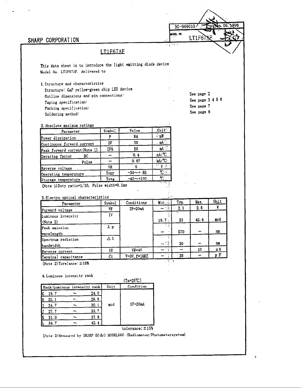
This data sheet is to introduce the light emitting diode device’
Model No. LTlF61.G. delivered
to
l.Structure and characteristics
Structure: CaP gellorgreen chip LED device
Outline dimensions and pin connections:
Taping specification:
Packing specification:
Soldering method:
@ate l.)Duty ratio=l/lO, Pulse width*. lm~
See page 2
See page 3
See page 7
See page 8
4 5 6
(Note 2)Tore!ance: 415%
4. Luminous intensity rank .
(Ta=25”C)
Condition
c 19.7 -
24. 0
H 22.1 - 26. 9
I 24.7 - 30. I mcd
J 27.7 -
K 31.0
L 34.7 -
- 37. 0
33.7 .
42. 4
IF=201n4
t
.olerance; f 15?
Cvote 3)Measured by SH.UP EC&C ~lODEL660 (RadiometeriPhotometersystem)
Page 3
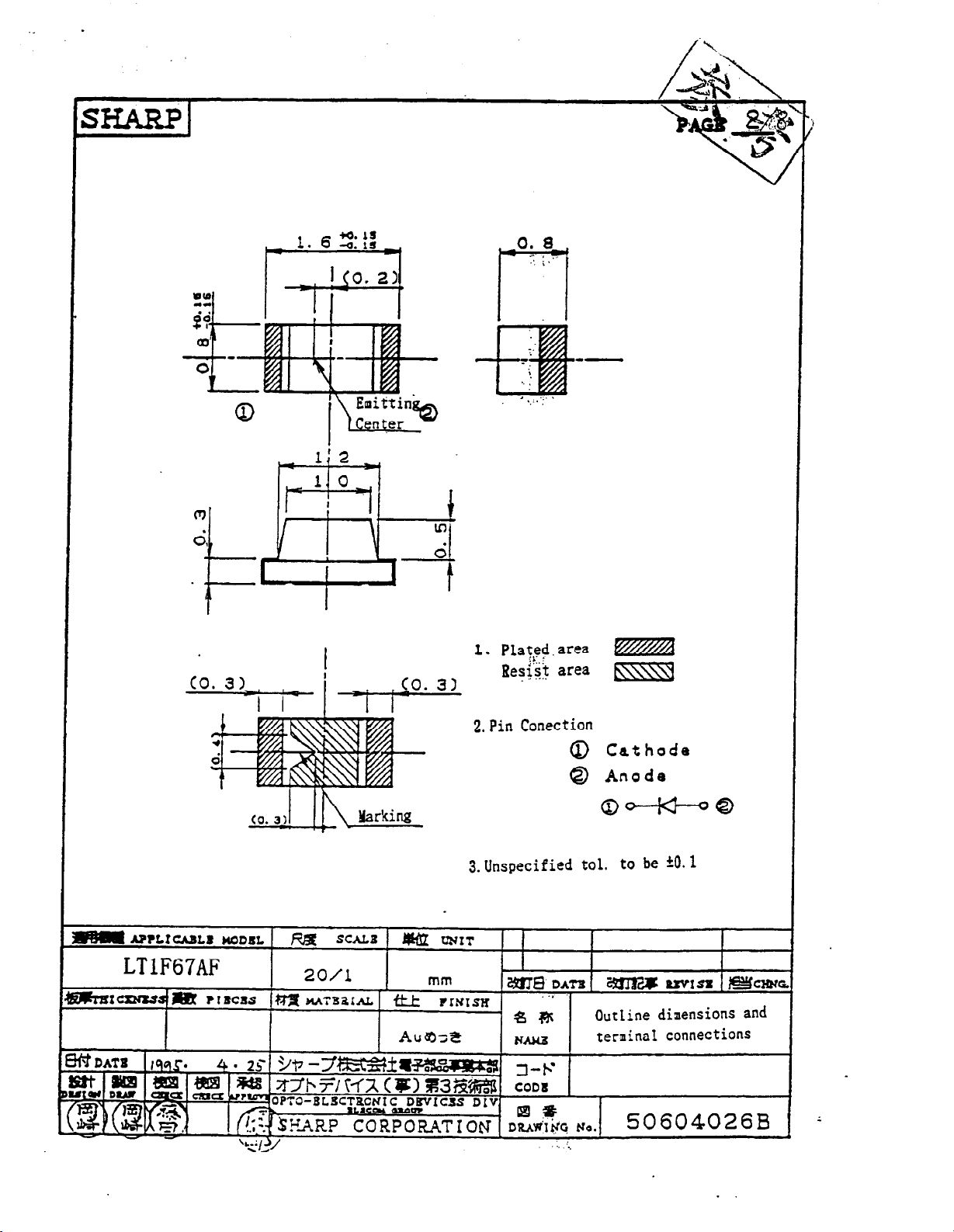
1. Plated.
j!:.;
ReqJ area
2.
Pin Conection
area
M
bxq
0 Cathode
@ Anode
0-0
3. Unspecified tel. to be
Outline dimensions and
terminal connections
iO.1
Page 4

1. This &tO 0h~t 10 to i*troduor thr lapin* sodi,i,fi~mlioO .Of LJ!U
* dcrlcc. lode1 Ho. LmwAF
2 taping
2. I tapiag rptciflc2tioo
2.2 Shipment table
spcciflcatlaa
.
‘SHIPMENT TABLE /-Hodel number
PA-IT NO.
QUANTITY
-Quantity of
- Lot amber* :
prodqcts
noi3[1oaaa
-m --v
LOT No. @ 0 ‘0 @ 8
SHARP
UADC IN JAI.4.Y
- Luminous intensity rank
. *:Lo e indication
0 Production plant code(to be indicated alphabetically)
$3 Production Lot(singie or double figures)
3 Year of producrion(che last tuo figures of
the year)
8 Konch of production
(to be indicated alphabetically with January corresponding to A)
d Date of production(Ol-31)
Page 5

2.3 Rcl+tcd l ttcrs
2.3.1. Packing
There should not be missing’rbova
2.3.2. true strength
1)Cover’trpe strength against peel iag: F=
continuous tbrte products.
0.1-O. 8N (I=lO*
or
Ied)
+-- Forward
2) Tape strength
The radius
If it .is less than 30aa.‘the
2.3.3. Taking
out of
11 Products should be
2) Products
2.3.4.. Jointing of true
There should not
3:
@anti
tp per reel
Average: 4.000 pcs.
against bending
of bending
products
should not
be
joint of cover tape or csrrier tape.
per reel
Cdneir tape
circ!e should
cover
easily
taken
be 30~ or aore.
tape may psi.
out.
be attached to the eover’taph rt txeling.
Page 6

4-1. Taping
4-1-I. Shape and diwnsion of tape(TYP. >
.
\/I
r3 -
: P2 ’
PI
-I
Parameter ~ysbol~imens iod Benarks
Concave square ‘fere icai
hole lot part
iasertion Pitch
Round
sprocket _
hole Position E
Center
cer dimension
Cover
Carrier
kickness of the entire
unit
3 i-taterial
Co
ten-
cape
tape Uidch
Horitoatal B
Diameter Da
Pitch
Vert.dire P2
Hori .dire F
Wid:h ( W,
Thickness 1 t3
Thickness 1 cl
Carrier
cape
A
1 1.1)am Dimeasioq excludes cocaes R
I 1.9mm
pi 1
PO
4. Omm
1. sala
4.Omn
1.75mm
2.omm
3.5ms
5.5mm 1
at inside
AccumuLa{:ed error
DistaaciI:becueen
Ceacer Line of
round
0. lnm [
1 wo
to
. ..PET. Cover tape...Polyescer
8. Omm ) .
0.2mm 1
1.2IIFA
With cover tape and carrier tape combined
bottom
. .
tape edge and hole center
the concave square hole and
sprocket hole
i0.5mm/lO
pitch
1
X--I
Page 7

a-l-2.Shapc and dimensian of reel (TYP. )
Parameter -
Diameter
Flange Thickness
Inner space direccioa 1 W
Hub
External
Spindle bale
Key
diameter E )6Qmm
diameter C
slit Width 1 E 1 2.0mm
Degch 1 U
Notation for part came etc.
3 Hatcrial: Reel.. .Polystyrene
1 Symbol } Dimension )’ &e@rks
I A
I c
Labeling on one side of f Lange.
I
9178mm
l.Smm
1anlm
+13fUlQ
4.5mm
Diqension of shaft
1 (Part name.quantity,loc No.)
core
Page 8

Packing Specification
In order to avoid the absorption of humidity in transport .a& storage, the~devices are
psdtcd in alusim0 skve.
4
1. Storage Conditions
The storage should lx done under follaaing conditions:
Temperature . 5 to 3oc
Humidity
less than 6OUl-l
2. Treatment after Opening
1)
Please
make a soldering within 2 days after opening under following conditions:
.-
Temperature 5 to 3OC
Humidity
less than 60;YRH
2) In case the devices are not used for a long time after opening, the storage in dq box
is recommendable. Or it is better to repack the devices with a desiccative by the
sealer
and put them in the same storage conditions as 6-I. Then they should be used rithin 2
W?XkS.
3) Please make a soldering after a following baking treatment if unused term should be
over the amditions of 2).
Remmendable Gmdi tions:
(TJ in taping
Tesprature 60t Time 90 to 100 Hours
@ in individual ( on PIB or metallic tray >
Temperature 11OC Time 3 to 4 Nours
Page 9

M aunt ing precautions
1. Soldering
l-1
Xeflow soldering
To be
doae’undet
the following conditiqa.
I
UN. EOse c
Recommendable T hermal M ode1
1-2 Reflow soldering precautions
Second time soldering
(Storage condition:at30C,RH(60%)
2. Soldering iron method
At 3OOC withln r seconds
When using a soldering iran.care must be taken not to damage the package
(Pay attion not to altou any undue stress or heat
shoufd be done witin 8 ham after the first one is l%shcd
ux. 5’5 ec
P3(
on package.)
1
Z
X-l
Page 10

LT1F67AF
 Loading...