

Page 1
FEATURES
■
Allows Dynamic Control of Output Frequency,
Cadence, Amplitude and DC Offset
■
Active Tracking Supply Configuration Allows Linear
Generation of Ring Tone Signal
■
No High Voltage Post-Filtering Required
■
Capacitive Isolation Eliminates Optocouplers
■
Low Distortion Output Meets International
PTT Requirements
■
Differential Input Signal for Noise Immunity
■
User Adjustable Active Output Current Limit
■
Powered Directly From High Voltage Ringer
Supply—No Additional Supplies Necessary
■
Supply Current: <1mA
■
2% Signal Amplitude Reference
■
Available in 14-Pin SO and DIP Packages
U
APPLICATIO S
■
Wireless Local Loop Telephones
■
Key System/PBX Equipment
■
Fiber to the Curb Telecom Equipment
LT1684
Micropower
Ring Tone Generator
U
DESCRIPTIO
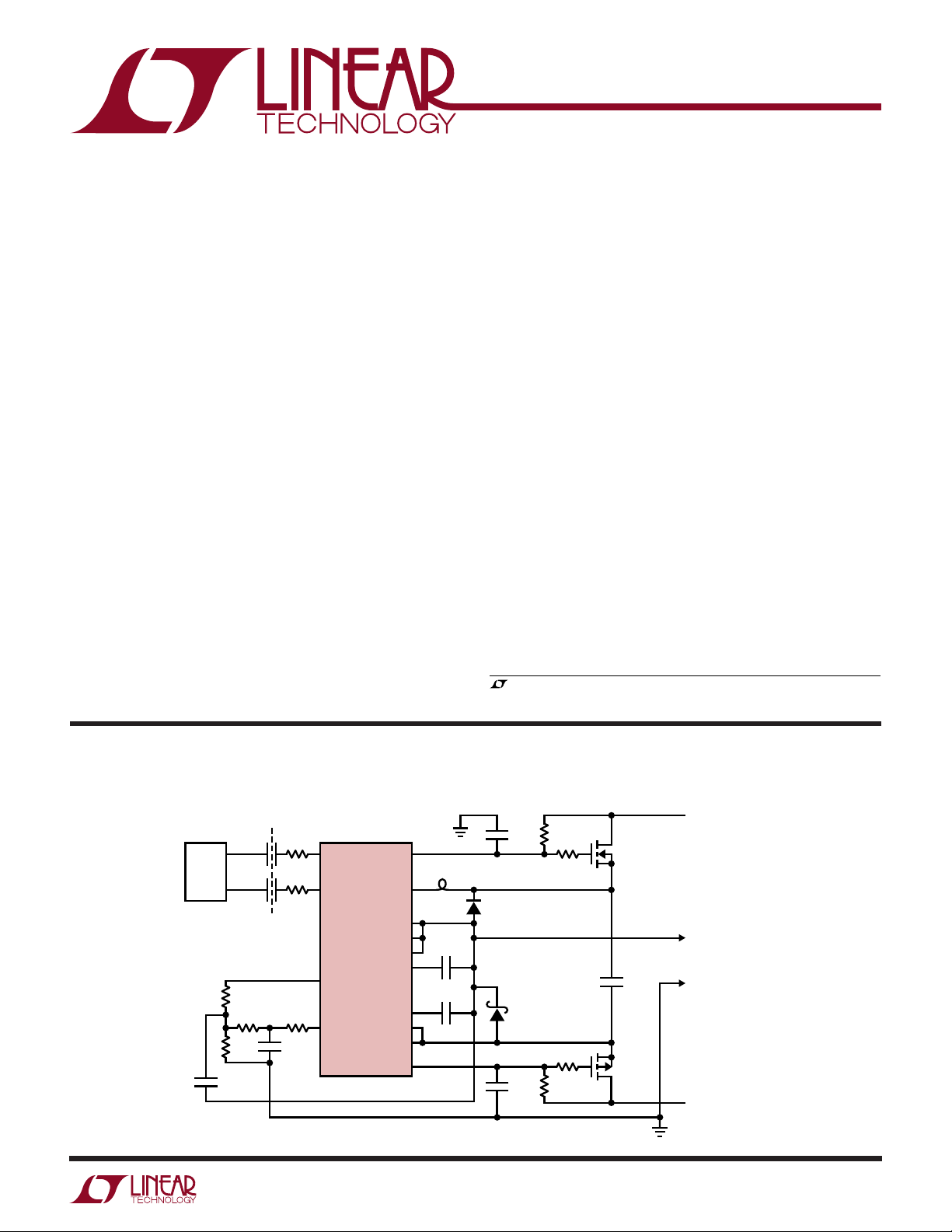
The LT®1684 is a telecommunication ring tone generator.
The IC takes a user-generated pulse width modulated
(PWM) input and converts it to a high voltage sine wave
suitable for telephone ringing applications.
The LT1684 receives capacitor-isolated differential PWM
input signals encoded with desired ring output cadence,
frequency, and amplitude information. The LT1684 normalizes the pulse amplitude to ±1.25V for an accurate
signal voltage reference. The cadence, frequency and
amplitude information is extracted using a multiplepole active filter/amplifier, producing the output ring tone
signal.
The LT1684 uses its own ring tone output as a reference
for generating local supply rails using complementary
high voltage external MOSFETs as dynamic level-shifting
devices. This “active tracking” supply mode of operation
allows linear generation of the high voltage ring tone
signal, reducing the need for large high voltage filtering
elements.
, LTC and LT are registered trademarks of Linear Technology Corporation.
TYPICAL APPLICATIO
1µF
ISOLATION
100pF
100pF
3k
2k
300k
DC
10k
10k
4700pF
PWM
CONTROLLER
P1
µC
P2
FB1: FERRONICS FMB1601 (716) 388-1020
U
5k
Electrically Isolated Ring Tone Generator
6.8nF
1N4001
1N5817
6.8nF
IN A GATE
IN B
LT1684
LIM
OUT
OUT
AT
COMP1
COMP2
GATE
BG
AMPIN LIM
REF
+
FB1
+
V
+
100pF
20pF
–
–
V
–
100k
100Ω
100Ω
100k
IRF610
0.1µF
IRF9610
100V
+
RING TONE
OUTPUT
–
–100V
1684 TA01
±100mA
()
CAPABILITY
1
Page 2

LT1684
WWWU
ABSOLUTE AXI U RATI GS
(Note 1)
Voltages:
Active Tracking Differential Voltage
(GATE+ – GATE–)..................................–0.3V to 42V
Local Supply Differential Voltage
(V+ – V–)...............................................–0.3V to 36V
Local Supply
Voltage V
+
..............
(GATE+ – 7.0V) to (GATE+ + 0.3V)
Local Supply
Voltage V
–
..............
(GATE– – 0.3V) to (GATE– + 7.0V)
PWM Input Differential Voltage
(IN A – IN B).........................................–7.0V to 7.0V
PWM Input Voltage
Common Mode................. (V– – 0.3V) to (V+ + 0.3V)
LIM+ Current Limit
Pin Voltage ..................... (OUT – 0.3V) to (V+ + 0.3V)
LIM– Current Limit
Pin Voltage .................... (V– – 0.3V) to (OUT + 0.3V)
All Other Pin Voltages ........... (V– – 0.3V) to (V+ + 0.3V)
UU
W
PACKAGE/ORDER I FOR ATIO
Currents:
LIM+, LIM– Current.......................................... –350mA
OUT Current ....................................................... 350mA
BG
Current .................................................... ±10mA
OUT
PWM (IN A, IN B) Current .................................... ±5mA
GATE+, GATE– Current .......................................±20mA
COMP1 Current .................................................... ±1mA
COMP2 Current .................................................... ±1mA
AT
Current ..................................................... ±20mA
REF
Temperatures:
Operating Junction Temperature Range
Commercial Grade................................. 0°C to 125°C
Industrial Grade................................ –40°C to 125°C
Storage Temperature Range ................. –65°C to 150°C
Lead Temperature (Soldering, 10 sec)..................300°C
TOP VIEW
1
IN B
2
COMP1
3
COMP2
–
4
LIM
–
5
V
–
6
GATE
7
AT
REF
N PACKAGE
14-LEAD PDIP
T
= 125°C, θ
JMAX
= 125°C, θ
T
JMAX
Consult factory for Military grade parts.
JA
JA
IN A
14
BG
13
OUT
AMPIN
12
+
GATE
11
+
V
10
+
LIM
9
OUT
8
S PACKAGE
14-LEAD PLASTIC SO
= 75°C/W (N)
= 115°C/W (S)
ORDER PART
NUMBER
LT1684CN
LT1684CS
LT1684IN
LT1684IS
2
Page 3

LT1684
ELECTRICAL CHARACTERISTICS
The ● denotes the specifications which apply over the full operating temperature range, otherwise specifications are at TA = 25°C.
V+ – V– = 20V, Voltages referenced to pin OUT, V
SYMBOL PARAMETER CONDITIONS MIN TYP MAX UNITS
Supply and Protection
I
S
|V+| Local Supply Voltages V
|V–|V
V
GATE
V
GATE
PWM Receiver
f
PWM
V
IN
R
IN
R
INA,INB
BG Buffer
V
BGOUT
V
BGOUTOS
I
BGOUTSC
R
BGOUT
t
r
t
f
∆t
r-f
t
pr
t
pf
∆t
p
Output Amplifier
V
OUTOS
R
OUT
I
OUTSC
DC Supply Current (Note 2) IN A – IN B ≥ 1.6V ● 680 950 µA
+ Active Tracking Supply FET I
Bias Voltage AT
– Active Tracking Supply FET I
Bias Voltage AT
Input Carrier Frequency 10 kHz
Minimum Valid Differential Input IN A – IN B or IN B – IN A ● 1.6 V
Differential Input Threshold ● 0.50 0.70 1.00 V
| IN A – IN B |
Differential Input Overdrive Impedance VIN > VTH + 100mV ● 710 kΩ
(Note 3, 5)
Single-Ended Input Impedance To Pin OUT ● 50 kΩ
(Note 5)
BG
Normalized Voltage Magnitude |V
OUT
Output Offset Voltage –7 7 mV
[(V
+) + (V
BGOUT
BG
Short-Circuit Current ● ±2 ±4.5 mA
OUT
BG
Output Impedance –2mA ≤ I
OUT
BG
Rise Time (10% to 90%) R
OUT
BG
Fall Time (10% to 90%) R
OUT
BG
RiseTime – Fall Time ● –200 –100 0 ns
OUT
BG
Propagation Delay PWM Input R
OUT
–)]/2 ● –10 10 mV
BGOUT
Transition to 10% Output (Rising Edge)
BG
Propagation Delay PWM Input R
OUT
Transition to 90% Output (Falling Edge)
BG
Propagation Delay ● – 200 –100 100 ns
OUT
Rising Edge – Falling Edge
OUT Offset Voltage V
OUT Output Impedance –10mA ≥ I
OUT Short-Circuit Current LIM+ Shorted to OUT ● ±100 ±190 mA
= V
OUT
GATE
GATE
+ = –100µA, ● 13.2 14.0 14.8 V
GATE
REF
– = 100µA, ● –14.8 –14.0 –13.2 V
GATE
REF
= 5k, C
OUT
= 5k, C
OUT
= 5k, C
OUT
= 5k, C
OUT
AMPIN
R
AMPIN
10mA ≤ I
LIM– Shorted to V
unless otherwise noted.
ATREF
+
+ ≥ V
– ≤ V
–
● 6.5 10 V
= 0V
= 0V
| 1.235 1.250 1.265 V
BGOUT
≤ 2mA 0.2 Ω
BGOUT
= 10pF ● 160 300 ns
OUT
= 10pF ● 260 400 ns
OUT
= 10pF ● 340 500 ns
OUT
= 10pF ● 440 600 ns
OUT
= 0v, I
= 0A – 6 6 mV
OUT
● 1.225 1.250 1.275 V
= 10k (Note 4) ● –8 8 mV
+ ≥ –100mA, LIM+ Shorted to OUT 0.01 Ω
LIM
≤ 100mA, LIM– Shorted to V
OUT
–
–
0.15 Ω
Note 1: Absolute Maximum Ratings are those values beyond which the life
of the device may be impaired.
Note 2: IC Supply current specification represents unloaded condition and
does not include external FET gate pull up/down currents (GATE
+
, GATE
–
pins). Actual total IC bias currents will be higher and vary with operating
conditions. See Applications Information.
Note 3: PWM inputs are high impedance through ±100mV beyond the
input thresholds.
Note 4: 10k resistor from pin AMPIN to ground.
Note 5: Guaranteed but not tested.
3
Page 4
LT1684
I
GATE
(mA)
0.1 0.3 1.0 3.0 10.0
V
GATE
– V
ATREF
(V)
1684 G03
14.3
14.2
14.1
14.0
13.9
13.8
TJ = 25°C
TEMPERATURE (°C)
–50 –25 0 25 50 75 100 125
V
BGOUT
(V)
1684 G06
1.253
1.252
1.251
1.250
1.249
1.248
1.247
1.246
1.245
R
LIM
(Ω)
0 21 4 6 83 5 7 910
OUTPUT CURRENT LIMIT (mA)
1684 G09
200
150
100
50
0
TYPICAL (TJ = 25°C)
MINIMUM (TJ = 125°C)
UW
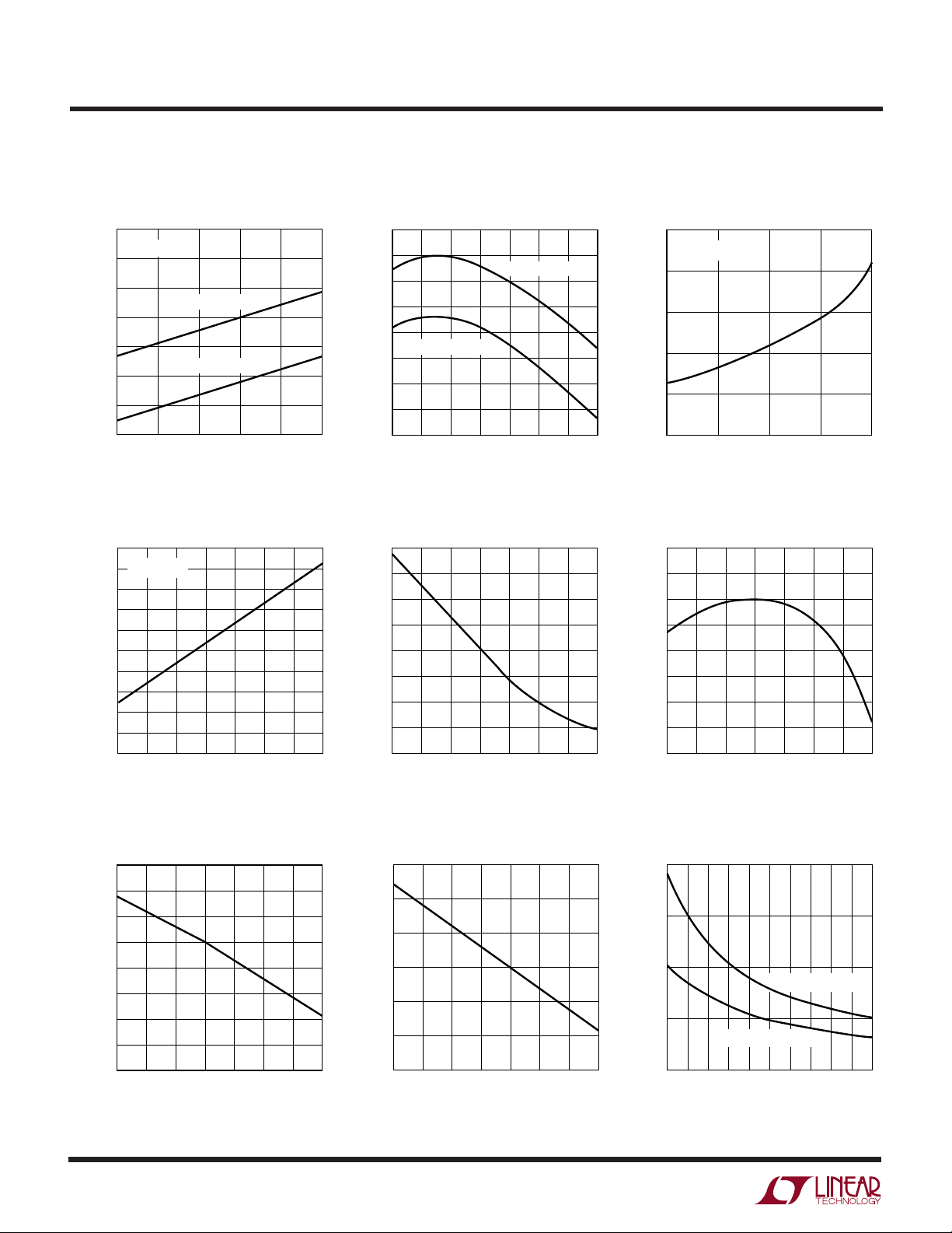
TYPICAL PERFOR A CE CHARACTERISTICS
DC Supply Current vs V+ – V
740
TJ = 25°C
720
700
680
660
640
DC SUPPLY CURRENT (µA)
620
600
14 16 18 20 22 24
V
GATE
IN A – IN B ≥ 1.6V
IN A – IN B ≤ –1.6V
– V
ATREF
V+ – V– (V)
Voltage
Magnitudes vs Temperature
14.5
I
= 1mA
GATE
14.4
14.3
14.2
(V)
14.1
ATREF
14.0
– V
13.9
GATE
13.8
V
13.7
13.6
13.5
–50 –25 0 25 50 75 100 125
TEMPERATURE (°C)
–
1684 G01
DC Supply Current vs Temperature
710
690
670
650
630
IN A – IN B ≤ –1.6V
610
590
DC SUPPLY CURRENT (µA)
570
550
–50 –25 0 25 50 75 100 125
TEMPERATURE (°C)
IN A – IN B ≥ 1.6V
PWM Input Thresholds vs
Temperature V
0.85
0.80
0.75
0.70
0.65
0.60
IN A – IN B (V)
0.55
0.50
0.45
–50 –25 0 25 50 75 100 125
1684 G04
TEMPERATURE (°C)
1684 G02
1684 G05
V
– V
GATE
Magnitudes vs I
BGOUT
Voltage
ATREF
GATE
Magnitude vs Temperature
PWM Buffer (Pin BG
Limit vs Temperature
6.0
5.5
5.0
4.5
4.0
3.5
3.0
2.5
PWM BUFFER CURRENT LIMIT (mA)
2.0
–50 –25 0 25 50 75 100 125
TEMPERATURE (°C)
4
OUT
) Current
1684 G07
Output Amplifier Current Limit vs
Temperature (R
250
225
200
175
150
OUTPUT CURRENT LIMIT (mA)
125
100
–50 –25 0 25 50 75 100 125
TEMPERATURE (°C)
LIM
= 0Ω)
Output Amplifier Current Limit vs
External Limiting Resistor Values
1684 G08
Page 5

LT1684
U
UU
PI FU CTIO S
IN B (Pin 1): PWM Negative Input. Input is isolated from
digital source by ~100pF series capacitor. A 10k resistor
can be connected to the IN B pin in series with the isolation
capacitor for transient protection. The PWM receiver implements a diode forward drop of input hysteresis (relative to
IN A). This hysteresis and internal signal limiting assure
common mode glitch rejection with isolation capacitor
mismatches up to 2:1. For maximum performance, however, effort should be made to match the two PWM input
isolation capacitors. Pin IN B is differentially clamped to
pin IN A through back-to-back diodes. This results in a
high impedance differential input through ±100mV beyond the input thresholds. 5k internal input resistors yield
a 10k (nominal) differential overdrive impedance.
COMP1 (Pin 2): Output Amplifier Primary Compensation.
Connect a 100pF capacitor from pin COMP1 to pin OUT.
COMP2 (Pin 3): Output Amplifier Secondary Compensation. Connect a 20pF capacitor from pin COMP2 to pin
OUT.
LIM– (Pin 4): Output Amplifier Current Sink Limit. Pin
implements I
resistor has a typical value of 3.5Ω. For maximum current
drive capability (190mA typical) short pin to pin V–.
Reduction of current sink capability is achieved by placing
additional resistance from pin LIM– to pin V–. (i.e. An
external 3.5Ω resistance from pin LIM– to pin V– will
reduce the current sinking capability of the output amplifier by approximately 50%.)
V– (Pin 5): Local Negative Supply. Typically connected to
the source of the active tracking supply P-channel MOSFET.
V– rail voltage is GATE– self-bias voltage less the MOSFET
VGS. Typical P-channel MOSFET characteristics provide
AT
– V– ≈ 10V.
REF
GATE– (Pin 6): Negative Power Supply FET Gate Drive. Pin
sources current from pull-down resistor to bias gate of
active tracking supply P-channel MOSFET. Self-biases to
a typical value of –14V, referenced to pin AT
resistor value is determined such that current sourced
from the GATE– pin remains greater than 50µA at mini-
mum output signal voltage and less than 10mA at maximum output signal voltage.
• R = VBE current clamp. Internal clamp
OUT
. Pull-down
REF
AT
(Pin 7): Active Tracking Supply Reference. Typi-
REF
cally connected to pin OUT. Pin bias current is the difference between the magnitudes of GATE+ pin bias and
GATE– pin bias (I
OUT (Pin 8): Ring Tone Output Pin. Output of active filter
amplifier/buffer. Used as reference voltage for internal
functions of IC. Usually shorted to pin AT
reference for active tracking supply circuitry. Connect a 1A
(1N4001-type) diode between V+ and OUT and a
1A Schottky diode from V– to OUT for line transient
protection.
LIM+ (Pin 9): Output Amplifier Current Source Limit. Pin
implements I
resistor has a typical value of 3.5Ω. For maximum current
drive capability (190mA typical) short pin LIM+ to pin
OUT. Reduction of current source capability is achieved by
placing additional resistance from pin LIM+ to pin OUT.
(i.e. An external 3.5Ω resistance from pin LIM+ to pin OUT
will reduce the current sourcing capability of the output
amplifier by approximately 50%.)
V+ (Pin 10): Local Positive Supply. Typically connected to
the source of the active tracking supply N-channel MOSFET.
This condition should be made using a ferrite bead.
Operating V+ rail voltage is GATE+ self-bias voltage less
the MOSFET VGS. Typical N-channel MOSFET characteristics provide V+ – AT
GATE+ (Pin 11): Positive Power Supply FET Gate Drive.
Pin sinks current from pull-up resistor to bias gate of
active tracking supply N-channel MOSFET. Self-biases to
a typical value of 14V, referenced to pin AT
resistor value is determined such that sink current into
GATE+ pin remains greater than 50µA at maximum output
signal voltage and less than 10mA at minimum output
signal voltage.
AMPIN (Pin 12): Output Amplifier Input. Connected to
external filter components through series protection resistor (usually 5k). Thevenin DC resistance of external
filter and protection components should be 10k for optimum amplifier offset performance. See Applications Information section.
OUT
= I
ATREF
• R = VBE current clamp. Internal clamp
≈ 10V.
REF
GATE
+ – I
–).
GATE
to generate
REF
REF
. Pull-up
5
Page 6

LT1684
U
UU
PI FU CTIO S
BG
(Pin 13): Normalized PWM Buffered Output. PWM
OUT
differential input is amplitude normalized to ±1.25V (refer-
enced to the OUT pin). This signal is used to drive the
active filter/amplifier. Filter resistor values must be chosen
to limit the maximum current load on this pin to less than
2mA. The output is current limit protected to a typical value
of ±4.5mA.
IN A (Pin 14): PWM Positive Input. Input is isolated from
digital source by ~100pF series capacitor. A 10k resistor
should be connected to the IN A pin in series with the
isolation capacitor for transient protection. The PWM
UU
W
FUNCTIONAL BLOCK DIAGRA
PWM
INPUT
100pF
+
100pF
–
IN A
IN B
BG
5k10k
5k10k
OUT
receiver implements a diode forward drop of input hysteresis (relative to IN B). This hysteresis and internal signal
limiting assure common mode glitch rejection with isolation capacitor mismatches up to 2:1. For maximum performance, however, effort should be made to match the two
PWM input isolation capacitors. Pin IN A is differentially
clamped to pin IN B through back-to back isolation-base
diodes. This results in a high impedance differential input
±100mV beyond the input thresholds. 5k internal input
resistors yield a 10k (nominal) differential overdrive impedance.
1.25V
+
V
–1.25V
+
V
+
GATE
FILTER
ELEMENTS
RING
OUTPUT
(RING RETURN)
100pF
20pF
AMPIN
COMP1
COMP2
–
5k
+
LT1684 Block Diagram
15k
CURRENT
LIMIT
14V
14V
AT
LIM
OUT
GATE
LIM
REF
+
–
–
–
V
–
V
1684 BD
6
Page 7

OPERATIO
LT1684
U
(Refer to Functional Block Diagram)
BASIC THEORY OF OPERATION
The LT1684 operates using a user-provided pulse-widthmodulated (PWM) digital signal as input*. The low frequency modulation component of this signal represents
the desired output waveform. Changing the PWM input
can thus dynamically control the frequency, cadence,
amplitude and DC offset of the desired output. This method
of sine wave generation can accomodate all popular ring
tone frequencies including 17Hz, 20Hz, 25Hz and 50Hz.
The LT1684 receives the PWM input by a capacitorisolated differential input at pins IN A and IN B. This signal
is amplitude normalized by a bandgap reference and
output single-ended on the BG
carrier is ±1.25V about the voltage on the OUT pin.
The low frequency component of the normalized PWM
signal is recovered using an active filter circuit constructed using an onboard driver amplifier. This amplifier
also provides current drive for the final ring tone output.
The ring tone output is used as the reference for a floating
active biasing scheme by pin AT
output rises and falls through its typical range of hundreds
of volts, the LT1684 “tracks” the output signal, maintaining local supply voltages across the IC of approximately
±10V.
Input Receiver/Reference Buffer
The differential receiver for the PWM input signal requires
minimum differential input levels of 1.6V to assure valid
change-of-state. The receiver inputs are capacitor coupled,
isolating the LT1684 from the PWM generator. The receiver is leading edge triggered.
The input receiver controls a switched-state output that
forces an amplitude normalized voltage (referenced to the
OUT pin) of ±1.25V that follows the PWM input. This
switched voltage is driven off-chip on pin BG
the IN A input is driven higher than IN B (by the required
pin such that the PWM
OUT
. As the ring tone
REF
OUT
. When
1.6V), the reference drives BG
When IN B input is driven higher than IN A, BG
to –1.25V relative to OUT.
The amplitude normalized representation of the input
PWM signal is used as the input for the active filter element
and output driver.
Output Amplifier/Driver
The normalized PWM signal output on the BG
converted to the final ring tone signal by an active filter.
This filter consists of an onboard amplifier and a few
external components. Although many different types of
filters can be constructed, a 2-pole Multiple Feedback
(MFB) configuration generally provides adequate performance and is desirable due to its simplicity and effectiveness.
The low frequency component of the ±1.25V PWM signal
contains the desired ring tone frequency and cadence
information. The MFB active filter strips this information
from the PWM signal and amplifies this low frequency
component to generate the final desired output.
Active Tracking Supplies
Implementation of the active tracking supply technique
enables linear generation of the ring tone output, and takes
advantage of the intrinsic supply noise immunity of a
linear amplifier, reducing the need for large high voltage
filtering elements.
Two external power MOSFETs act as voltage level-shifting
devices and generate the power supply voltages for the
LT1684. The LT1684 uses its own output as a voltage
reference for the FET level shifters, “suspending” itself (by
these generated supply voltages) about the signal output.
In this manner, the LT1684 can linearly generate a signal
hundreds of volts in amplitude at its output, while maintaining ±10V local supply rails across the IC itself.
to +1.25V above OUT.
OUT
is forced
OUT
OUT
pin is
* Contact Linear Technology for code.
7
Page 8

LT1684
WUUU
APPLICATIO S I FOR ATIO
Encoded PWM Signal Input Basics
The LT1684 accepts a user-supplied PWM carrier that
represents the desired output ring tone signal. This PWM
input is normalized by the LT1684 such that ring tone
output amplitudes can be accurately encoded into the
PWM input.
The LT1684 accepts a differential input to maximize rejection of system transients and ground noise. If no differential signal is readily available from the PWM controller, a
simple inverter/buffer block can be used to create the
differential signal required.
Each differential input is internally connected through a 5k
series resistor to back-to-back isolation-base diodes. These
devices internally clamp the differential input signal to
±100mV greater than the input comparator hysteresis
range. The input comparator toggles with a differential
hysteresis equal to that of a standard diode forward
voltage (0.7V nominal). As such, the differential impedance of the input remains high throughout the input
hysteresis region, then reduces to a nominal value of 10k
(7k minimum) as the input is overdriven beyond the
comparator input threshold. A minimum differential input
of 1.6V is specified to assure valid switching.
The PWM signal can be visualized in terms of instantaneous ring tone amplitude, normalized to the LT1684
amplitude reference. For a given desired output voltage
V
, the input pulse train required follows the relation:
OUTN
V
= 2 • V
OUTN
DC = [V
V
DC = PWM input duty cycle
OUTN
= 1.25V normalized peak voltage
REF
• (DC – 0.5), or
REF
/ (2 • V
)] + 0.5, where:
REF
A 10% to 90% duty cycle range is a practical limit for a
10kHz input carrier. This corresponds to normalized signal amplitude of ±1V. Duty cycles exceeding this range can
cause increased output signal distortion as signal energy
is lost due to finite rise and fall times becoming a significant percentage of the signal pulses. The associated
reduction in the pulse energy manifests itself as a “soft
clipping” of the output signal resulting in an increase in
harmonic distortion.
The normalized PWM signal is amplified to the desired
output signal level by the active filter/amplifier stage.
Thus, dividing the desired peak output amplitude by the
peak normalized encoded amplitude (V
the required DC gain of the active filter.
System Considerations
Assuming use of a 10% to 90% maximum PWM range, the
peak normalized signal will be:
V
(pk) = ± 0.8 • V
PWM
V
(pk) = V
OUT
Thus, the DC gain of the output filter equals the desired
peak voltage of the output ring tone signal.
The frequency characteristics of the lowpass output filter
must reflect the allowable carrier ripple on the output
signal. For example, a 10kHz carrier system could use a
2-pole Butterworth lowpass with a cutoff frequency of
100Hz. This filter provides 40dB of input signal rejection
at 10kHz yielding 25mV
the output filter/amplifier was 100, the output ripple voltage would be riding on a ±100V sine wave, and therefore
be about –78dB relative to the output ring signal.
(pk) • Filter DC Gain
PWM
= ±1.0V, and:
REF
output ripple. If the DC gain of
P-P
OUT/VOUTN
) yields
8
Page 9

WUUU
APPLICATIO S I FOR ATIO
LT1684
For applications that are extremely output ripple sensitive,
additional carrier rejection can be accomplished by modifying the output filter/amplifier characteristics such as
implementing elliptical filter characteristics with a lower
cutoff frequency or implementation of additional poles.
Filter Design and Component Selection
The ring tone information represented in the low frequency component of the input PWM signal is retrieved
using an active filter. This filter also generates the appropriate low frequency gain required to produce the high
voltage output signal and references the output to ground
(or other system reference). The frequency and gain
characteristics of this circuit element are both configurable
by the appropriate choice of external passive filter elements. Because of the active tracking supply mode of
operation, conventional active filter topologies cannot be
used. Most amplifier/filter topologies can, however, be
“transformed” into active tracking supply topologies.
A conventional amplifier circuit topology can be “transformed” into an active tracking supply amplifier circuit by:
a) Inverting the amplifier signal polarity (swap amplifier +
and – connections) and input source polarity.
b) Referencing all signals to the output except the feedback elements, which are referenced to ground (swap
output and ground).
A variety of amplifier/filter configurations can be realized
using the transformation technique. A 2-pole filter is
generally adequate for most ringer applications. Due to the
relative simplicity of infinite-gain Multiple Feedback (MFB)
configurations, these filters are good candidates for ringer
applications. Component selection and active tracking
supply transformation will be described for the following
2-pole MFB infinite-gain lowpass filter.
Conventional Amplifier Configuration Active Tracking Supply Amplifier
R1 R2
+
V
IN
–
Lowpass Mulitple Feedback Active Filter Active Tracking Supply Lowpass
R1 R3
+
V
IN
–
–
+
LOAD
C2R2
–
C1
+
TRANSFORMATION
TRANSFORMATION
LOAD
+
V
IN
–
R1
Multiple Feedback Filter
+
V
IN
–
R2
–
+
R2
C1
R3R1
C2
–
+
LOAD
LOAD
1684 F01
9
Page 10

LT1684
HERTZ (Hz)
1 10 100 1K 10K 100K
FILTER GAIN (dB)
1684 F02
–50
0
50
WUUU
APPLICATIO S I FOR ATIO
The component selections for the active tracking supply
lowpass MFB filter configuration follow the relations:
C2 = mC
R2 = 1± [1–4mQ2(1+|HO|)]
m ≤ 1 / [4Q2(1+|HO|)]
1
1/2
2ωnC1mQ
R1 = R2 / |HO|
R3 =1
2
2
ω
C
R2m
n
1
Example:
Conditions: Output ring tone peak voltage = 100V
Ring frequency = 20Hz
Input duty cycle range = 10% to 90%
Filter Q = 0.707
Set: fn = ωn / 2π = 100Hz
Choose: C1 = 1.0µF (a convenient value)
Then: m ≤ [4(0.7)2(1+100)]–1 ≈ .005
Active Tracking Supply Lowpass Multiple
Feedback Filter Transfer Characteristic (AV vs fn)
However, bootstrapping an amplifier system about its
own output creates a complex myriad of inherent stability
and response issues. Attempting such a configuration
with generic “jelly-bean” components is not recommended
for the faint of heart or type-A personalities. The LT1684,
however, makes for a simplistic approach to active tracking component selection.
This filter configuration yields a DC Gain of 100, a corner
frequency of just under 100Hz with gain reduction of only
0.1% at 20Hz, and a 10kHz carrier rejection of greater than
40dB at the output.
Active Tracking Supply Components
Given the previous discussion, implementation of an
active tracking supply system may seem almost trivial.
C2 = mC1 C2 = 4700pF
(sets m = 0.0047)
R2 = 1± [1–4(0.0047)(0.707)2(101)]
1/2
(4π100)(1e–6)(.0047)(0.707)
R2 = 300k
R1 = 300k/100
R1 = 3.0k
R3 = [(2π100)2(1e–6)2(300k)(0.0047)]
R3 = 2k
–1
The high voltage MOSFET transistors used in the circuit
must have an operating VDS specified at greater than the
corresponding high voltage supply rail plus the opposite
maximum excursion of the output signal. For example, if
a system is designed with a 240V supply (+120V,
–120V) and outputs a ring signal that has a 100V peak
amplitude, the MOSFET VDS ratings must be greater than
240/2 + 100 = 220V.
Active Filter Tuned Oscillator—
No PWM Input Required
A simple yet effective method of producing a high quality
sine wave is to place a high-Q bandpass filter and a hard
limited gain element in a positive feedback loop. This
circuit will oscillate at the bandpass frequency, producing
a sine wave at the filter output. The product of the fundamental component of the limiter and the filter gain at the
bandpass frequency determines the output amplitude.
This type of circuit is commonly referred to as an active
filter tuned oscillator.
10
Page 11

WUUU
APPLICATIO S I FOR ATIO
LT1684
Active Filter Tuned Oscillator Block Diagram
1684 F03
The LT1684 can be implemented easily into a telephone
ringer circuit based on the active filter tuned oscillator
topology, eliminating the need for a user-supplied PWM
input signal. The LT1684’s active filter amplifier can be
used as a high-Q bandpass filter element by configuring
it as an active tracking supply bandpass. The LT1684’s
controlled output receiver/buffer is also convenient for
use as the hard limiter. Because the LT1684 receiver/
buffer requires a true differential input for proper operation, a dual comparator IC such as the LT1017 must be
bootstrapped along with the LT1684 to provide differential control signals. The LT1017 and LT1684 receiver/
buffer combine to create a high gain hard limiter whose
output is controlled to ±1.25V. The LT1684 active
bandpass filter is then connected as a positive feedback
element with the limiter component, which completes
the active filter tuned oscillator topology.
The active bandpass filter circuit is easily configured using
a basic MFB bandpass configuration, however, the active
tracking supply technique used by the LT1684 requires
“transformation” of this topology. This “transformation”
swaps the amplifier signal polarity, references all signals
to the output, and references all feedback elements to
ground as described previously in the Filter Design and
Component Selection section.
The design equations for the active tracking bandpass
filter are the same as the pretransformation MFB topology,
such that if CF1 = CF2 = C:
RF1 = Q/(ωO • C •H0)
RF2 = Q/(2Q2 –H0)(ωO • C)
RF3 = 2Q/(ωO • C)
Example:
Conditions: Output peak voltage = 95V
Bandpass MFB Filter
C
F2
R
F3
R
F1
C
F1
+
V
IN
R
–
Active Tracking Bandpass MFB Filter
F2
R
F1
R
F2
C
F1
C
F2
–
+
+
–
V
IN
–
+
R
F3
V
OUT
1684 F5b
V
OUT
1684 F4a
Ring frequency = 20Hz
Bandpass Q = 9.4
A square wave with peak amplitude A has a fundamental
component with amplitude 4A/π, where A = 1.25V. Therefore, the desired filter’s bandpass gain HO = 95/(4 •
1.25/π) ~ 60. Given capacitor values C = 0.22µF (a conve-
nient value) and desired filter characteristics of: Q = 9.4,
HO = 60, ωO = 2π(20Hz), then: RF1 = 5.6k, RF2 = 2.7k,
RF3 = 680k. The amplitude, frequency and envelope response time of the output signal can be adjusted by simply
changing the values of resistors RF1 to RF3 accordingly.
This produces a high voltage, high quality 20Hz sine wave
at the filter output with a peak amplitude of 95V. Differential amplitude and frequency characteristics are achieved
by simply changing a few resistor values. The output of the
LT1684 is internally current limited to a minimum of
±100mA peak, allowing this ring tone generation circuit to
be used with loads up to 7 REN with no degradation of the
output waveform.
11
Page 12

LT1684
WUUU
APPLICATIO S I FOR ATIO
Active Filter Tuned Oscillator Ring Tone Generator
110V
8
5
+
+
V
C2
100pF
D1
1N5817
R10
10k
C1 20pF
1
2
3
4
5
6
7
7
IN B
COMP1
COMP2
LIM
–
V
GATE
AT
REF
1/2 LT1017
–
4
LT1684
–
–
IN A
BG
OUT
AMPIN
GATE
LIM
OUT
–
V
R9
10k
6V
R8
10k
14
13
12
11
+
10
+
9
+
R
F3
8
680k
C
C
F1
F2
0.22µF
0.22µF
1
8
+
V
1/2 LT1017
–
V
4
R
F1
5.6k
R
F2
2.7k
3
+
R6
1k
2
–
R5
100k
R3
100k
R2
100Ω
FB1
C4
6.8nF
C3
6.8nF
M1
IRF610
C5
0.1µF
D2
1N4001
+
OUTPUT
–
±100mA
()
PEAK
–110V
FB1: FERRONICS FMB1601 (716) 388-1020
Ringer Output
R4
100k
R1 100Ω
M2
IRF9610
1684 F05a
12
Page 13

TYPICAL APPLICATIO S
U
M1
IRF610
D1
1N4001
C3
LT1684
+
–
OUTPUT
0.1µF
M2
IRF9610
1684 TA03
C14
+
876
LT1017
123
R2 10k
10µF
160V
CC
V
OUT A
OUT B
–IN A
–IN B
+IN A
C15
+
5
+IN B
EE
V
4
R1
R8
10µF
1k
100k
160V
R3
R4 10k
10k
14
IN A
IN B
1
C6
R7
100pF
100k
13
BG
COMP1
2
R6
12
OUT
3
C5 20pF
FB1
100Ω
11
10
+
+
GATE
AMPIN
LT1684
COMP2
LIM–V–GATE–AT
4
5
DS1
F1
R
V
1N5817
10k
R10
91V
DZ2
F3
R
680k
620k
F2
R
2.7k
3.3k
F1
R
5.6k
6.8k
95V
70V
V (PEAK)
7
10
LOAD (REN)
R
6.8nF
F2
2.7k
DZ4
91V
R5 100Ω
R14
100k
10k
R12
50k
R13
15
2
C2
6.8nF
5.6k
0.22µF
F1
C
9
+
LIM
6
15
R11
C1
0.22µF
F2
C
F3
R
680k
8
OUT
REF
7
50k
2
C11
0.47µF
160V
C12
0.47µF
160V
3
4
OPTO2 H11AG1
6
C10
0.1µF
C13
0.01µF
R15
4
2k
FB1: FERRONICS FMB1601 (716) 388-1020
D4
MURS160
C9
0.47µF
2
•
T1
5V-15V to Ring Tone Fully Isolated Converter Using an Active Filter-Tuned Oscillator Circuit
COILTRONICS
160V
1
14239-X3
12
•
5, 6
C7
D2
MURS160
220µF
10V
11
7, 8
•
49
D3
DZ1
1N4001
44V
R9
39Ω
C8
1nF
OPTO1 H11AG1
DS2
4
SW
IN
V
5
C4
1µF
6
MBRS1100
1
C
V
LT1270
FB
2
GND
+
INPUT
5V TO 15V
13
Page 14

LT1684
TYPICAL APPLICATIO S
U
5kW PWM-to-Analog Converter
300k
120V
6800pF
1000pF
10k
14
PWM
1000pF
IN
3k
0.1µF
FB1: FERRONICS FMB1601 (716) 388-1020
10k
2k
470pF
IN A
1
IN B
13
BG
5k
12
AMPIN
6800pF
OUT
GATE
LT1684
GATE
–120V
100k
11
+
COMP1
COMP2
–
6
100Ω
LIM
AT
LIM
100k
V
OUT
REF
V
100Ω
1nF
IN
1nF
V
LT1166
V
BOTTOM
47Ω
2N3906
1
TOP
SENSE
SENSE
4
2N3904
47Ω
100Ω
8
+
7
+
I
LIM
3
V
OUT
6
–
I
LIM
5
–
100Ω
TYPICAL POWER SLICE
(1 OF 13 IN PARALLEL)
100V
IRF230
1k
0.22Ω
1µF
1µF
0.22Ω
1k
IRF9240
–100V
0.22Ω
1µH
1684 TA04
5kW
LOAD
3.9k
180µH
100Ω
2
V
100Ω
2N3906
MTP2N50E
FB1
10
+
2
9
+
8
7
3
4
–
5
–
100pF
MTP2N50E
20pF
180µH
2k
2N3904
14
Page 15

PACKAGE DESCRIPTIO
U
Dimensions in inches (millimeters) unless otherwise noted.
N Package
14-Lead PDIP (Narrow 0.300)
(LTC DWG # 05-08-1510)
0.770*
(19.558)
MAX
14
0.255 ± 0.015*
(6.477 ± 0.381)
11
1213
8910
LT1684
0.300 – 0.325
(7.620 – 8.255)
0.009 – 0.015
(0.229 – 0.381)
+0.035
0.325
–0.015
+0.889
8.255
()
–0.381
*THESE DIMENSIONS DO NOT INCLUDE MOLD FLASH OR PROTRUSIONS.
MOLD FLASH OR PROTRUSIONS SHALL NOT EXCEED 0.010 INCH (0.254mm)
0.020
(0.508)
MIN
0.130 ± 0.005
(3.302 ± 0.127)
0.125
(3.175)
MIN
0.005
(0.125)
MIN
S Package
14-Lead Plastic Small Outline (Narrow 0.150)
(LTC DWG # 05-08-1610)
13
14
2
31
0.045 – 0.065
(1.143 – 1.651)
0.100
(2.54)
BSC
0.337 – 0.344*
(8.560 – 8.738)
12
6
9
7
0.065
(1.651)
TYP
0.018 ± 0.003
(0.457 ± 0.076)
N14 1098
8
5
4
11
10
0.228 – 0.244
(5.791 – 6.197)
0.010 – 0.020
(0.254 – 0.508)
0.008 – 0.010
(0.203 – 0.254)
*
DIMENSION DOES NOT INCLUDE MOLD FLASH. MOLD FLASH
SHALL NOT EXCEED 0.006" (0.152mm) PER SIDE
**
DIMENSION DOES NOT INCLUDE INTERLEAD FLASH. INTERLEAD
FLASH SHALL NOT EXCEED 0.010" (0.254mm) PER SIDE
× 45°
0° – 8° TYP
0.016 – 0.050
(0.406 – 1.270)
Information furnished by Linear Technology Corporation is believed to be accurate and reliable.
However, no responsibility is assumed for its use. Linear Technology Corporation makes no representation that the interconnection of its circuits as described herein will not infringe on existing patent rights.
0.053 – 0.069
(1.346 – 1.752)
0.014 – 0.019
(0.355 – 0.483)
TYP
0.150 – 0.157**
(3.810 – 3.988)
1
3
2
4
0.050
(1.270)
BSC
5
7
6
0.004 – 0.010
(0.101 – 0.254)
S14 1298
15
Page 16

LT1684
TYPICAL APPLICATIO
V
IN
PWM
INPUT
5V
+
–
C1
100pF
C3 100pF
C4 20pF
C2
100pF
R4
10k
IN B
COMP1
COMP2
–
LIM
–
V
GATE
AT
REF
LT1684
–
IN A
BG
OUT
AMPIN
GATE
LIM
OUT
R2
10k
R3
5k
+
FB1
+
V
D1
1N4001
+
1µF
U
5V Input Nonisolated 5 REN Ring Generator
100V
D2
MURS160T3
C11
IRF610
+
0.47µF
160V
+
C10
0.47µF
160V
D3
MURS160T3
M1
MBRS1100
DZ1
60V
MMSZ5264BT1
R10
100k
R8
100Ω
C8
300k
R1
2k
C5
R5
4700pF
R6
3k
C7
6.8nF
160V
C6
6.8nF
160V
T1
COILTRONICS
CTX 14468-X1
12
•
10
9
•
•
7
DS1
4, 5
1, 2
4
1
R11
470Ω
SW
V
C
C9
0.1µF
+
U1
LT1271
GND
C12
220µF
35V
5
V
IN
R12
5k
2
FB
3
R7
100Ω
DS2
D1N5817
FB1: FERRONICS FMB1601 (716) 388-1020
M2
IRF9610
R9
100k
C13 0.1µF
–100V
R16
1M
R15
12k
RING TONE
OUT
D4
D1N4148
LT1211
1
OUT A
–IN A
V
EE
V
OUT B
–IN B+IN A
+IN B
27
36
4
D5
8
CC
D1N4148
5
1684 TA02
R14
1M
R13
12k
RELATED PARTS
PART NUMBER DESCRIPTION COMMENTS
LT1082 1A High Voltage Switching Regulator VIN = 3V to 75V, SW Voltage = 100V
LT1166 Power Output Stage Automatic Bias System Sets Class AB Bias Currents, Eliminates Adjustments
and Thermal Runaway
LTC1177-5/LTC1177-12 Isolated MOSFET Drivers 2500V
LT1270 8A Power Switching Regulator VIN = 3.5V to 30V, IQ = 7mA
LT1271 4A Power Switching Regulator VIN = 3.5V to 30V, IQ = 7mA
LT1339 High Power Synchronous DC/DC Controller Operation Up to 60V, Output Current Up to 50A
LT1676 Wide Input Range, High Efficiency, Step-Down Switching Regulator Operation Up to 60V, 100kHz, Up to 500mA Output
Isolation, UL Recognized
RMS
16
Linear Technology Corporation
1630 McCarthy Blvd., Milpitas, CA 95035-7417
(408) 432-1900 ● FAX: (408) 434-0507
●
www.linear-tech.com
1684f LT/TP 0300 4K • PRINTED IN USA
LINEAR TECHNOLOGY CORPORATION 1999
 Loading...