

Page 1
LT1173
Micropower
DC/DC Converter
Adjustable and Fixed 5V, 12V
EATU
F
■
Operates at Supply Voltages From 2.0V to 30V
■
Consumes Only 110µA Supply Current
■
Works in Step-Up or Step-Down Mode
■
Only Three External Components Required
■
Low Battery Detector Comparator On-Chip
■
User-Adjustable Current Limit
■
Internal 1A Power Switch
■
Fixed or Adjustable Output Voltage Versions
■
Space Saving 8-Pin MiniDIP or SO8 Package
PPLICATI
A
■
Flash Memory Vpp Generators
■
3V to 5V, 5V to 12V Converters
■
9V to 5V, 12V to 5V Converters
■
LCD Bias Generators
■
Peripherals and Add-On Cards
■
Battery Backup Supplies
■
Laptop and Palmtop Computers
■
Cellular Telephones
■
Portable Instruments
RE
S
O
U
S
DUESCRIPTIO
The LT1173 is a versatile micropower DC-DC converter.
The device requires only three external components to
deliver a fixed output of 5V or 12V. Supply voltage ranges
from 2.0V to 12V in step-up mode and to 30V in step-down
mode. The LT1173 functions equally well in step-up, stepdown or inverting applications.
The LT1173 consumes just 110µA supply current at
standby, making it ideal for applications where low quiescent current is important. The device can deliver 5V at
80mA from a 3V input in step-up mode or 5V at 200mA
from a 12V input in step-down mode.
Switch current limit can be programmed with a single
resistor. An auxiliary gain block can be configured as a low
battery detector, linear post regulator, under voltage lockout circuit or error amplifier.
For input sources of less than 2V, use the LT1073.
and LTC are registered trademarks and LT is a trademark of Linear Technology Corporation.
O
PPLICATITYPICAL
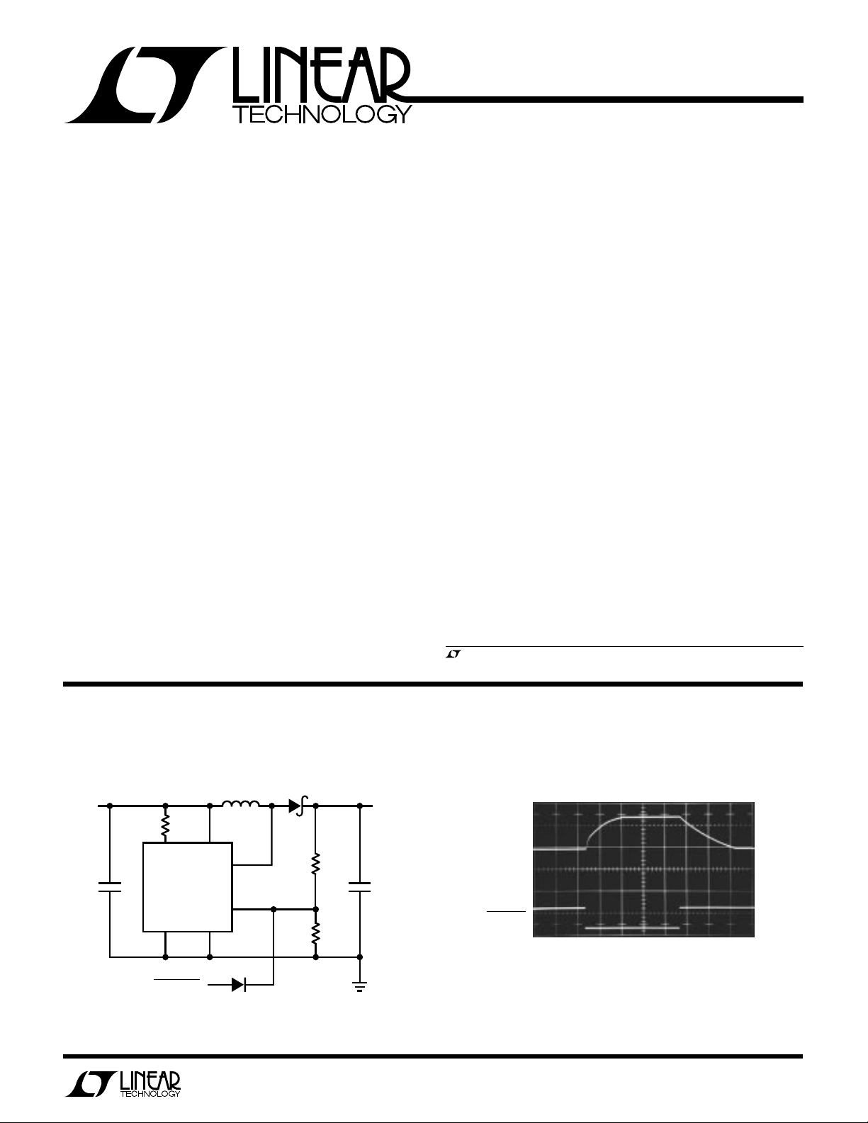
Logic Controlled Flash Memory VPP Generator
5V
IN
+
10 F
µ
*L1 = GOWANDA GA20-103K
COILTRONICS CTX100-4
NO OVERSHOOT
47Ω
V
I
LIM
GND SW2
PROGRAM
IN
LT1173
SW1
100µH
FB
1N4148
L1*
1N5818
EFFICIENCY = 81%
†
= 1% METAL FILM
U
SA
1.07M
124k
VPP Output
12V
100mA
V
OUT
5V/DIV
†
SANYO
+
OS-CON
µ
100 F
†
LT1173 • TA01
0V
PROGRAM
5V/DIV
5ms/DIV
1173 TA02
1
Page 2
LT1173
WU
U
PACKAGE
/
O
RDER I FOR ATIO
A
W
O
LUTEXI T
S
A
WUW
ARB
U
G
I
S
Supply Voltage (VIN)................................................ 36V
SW1 Pin Voltage (V
SW2 Pin Voltage (V
) .......................................... 50V
SW1
) .............................–0.5V to V
SW2
IN
Feedback Pin Voltage (LT1173) ................................. 5V
Sense Pin Voltage (LT1173, -5, -12) ....................... 36V
Maximum Power Dissipation ............................. 500mW
Maximum Switch Current ....................................... 1.5A
Operating Temperature Range ..................... 0°C to 70°C
Storage Temperature Range .................. –65°C to 150°C
Lead Temperature, (Soldering, 10 sec.)................300°C
Consult factory for Industrial and Military grade parts
I
1
LIM
V
2
IN
SW1
3
SW2
4
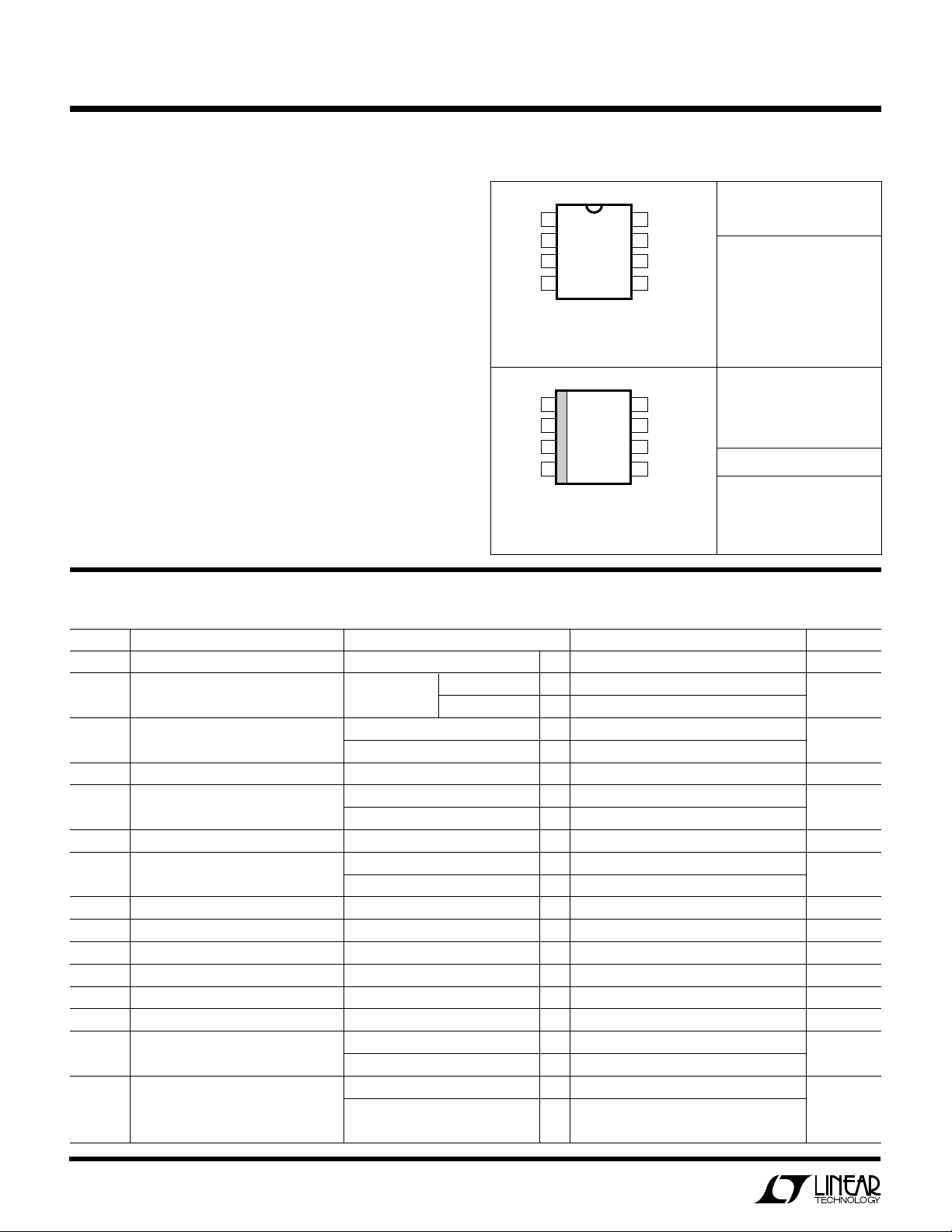
N8 PACKAGE
8-LEAD PLASTIC DIP
*FIXED VERSIONS
T
= 90°C, θJA = 130°C/W
JMAX
I
1
LIM
V
2
IN
SW1
3
SW2
4
S8 PACKAGE
8-LEAD PLASTIC SOIC
*FIXED VERSIONS
T
= 90°C, θJA = 150°C/W
JMAX
TOP VIEW
TOP VIEW
FB (SENSE)*
8
SET
7
AO
6
GND
5
FB (SENSE)*
8
SET
7
AO
6
GND
5
ORDER PART
NUMBER
LT1173CN8
LT1173CN8-5
LT1173CN8-12
LT1173CS8
LT1173CS8-5
LT1173CS8-12
S8 PART MARKING
1173
11735
117312
LECTRICAL C CHARA TERIST
E
SYMBOL PARAMETER CONDITIONS MIN TYP MAX UNITS
I
I
V
V
f
t
V
V
Q
Q
IN
OUT
OSC
ON
OL
SAT
Quiescent Current Switch Off ● 110 150 µA
Quiescent Current, Boost No Load LT1173-5 135 µA
Mode Configuration
Input Voltage Step-Up Mode ● 2.0 12.6 V
Comparator Trip Point Voltage LT1173 (Note 1) ● 1.20 1.245 1.30 V
Output Sense Voltage LT1173-5 (Note 2) ● 4.75 5.00 5.25 V
Comparator Hysteresis LT1173 ● 510 mV
Output Hysteresis LT1173-5 ● 20 40 mV
Oscillator Frequency ● 18 23 30 kHz
Duty Cycle Full Load ● 43 51 59 %
Switch ON Time I
Feedback Pin Bias Current LT1173, VFB = 0V ● 10 50 nA
Set Pin Bias Current V
Gain Block Output Low I
Reference Line Regulation 2.0V ≤ VIN ≤ 5V ● 0.2 0.4 %/V
SW
Voltage, Step-Up Mode VIN = 3.0V, ISW = 650mA ● 0.5 0.65 V
SAT
ICS
TA = 25°C, VIN = 3V, unless otherwise noted.
LT1173-12 250 µA
Step-Down Mode ● 30 V
LT1173-12 (Note 2) ● 11.4 12.0 12.6 V
LT1173-12 ● 50 100 mV
tied to V
LIM
SET
SINK
5V ≤ VIN ≤ 30V ● 0.02 0.075 %/V
VIN = 5.0V, ISW = 1A 0.8 1.0 V
IN
= V
REF
= 100µA, V
= 1.00V ● 0.15 0.4 V
SET
● 17 22 32 µs
● 20 100 nA
● 1.4 V
2
Page 3
LT1173
TEMPERATURE (°C)
–50
FEEDBACK PIN BIAS CURRENT ( A)
14
16
18
–25 0 25 50
LT1173 •TPC05
75
100
125
V = 3V
IN
µ
12
10
8
R ( )
10
100
SWITCH CURRENT (mA)
400
800
1200
100
LT1173 • TPC03
Ω
1000
900
700
600
500
300
200
LIM
1000
1100
2V ≤ VIN ≤ 5V
LECTRICAL C CHARA TERIST
E
ICS
TA = 25°C, V
= 3V, unless otherwise noted.
IN
SYMBOL PARAMETER CONDITIONS MIN TYP MAX UNITS
V
SAT
A
V
SW
Voltage, Step-Down Mode VIN = 12V, ISW = 650mA 1.1 1.5 V
SAT
● 1.7 V
Gain Block Gain RL = 100kΩ (Note 3) ● 400 1000 V/V
Current Limit 220Ω to I
LIM
to V
IN
400 mA
Current Limit Temperature Coeff. ● –0.3 %/°C
Switch OFF Leakage Current Measured at SW1 Pin 1 10 µA
V
SW2
The ● denotes the specifications which apply over the full operating
temperature range.
Note 1: This specification guarantees that both the high and low trip points
of the comparator fall within the 1.20V to 1.30V range.
Maximum Excursion Below GND I
≤ 10µA, Switch Off –400 –350 mV
SW1
Note 2: The output voltage waveform will exhibit a sawtooth shape due to
the comparator hysteresis. The output voltage on the fixed output versions
will always be within the specified range.
Note 3: 100kΩ resistor connected between a 5V source and the AO pin.
UW
Y
PICA
1.2
LPER
F
O
R
AT
CCHARA TERIST
E
C
ICS
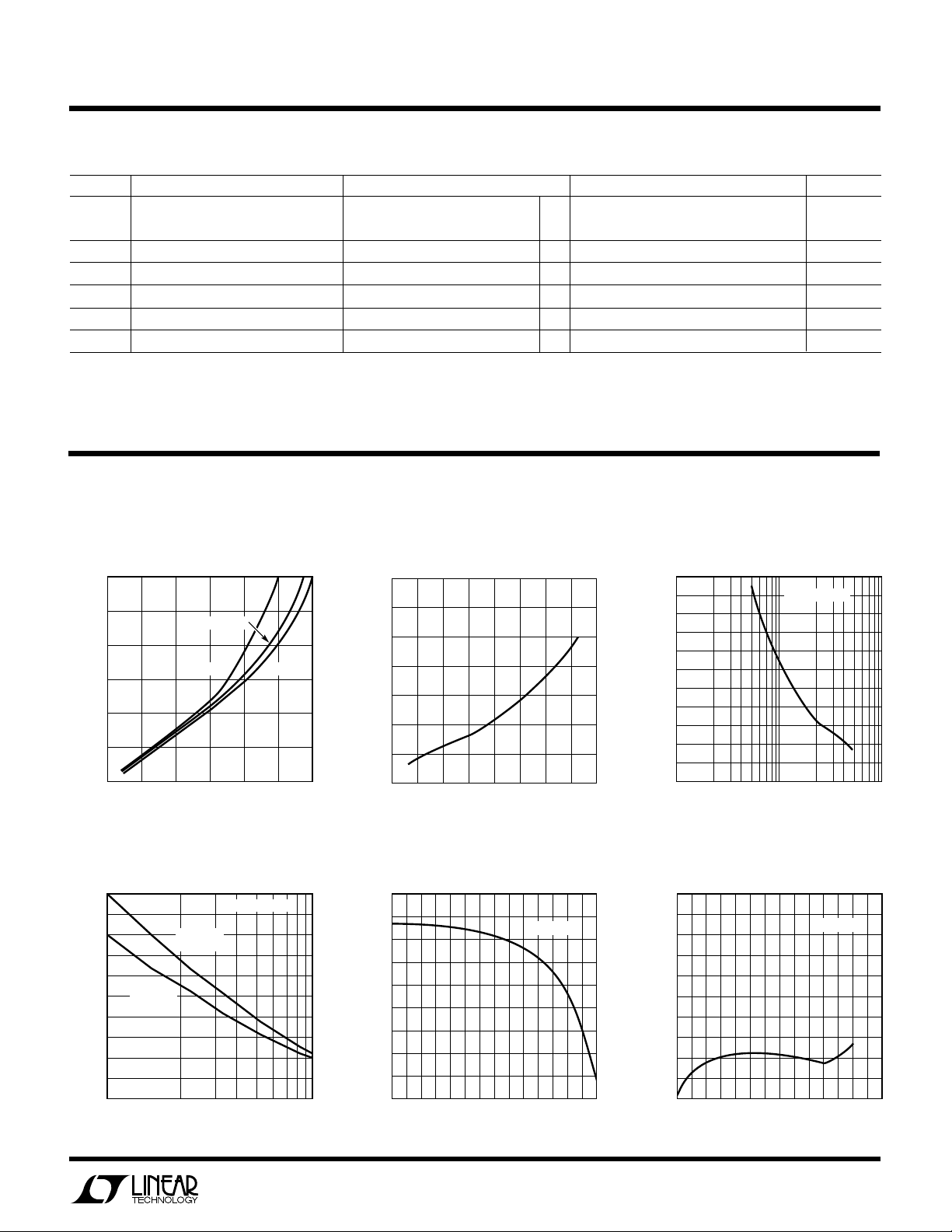
Switch ON Voltage
Saturation Voltage Step-Up Mode Step-Down Mode Maximum Switch Current vs
(SW2 Pin Grounded) (SW1 Pin Connected to VIN)R
1.4
Step-Up Mode
LIM
1.0
0.8
0.6
CESAT
V (V)
0.4
0.2
0
0
0.2 0.4 0.6 0.8
Maximum Switch Current vs Set Pin Bias Current vs Feedback Pin Bias Current vs
R
Step-Down Mode Temperature Temperature
LIM
1000
900
800
700
600
500
400
300
SWITCH CURRENT (mA)
200
100
0
100
= 12V
V
IN
L = 250µH
V = 3.0V
V = 2.0V
IN
I (A)
SWITCH
VIN = 24V
L = 500µH
R ( )
LIM
1.3
IN
V = 5.0V
IN
1.0 1.2
LT1173 • TPC01
V
= 5V
OUT
1000
Ω
LT1173 • TPC09
1.2
1.1
1.0
0.9
SWITCH ON VOLTAGE (V)
0.8
0.7
0.1 0.2 0.3 0.4
0
I (A)
SWITCH
20
15
10
SET PIN BIAS CURRENT (nA)
5
–25 0 25 50
–50
TEMPERATURE (°C)
0.5 0.6
V = 3V
IN
75
0.7 0.8
LT1173 • TPC02
100
LT1173 •TPC04
125
3
Page 4
LT1173
VIN(V)
0
22.0
F
OSC
(kHz)
22.5
23.0
23.5
24.5
25.0
5101520
LT1173 • TPC08
24.0
25 30
25.5
26.0
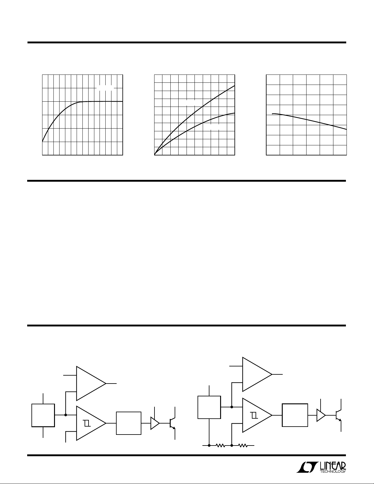
UW
Y
PICA
120
LPER
F
O
R
AT
CCHARA TERIST
E
C
ICS
Quiescent Current vs Temperature Supply Current vs Switch Current Oscillator Frequency
50
V = 3V
IN
40
110
µ
IN
I ( A)
100
90
–25 0 25 50
–50
TEMPERATURE (°C)
U
PI
I
FUUC
(Pin 1): Connect this pin to VIN for normal use. Where
LIM
TI
O
U
S
75
100
LT1173 •TPC06
125
30
20
SUPPLY CURRENT (mA)
10
0
0
V = 5V
200
400 600 800
SWITCH CURRENT (mA)
lower current limit is desired, connect a resistor between
I
and VIN. A 220Ω resistor will limit the switch current
LIM
to approximately 400mA.
V
(Pin 2): Input supply voltage.
IN
SW1 (Pin 3): Collector of power transistor. For step-up
mode connect to inductor/diode. For step-down mode
connect to VIN.
SW2 (Pin 4): Emitter of power transistor. For step-up
mode connect to ground. For step-down mode connect to
inductor/diode. This pin must never be allowed to go more
than a Schottky diode drop below ground.
IN
V = 2V
IN
1000
LT1173 •TPC07
GND (Pin 5): Ground.
AO (Pin 6): Auxiliary Gain Block (GB) output. Open collec-
tor, can sink 100µA.
SET (Pin 7): GB input. GB is an op amp with positive input
connected to SET pin and negative input connected to
1.245V reference.
FB/SENSE (Pin 8): On the LT1173 (adjustable) this pin
goes to the comparator input. On the LT1173-5 and
LT1173-12, this pin goes to the internal application resistor that sets output voltage.
BLOCK
V
IN
1.245V
REFERENCE
GND
4
SET
IDAGRA
A2
GAIN BLOCK/
ERROR AMP
COMPARATOR
FB
LT1173
A1
W
S
AO
OSCILLATOR
I
LIM
DRIVER
SW1
SW2
LT1173 • BD01
REFERENCE
GND
V
IN
1.245V
R1
SET
R2
753k
A2
GAIN BLOCK/
ERROR AMP
Ω
LT1173-5, -12
A1
COMPARATOR
SENSE
LT1173-12:
AO
OSCILLATOR
LT1173-5:
I
DRIVER
R1 = 250k
R1 = 87.4k
LIM
Ω
Ω
SW1
SW2
LT1173 • BD02
Page 5

LT1173 OPER
I
VV
IN
=
−
()
21
10001Ω
AT
LT1173
U
O
I
The LT1173 is a gated oscillator switcher. This type architecture has very low supply current because the switch is
cycled only when the feedback pin voltage drops below the
reference voltage. Circuit operation can best be understood by referring to the LT1173 block diagram. Comparator A1 compares the feedback pin voltage with the 1.245V
reference voltage. When feedback drops below 1.245V, A1
switches on the 24kHz oscillator. The driver amplifier
boosts the signal level to drive the output NPN power
switch. An adaptive base drive circuit senses switch
current and provides just enough base drive to ensure
switch saturation without overdriving the switch, resulting
in higher efficiency. The switch cycling action raises the
output voltage and feedback pin voltage. When the feedback voltage is sufficient to trip A1, the oscillator is gated
off. A small amount of hysteresis built into A1 ensures loop
stability without external frequency compensation. When
the comparator is low the oscillator and all high current
circuitry is turned off, lowering device quiescent current
to just 110µA, for the reference, A1 and A2.
The oscillator is set internally for 23µs ON time and 19µs
OFF time, optimizing the device for circuits where V
and VIN differ by roughly a factor of 2. Examples include a
3V to 5V step-up converter or a 9V to 5V step-down
converter.
OUT
A2 is a versatile gain block that can serve as a low battery
detector, a linear post regulator, or drive an under voltage
lockout circuit. The negative input of A2 is internally
connected to the 1.245V reference. A resistor divider from
VIN to GND, with the mid-point connected to the SET pin
provides the trip voltage in a low battery detector application. The gain block output (AO) can sink 100µA (use a 47k
resistor pull-up to +5V). This line can signal a microcontroller that the battery voltage has dropped below the
preset level.
A resistor connected between the I
maximum switch current. When the switch current exceeds the set value, the switch cycle is prematurely
terminated. If current limit is not used, I
directly to VIN. Propagation delay through the current limit
circuitry is approximately 2µs.
In step-up mode the switch emitter (SW2) is connected to
ground and the switch collector (SW1) drives the inductor; in step-down mode the collector is connected to V
and the emitter drives the inductor.
The LT1173-5 and LT1173-12 are functionally identical to
the LT1173. The -5 and -12 versions have on-chip voltage
setting resistors for fixed 5V or 12V outputs. Pin 8 on the
fixed versions should be connected to the output. No
external resistors are needed.
pin and VIN sets
LIM
should be tied
LIM
IN
U
O
PPLICATI
A
Measuring Input Current at Zero or Light Load
Obtaining meaningful numbers for quiescent current and
efficiency at low output current involves understanding
how the LT1173 operates. At very low or zero load current,
the device is idling for seconds at a time. When the output
voltage falls enough to trip the comparator, the power
switch comes on for a few cycles until the output voltage
rises sufficiently to overcome the comparator hysteresis.
When the power switch is on, inductor current builds up
to hundreds of milliamperes. Ordinary digital multimeters
are not capable of measuring average current because of
bandwidth and dynamic range limitations. A different
S
I FOR ATIO
WU
U
approach is required to measure the 100µA off-state and
500mA on-state currents of the circuit.
Quiescent current can be accurately measured using the
circuit in Figure 1. V
LT1173. The circuit must be “booted” by shorting V2 to
V
. After the LT1173 output voltage has settled, discon-
SET
nect the short. Input voltage is V2, and average input
current can be calculated by this formula:
is set to the input voltage of the
SET
5
Page 6

LT1173
P
F
L
OSC
03
()
It
V
R
e
L
IN
Rt
L
()
=
()
'
–
–'
104
It
V
L
t
L
IN
()
=
()
05
ELi
L
PEAK
=
()
1
2
06
2
U
O
PPLICATI
A
+12V
–
LTC1050
+
V
SET
Figure 1. Test Circuit Measures No Load Quiescent Current of
LT1073 Converter
S
I FOR ATIO
µ1 F*
100
V1 V2
1000 F
*NON-POLARIZED
Ω1M
Ω
+
µ
WU
LT1173
CIRCUIT
LT1173 • TA06
U
Inductor Selection
A DC-DC converter operates by storing energy as magnetic flux in an inductor core, and then switching this
energy into the load. Since it is flux, not charge, that is
stored, the output voltage can be higher, lower, or opposite in polarity to the input voltage by choosing an
appropriate switching topology. To operate as an efficient
energy transfer element, the inductor must fulfill three
requirements. First, the inductance must be low enough
for the inductor to store adequate energy under the worst
case condition of minimum input voltage and switch ON
time. The inductance must also be high enough so that
maximum current ratings of the LT1173 and inductor are
not exceeded at the other worst case condition of maximum input voltage and ON time. Additionally, the inductor
core must be able to store the required flux; i.e., it must not
saturate
. At power levels generally encountered with
LT1173 based designs, small axial leaded units with
saturation current ratings in the 300mA to 1A range
(depending on application) are adequate. Lastly, the inductor must have sufficiently low DC resistance so that
excessive power is not lost as heat in the windings. An
additional consideration is Electro-Magnetic Interference
(EMI). Toroid and pot core type inductors are recommended in applications where EMI must be kept to a
minimum; for example, where there are sensitive analog
circuitry or transducers nearby. Rod core types are a less
expensive choice where EMI is not a problem.
Specifying a proper inductor for an application requires
first establishing minimum and maximum input voltage,
output voltage, and output current. In a step-up converter,
the inductive events add to the input voltage to produce the
output voltage. Power required from the inductor is determined by
PL = (V
+ VD – VIN) (I
OUT
) (02)
OUT
where VD is the diode drop (0.5V for a 1N5818 Schottky).
Energy required by the inductor per cycle must be equal or
greater than
in order for the converter to regulate the output.
When the switch is closed, current in the inductor builds
according to
where R' is the sum of the switch equivalent resistance
(0.8Ω typical at 25°C) and the inductor DC resistance.
When the drop across the switch is small compared to VIN,
the simple lossless equation
can be used. These equations assume that at t = 0,
inductor current is zero. This situation is called “discontinuous mode operation” in switching regulator parlance.
Setting “t” to the switch ON time from the LT1173 specification table (typically 23µs) will yield i
“L” and VIN. Once i
is known, energy in the inductor at
PEAK
for a specific
PEAK
the end of the switch ON time can be calculated as
EL must be greater than PL/F
the required power. For best efficiency i
for the converter to deliver
OSC
should be
PEAK
kept to 1A or less. Higher switch currents will cause
excessive drop across the switch resulting in reduced
efficiency. In general, switch current should be held to as
low a value as possible in order to keep switch, diode and
inductor losses at a minimum.
6
Page 7

LT1173
U
O
PPLICATI
A
As an example, suppose 9V at 50mA is to be generated
from a 3V input. Recalling Equation 02,
PL = (9V + 0.5V – 3V) (50mA) = 325mW. (07)
Energy required from the inductor is
P
F
OSC
Picking an inductor value of 100µH with 0.2Ω DCR results
in a peak switch current of
i
PEAK
Substituting i
EHAJ
Since 19µJ > 13.5µJ the 100µH inductor will work. This
trial-and-error approach can be used to select the optimum inductor. Keep in mind the switch current maximum
rating of 1.5A. If the calculated peak current exceeds this,
consider using the LT1073. The 70% duty cycle of the
LT1073 allows more energy per cycle to be stored in the
inductor, resulting in more output power.
An inductor’s energy storage capability is proportional to
its physical size. If the size of the inductor is too large for
a particular application, considerable size reduction is
possible by using the LT1111. This device is pin compatible with the LT1173 but has a 72kHz oscillator, thereby
reducing inductor and capacitor size requirements by a
factor of three.
For both positive-to-negative (Figure 7) and negative-topositive configurations (Figure 8), all the output power
must be generated by the inductor. In these cases
PL = ( V
In the positive-to-negative case, switch drop can be modeled as a 0.75V voltage source in series with a 0.65Ω
resistor so that
325
L
==
kHz
24
V
3
=
Ω
1
PEAK
1
=
100 0 616 19 0 10
()( )
L
2
+ VD) (I
OUT
S
I FOR ATIO
mW
–µ
emA
–.
1 616 09
into Equation 04 results in
µµ...
J
13 5 08..µ
s
•
123
Ω
100
OUT
H
µ
2
=
). (11)
WU
=
U
()
()
()
In the negative-to-positive case, the switch saturates and
the 0.8Ω switch ON resistance value given for Equation 04
can be used. In both cases inductor design proceeds from
Equation 03.
The step-down case is different than the preceeding three
in that the inductor current flows through the load in a
step-down topology (Figure 6). Current through the switch
should be limited to ~650mA in step-down mode. This can
be accomplished by using the I
in the range of 12V to 25V, a 5V output at 300mA can be
generated with a 220µH inductor and 100Ω resistor in
series with the I
470µH inductor should be used along with the 100Ω
resistor.
Capacitor Selection
Selecting the right output capacitor is almost as important
as selecting the right inductor. A poor choice for a filter
capacitor can result in poor efficiency and/or high output
ripple. Ordinary aluminum electrolytics, while inexpensive
and readily available, may have unacceptably poor equivalent series resistance (ESR) and ESL (inductance). There
are low-ESR aluminum capacitors on the market specifically designed for switch mode DC-DC converters which
work much better than general-purpose units. Tantalum
capacitors provide still better performance at more expense. We recommend OS-CON capacitors from Sanyo
Corporation (San Diego, CA). These units are physically
quite small and have extremely low ESR. To illustrate,
Figures 2, 3, and 4 show the output voltage of an LT1173
based converter with three 100µF capacitors. The peak
switch current is 500mA in all cases. Figure 2 shows a
Sprague 501D, 25V aluminum capacitor. V
over 120mV when the switch turns off, followed by a drop
in voltage as the inductor dumps into the capacitor. This
works out to be an ESR of over 240mΩ. Figure 3 shows the
same circuit, but with a Sprague 150D, 20V tantalum
capacitor replacing the aluminum unit. Output jump is
now about 35mV, corresponding to an ESR of 70mΩ.
Figure 4 shows the circuit with a 16V OS-CON unit. ESR is
now only 20mΩ.
pin. With a 20V to 30V input range, a
LIM
pin. With input voltages
LIM
jumps by
OUT
VL = VIN – 0.75V – IL (0.65Ω). (12)
7
Page 8

LT1173
i
V
L
t
PEA K
IN
ON
=
()
13
PPLICATI
A
50mV/DIV
Figure 2. Aluminum Figure 3. Tantalum Figure 4. OS-CON
5 s/DIV
µ
U
O
S
I FOR ATIO
LT1173 • TA07
WU
50mV/DIV
U
5 s/DIV
In very low power applications where every microampere
is important, leakage current of the capacitor must be
considered. The OS-CON units do have leakage current in
the 5µA to 10µA range. If the load is also in the microampere range, a leaky capacitor will noticeably decrease
efficiency. In this type application tantalum capacitors are
the best choice, with typical leakage currents in the 1µA to
5µA range.
Diode Selection
50mV/DIV
5 s/DIV
µ
LT1173 • TA08
µ
LT1173 • TA09
Step-Up (Boost Mode) Operation
A step-up DC-DC converter delivers an output voltage
higher than the input voltage. Step-up converters are
short circuit protected since there is a DC path from input
to output.
The usual step-up configuration for the LT1173 is shown
in Figure 5. The LT1173 first pulls SW1 low causing VIN –
V
to appear across L1. A current then builds up in L1.
CESAT
At the end of the switch ON time the current in L1 is1:
not
Speed, forward drop, and leakage current are the three
main considerations in selecting a catch diode for LT1173
converters. General purpose rectifiers such as the 1N4001
are
unsuitable
for use in
any
switching regulator applica-
tion. Although they are rated at 1A, the switching time of
a 1N4001 is in the 10µs-50µs range. At best, efficiency will
be severely compromised when these diodes are used; at
worst, the circuit may not work at all. Most LT1173 circuits
will be well served by a 1N5818 Schottky diode. The
combination of 500mV forward drop at 1A current, fast
turn ON and turn OFF time, and 4µA to 10µA leakage
current fit nicely with LT1173 requirements. At peak
switch currents of 100mA or less, a 1N4148 signal diode
may be used. This diode has leakage current in the 1nA5nA range at 25°C and lower cost than a 1N5818. (You can
also use them to get your circuit up and running, but
beware of destroying the diode at 1A switch currents.) In
situations where the load is intermittent and the LT1173 is
idling most of the time, battery life can sometimes be
extended by using a silicon diode such as the 1N4933,
which can handle 1A but has leakage current of less than
1µA. Efficiency will decrease somewhat compared to a
1N5818 while delivering power, but the lower idle current
may be more important.
D1
V
OUT
R2
+
C1
R1
LT1173 • TA10
V
IN
* = OPTIONAL
L1
R3*
V
I
LIM
GND SW2
Figure 5. Step-Up Mode Hookup.
Refer to Table 1 for Component Values
LT1173
IN
SW1
FB
Immediately after switch turn off, the SW1 voltage pin
starts to rise because current cannot instantaneously stop
flowing in L1. When the voltage reaches V
+ VD, the
OUT
inductor current flows through D1 into C1, increasing
V
. This action is repeated as needed by the LT1173 to
OUT
Note 1: This simple expression neglects the effect of switch and coil
resistance. This is taken into account in the “Inductor Selection” section.
8
Page 9

LT1173
PPLICATI
A
U
O
S
I FOR ATIO
WU
U
keep VFB at the internal reference voltage of 1.245V. R1
and R2 set the output voltage according to the formula
V
OUT
=+
1
R
2
() ()
R
1
V
1 245 14..
Step-Down (Buck Mode) Operation
A step-down DC-DC converter converts a higher voltage
to a lower voltage. The usual hookup for an LT1173 based
step-down converter is shown in Figure 6.
V
IN
R3
100
Ω
+
C2
V
I
LIM
Figure 6. Step-Down Mode Hookup
IN
LT1173
GND
SW1
SW2
FB
L1
D1
+
1N5818
C1
V
R2
R1
LT1173 • TA11
OUT
R3 programs switch current limit. This is especially important in applications where the input varies over a wide
range. Without R3, the switch stays on for a fixed time
each cycle. Under certain conditions the current in L1 can
build up to excessive levels, exceeding the switch rating
and/or saturating the inductor. The 100Ω resistor programs the switch to turn off when the current reaches
approximately 800mA. When using the LT1173 in stepdown mode, output voltage should be limited to 6.2V or
less. Higher output voltages can be accommodated by
inserting a 1N5818 diode in series with the SW2 pin
(anode connected to SW2).
Inverting Configurations
The LT1173 can be configured as a positive-to-negative
converter (Figure 7), or a negative-to-positive converter
(Figure 8). In Figure 7, the arrangement is very similar to
a step-down, except that the high side of the feedback is
referred to ground. This level shifts the output negative.
As in the step-down mode, D1 must be a Schottky
diode, and V
should be less than 6.2V. More nega-
OUT
tive output voltages can be accomodated as in the prior
section.
When the switch turns on, SW2 pulls up to V
puts a voltage across L1 equal to VIN – VSW – V
– VSW. This
IN
OUT
,
causing a current to build up in L1. At the end of the switch
ON time, the current in L1 is equal to
V
VV
−−
IN
i
PEAK
=
SW OUT
L
t
.15
ON
()
When the switch turns off, the SW2 pin falls rapidly and
actually goes below ground. D1 turns on when SW2
reaches 0.4V below ground.
DIODE
. The voltage at SW2 must never be allowed to go
D1 MUST BE A SCHOTTKY
below –0.5V. A silicon diode such as the 1N4933 will allow
SW2 to go to – 0.8V, causing potentially destructive power
dissipation inside the LT1173. Output voltage is determined by
V
OUT
=+
1
R
2
() ()
R
1
V
1 245 16..
+V
IN
R3
R1
R2
LT1173 • F07
+
C2
–V
OUT
V
I
LIM
Figure 7. Positive-to-Negative Converter
IN
LT1173
GND
SW1
SW2
FB
L1
D1
1N5818
+
C1
In Figure 8, the input is negative while the output is
positive. In this configuration, the magnitude of the input
voltage can be higher or lower than the output voltage. A
level shift, provided by the PNP transistor, supplies proper
polarity feedback information to the regulator.
9
Page 10

LT1173
PPLICATI
A
+
C2
–V
IN
Using the I
U
O
S
I FOR ATIO
L1
V
I
LIM
AO
GND SW2
Figure 8. Negative-to-Positive Converter
Pin
LIM
IN
SW1
LT1173
FB
WU
D1
+
C1
R2
R1
V = 1.245V + 0.6V
( )
OUT
R2
U
+V
OUT
R1
2N3906
LT1173 • TA13
The LT1173 switch can be programmed to turn off at a set
switch current, a feature not found on competing devices.
This enables the input to vary over a wide range without
exceeding the maximum switch rating or saturating the
inductor. Consider the case where analysis shows the
LT1173 must operate at an 800mA peak switch current
with a 2.0V input. If VIN rises to 4V, the peak switch current
will rise to 1.6A, exceeding the maximum switch current
rating. With the proper resistor selected (see the “Maximum Switch Current vs R
” characteristic), the switch
LIM
current will be limited to 800mA, even if the input voltage
increases.
Another situation where the I
feature is useful occurs
LIM
when the device goes into continuous mode operation.
This occurs in step-up mode when
V
+
OUT DIODE
V
VV DC
−
IN SW
1
<
−
1
17.
()
When the input and output voltages satisfy this relationship, inductor current does not go to zero during the
switch OFF time. When the switch turns on again, the
current ramp starts from the non-zero current level in the
inductor just prior to switch turn on. As shown in Figure
9, the inductor current increases to a high level before the
comparator turns off the oscillator. This high current can
cause excessive output ripple and requires oversizing the
output capacitor and inductor. With the I
feature,
LIM
however, the switch current turns off at a programmed
level as shown in Figure 10, keeping output ripple to a
minimum.
I
L
ON
SWITCH
OFF
Figure 9. No Current Limit Causes Large Inductor
Current Build-Up
PROGRAMMED CURRENT LIMIT
I
L
ON
SWITCH
OFF
Figure 10. Current Limit Keeps Inductor Current Under Control
LT1173 • TA14
LT1173 • TA15
Figure 11 details current limit circuitry. Sense transistor
Q1, whose base and emitter are paralleled with power
switch Q2, is ratioed such that approximately 0.5% of Q2’s
collector current flows in Q1’s collector. This current is
passed through internal 80Ω resistor R1 and out through
the I
between I
pin. The value of the external resistor connected
LIM
and VIN sets the current limit. When suffi-
LIM
cient switch current flows to develop a VBE across R1 +
R
, Q3 turns on and injects current into the oscillator,
LIM
turning off the switch. Delay through this circuitry is
approximately 2µs. The current trip point becomes less
accurate for switch ON times less than 4µs. Resistor
values programming switch ON time for 2µs or less will
cause spurious response in the switch circuitry although
the device will still maintain output regulation.
R
LIM
V
IN
Q3
OSCILLATOR
Figure 11. LT1173 Current Limit Circuitry
(EXTERNAL)
DRIVER
I
LIM
R1
80Ω
(INTERNAL)
Q1
SW1
Q2
SW2
LT1173 • TA28
10
Page 11

LT1173
PPLICATI
A
U
O
S
I FOR ATIO
WU
U
Using the Gain Block
The gain block (GB) on the LT1173 can be used as an error
amplifier, low battery detector or linear post regulator. The
gain block itself is a very simple PNP input op amp with an
open collector NPN output. The negative input of the gain
block is tied internally to the 1.245V reference. The positive input comes out on the SET pin.
Arrangement of the gain block as a low battery detector is
straightforward. Figure 12 shows hookup. R1 and R2 need
only be low enough in value so that the bias current of the
SET input does not cause large errors. 100kΩ for R2 is
adequate. R3 can be added to introduce a small amount of
hysteresis. This will cause the gain block to “snap” when
the trip point is reached. Values in the 1M-10M range are
optimal. The addition of R3 will change the trip point,
however.
V
IN
–
+
LT1173
GND
R3
V
– 1.245V
LB
R1 =
11.7µA
= BATTERY TRIP POINT
V
LB
R2 = 100kΩ
R3 = 4.7MΩ
AO
R1
1.245V
V
BAT
R2
REF
SET
Figure 12. Setting Low Battery Detector Trip Point
+5V
100k
TO
PROCESSOR
LT1173 • TA16
Table 1. Component Selection for Common Converters
INPUT OUTPUT OUTPUT CIRCUIT INDUCTOR INDUCTOR CAPACITOR
VOLTAGE VOLTAGE CURRENT (MIN) FIGURE VALUE PART NUMBER VALUE NOTES
2.0-3.1 5 90mA 5 47µH G GA10-472K, C CTX50-1 100µF*
2.0-3.1 5 10mA 5 220µH G GA10-223K, C CTX 22µF
2.0-3.1 12 50mA 5 47µH G GA10-472K, C CTX50-1 47µF*
2.0-3.1 12 10mA 5 150µH G GA10-153K 22µF
5 12 90mA 5 120µH G GA10-123K 100µF
5 12 30mA 5 150µH G GA10-153K 47µF**
5 15 50mA 5 120µH G GA10-123K C CTX100-4 47µF
5 30 25mA 5 100µH G GA10-103K, C CTX100-4 10µF, 50V
6.5-9.5 5 50mA 6 47µH G GA10-472K, C CTX50-1 100µF**
12-20 5 300mA 6 220µH G GA20-223K 220µF**
20-30 5 300mA 6 470µH G GA20-473K 470µF**
5 –5 75mA 7 100µH G GA10-103K, C CTX100-4 100µF**
12 –5 250mA 7 470µH G GA40-473K 220µF**
–5 5 150mA 8 100µH G GA10-103K, C CTX100-4 220µF
–5 12 75mA 8 100µH G GA10-103K, C CTX100-4 47µF
G = Gowanda
C = Coiltronics
* Add 68Ω from I
** Add 100Ω from I
LIM
to V
LIM
IN
to V
IN
11
Page 12

LT1173
PPLICATI
A
U
O
S
I FOR ATIO
WU
U
Table 2. Inductor Manufacturers
MANUFACTURER PART NUMBERS
Gowanda Electronics Corporation GA10 Series
1 Industrial Place GA40 Series
Gowanda, NY 14070
716-532-2234
Caddell-Burns 7300 Series
258 East Second Street 6860 Series
Mineola, NY 11501
516-746-2310
Coiltronics International Custom Toroids
984 S.W. 13th Court Surface Mount
Pompano Beach, FL 33069
305-781-8900
Renco Electronics Incorporated RL1283
60 Jefryn Boulevard, East RL1284
Deer Park, NY 11729
800-645-5828
Table 3. Capacitor Manufacturers
MANUFACTURER PART NUMBERS
Sanyo Video Components OS-CON Series
2001 Sanyo Avenue
San Diego, CA 92173
619-661-6835
Nichicon America Corporation PL Series
927 East State Parkway
Schaumberg, IL 60173
708-843-7500
Sprague Electric Company 150D Solid Tantalums
Lower Main Street 550D Tantalex
Sanford, ME 04073
207-324-4140
U
O
PPLICATITYPICAL
SA
3V to –22V LCD Bias Generator
R1
100Ω
LT1173
V
SW2
IN
SW1
FB
I
LIM
2 X 1.5V
CELLS
* L1 = GOWANDA GA10-103K
COILTRONICS CTX100-4
FOR 5V INPUT CHANGE R1 TO 47Ω.
CONVERTER WILL DELIVER –22V AT 40mA.
3V
GND
L1*
100µH
1N5818
1N4148
2.21M
1%
+
4.7µF
1N5818
118k
1%
22µF+220k
0.1µF
–22V OUTPUT
7mA AT 2.0V INPUT
70% EFFICIENCY
LT1173 • TA19
12
Page 13

PPLICATITYPICAL
3V to 5V Step-Up Converter
L1*
µ
100 H
I
2 X 1.5V
CELLS
GND
* L1 = GOWANDA GA10-103K
COILTRONICS CTX100-1 (SURFACE MOUNT)
+VIN
5V INPUT
V
LIM
IN
SW1
LT1173-5
SENSE
SW2
+5V to –5V Converter +20V to 5V Step-Down Converter
100
Ω
O
+
U
SA
1N5818
100 Fµ
5V OUTPUT
150mA AT 3V INPUT
60mA AT 2V INPUT
LT1173 • TA17
9V to 5V Step-Down Converter
100
Ω
V
LT1173-5
100
IN
SW1
SENSE
SW2
Ω
47µH
1N5818
L1*
+
I
LIM
9V
BATTERY
GND
* L1 = GOWANDA GA10-472K
COILTRONICS CTX50-1
FOR HIGHER OUTPUT CURRENTS SEE LT1073 DATASHEET
+VIN
12V-28V
100 Fµ
LT1173
5V OUTPUT
150mA AT 9V INPUT
50mA AT 6.5V INPUT
LT1173 • TA18
+
22µF
* L1 = GOWANDA GA10-103K
COILTRONICS CTX100-1
44mH
48V DC
44mH
*L1 = CTX110077
I
= 120µA
Q
I
LIM
LT1173-5
GND
1N5818
~
~
V
IN
SW1
SENSE
SW2
+
–
100µH
+
L1*
100 F
47µF
100V
µ
10nF
1N965B
+
–5V OUTPUT
75mA
LT1173 • TA20
3.6MΩ
10k
15V
Telecom Supply
VN2222
12V
I
LIM
+
10µF
16V
GND
I
LIM
GND
* L1 = GOWANDA GA20-223K
L1*
500µH
100Ω
V
IN
SW1
LT1173
FB
SW2
LT1173-5
1N4148
V
IN
SW1
SENSE
SW2
IRF530
220µH
1N5818
MUR110
220µF
10V
L1*
5V OUTPUT
300mA
+
100 Fµ
LT1173 • TA21
+5V
+
100mA
390kΩ
2N5400
110kΩ
LT1173 • TA22
13
Page 14

LT1173
PPLICATITYPICAL
4 X NICAD
OR
ALKALINE
CELLS
*L1 = COILTRONICS CTX100-4
GOWANDA GA20-103K
470µF
U
O
SA
“5 to 5” Step-Up or Step-Down Converter
L1*
100µH
56Ω
I
LIM
+
7
SET AO
GND
5
V
IN
V
OUT
21
V
IN
SW1
LT1173
FB
SW2
4
= 2.6V TO 7.2V
= 5V AT 100mA
3
6
8
1N5818
SI9405DY
470k 75k
+5V
OUTPUT
+
470µF
+
470µF
240Ω
24k
LT1173 • TA23
47k
2N3906
2 X NICAD
100k 100k
*L1 = COILTRONICS CTX-20-5-52
†
1% METAL FILM
2V to 5V at 300mA Step-Up Converter with Under Voltage Lockout
100k
100k
2.2M
AO
SET
I
LIM
GND
L1*
20µH, 5A
V
IN
100
SW1 2N4403
LT1173
FB
SW2
301k
†
220
†
5Ω
47Ω
1N5820
MJE200
+
+5V OUTPUT
300mA
LOCKOUT AT
1.85V INPUT
100µF
OS-CON
LT1173 • TA24
14
Page 15

LT1173
U
O
PPLICATITYPICAL
V
IN
5V-12V
SA
Voltage Controlled Positive-to-Negative Converter
V
GND
IN
LT1173
0.22
I
LIM
SW2
1N5818
SW1
FB
150
MJE210
220
V
IN
LT1006
200k
–
+
L1*
50µH, 2.5A
1N5820
39k
+
100µF
–V
2W MAXIMUM OUTPUT
V
C
= –5.13 • VC
OUT
(0V TO 5V)
* L1 = GOWANDA GT10-101
0.22Ω
V
IN
7V-24V
V
IN
LT1173
GND
OPERATE STANDBY
High Power, Low Quiescent Current Step-Down Converter
L1*
1N5820
121k
≤ 150µA
Q
25µH, 2A
+
I
LIM
SW2
1N5818
SW1
FB
100Ω
1/2W
18V
1W
2k
MTM20P08
51Ω
2N3904
1N4148
40.2k
* L1 = GOWANDA GT10-100
EFFICIENCY ≥ 80% FOR 10mA ≤ I
STANDBY I
2 Cell Powered Neon Light Flasher
0.02µF
470µF
LOAD
LT1173 • TA25
5V
500mA
≤ 500mA
LT1173 • TA26
3V
*TOKO 262LYF-0100K
L1*
470µH
I
LIM
GND
V
IN
SW1
LT1173
FB
SW2
Information furnished by Linear Technology Corporation is believed to be accurate and reliable.
However, no responsibility is assumed for its use. Linear Technology Corporation makes no representation that the interconnection of its circuits as described herein will not infringe on existing patent rights.
1N4148
0.02µF
1.3M
1N4148
100M
1N4148
95V REGULATED
0.02µF
0.68µF
3.3M
200V
NE-2
BLINKS AT
0.5Hz
LT1173 • TA27
15
Page 16

LT1173
PACKAGEDESCRIPTI
U
O
Dimensions in inches (milimeters) unless otherwise noted.
N8 Package
8-Lead Plastic DIP
0.400*
(10.160)
MAX
876
5
0.255 ± 0.015*
(6.477 ± 0.381)
0.300 – 0.325
(7.620 – 8.255)
0.065
(1.651)
0.009 – 0.015
(0.229 – 0.381)
+0.025
0.325
–0.015
+0.635
8.255
()
–0.381
*THESE DIMENSIONS DO NOT INCLUDE MOLD FLASH OR PROTRUSIONS.
MOLD FLASH OR PROTURSIONS SHALL NOT EXCEED 0.010 INCH (0.254mm).
TYP
0.045 ± 0.015
(1.143 ± 0.381)
1234
0.045 – 0.065
(1.143 – 1.651)
0.100 ± 0.010
(2.540 ± 0.254)
S8 Package
8-Lead Plastic SOIC
0.189 – 0.197*
(4.801 – 5.004)
8
7
0.018 ± 0.003
(0.457 ± 0.076)
5
6
0.130 ± 0.005
(3.302 ± 0.127)
0.125
(3.175)
MIN
(0.380)
0.015
MIN
N8 0694
16
0.010 – 0.020
(0.254 – 0.508)
0.008 – 0.010
(0.203 – 0.254)
*THESE DIMENSIONS DO NOT INCLUDE MOLD FLASH OR PROTRUSIONS.
MOLD FLASH OR PROTRUSIONS SHALL NOT EXCEED 0.006 INCH (0.15mm).
× 45°
0°– 8° TYP
0.016 – 0.050
0.406 – 1.270
Linear Technology Corporation
1630 McCarthy Blvd., Milpitas, CA 95035-7487
(408) 432-1900
●
FAX
: (408) 434-0507
●
TELEX
: 499-3977
0.228 – 0.244
(5.791 – 6.197)
0.053 – 0.069
(1.346 – 1.752)
0.014 – 0.019
(0.355 – 0.483)
0.150 – 0.157*
(3.810 – 3.988)
1
3
2
4
0.004 – 0.010
(0.101 – 0.254)
0.050
(1.270)
BSC
SO8 0294
LT/GP 0894 2K REV B • PRINTED IN USA
LINEAR TECHNOLOGY CORPORATION 1994
 Loading...