

Datasheet LT1009CH, LT1009S8, LT1009IZ, LT1009IS8, LT1009CZ Datasheet (Linear Technology)
...Page 1
FEATURES
LT1009 Series
2.5V Reference
U
DESCRIPTIO
■
Maximum Initial Tolerance: 0.2%
■
Guaranteed
■
Maximum 0.6Ω Dynamic Impedance
■
Wide Operating Current Range
■
Directly Interchangeable with LM136 for Improved
Temperature Stability
Performance
■
No Adjustments Needed for Minimum Temperature
Coefficient
U
APPLICATIO S
■
Reference for 5V Systems
■
8-Bit A/D and D/A Reference
■
Digital Voltmeters
■
Current Loop Measurement and Control Systems
■
Power Supply Monitor
U
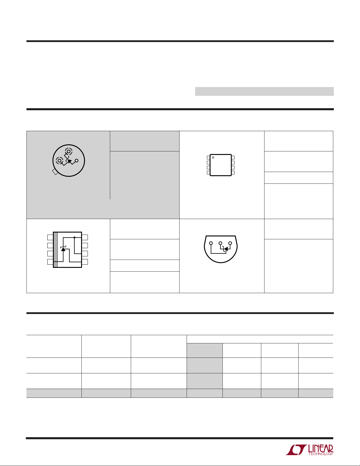
TYPICAL APPLICATION
The LT®1009 is a precision trimmed 2.5V shunt regulator
diode featuring a maximum initial tolerance of only ±5mV.
The low dynamic impedance and wide operating current
range enhances its versatility. The 0.2% reference tolerance is achieved by on-chip trimming which not only
minimizes the initial voltage tolerance but also minimizes
the temperature drift.
Even though no adjustments are needed with the LT1009,
a third terminal allows the reference voltage to be adjusted
±5% to calibrate out system errors. In many applications,
the LT1009 can be used as a pin-to-pin replacement of the
LM136 and the external trim network eliminated.
For a lower drift 2.5V reference, see the LT1019 data sheet.
, LTC and LT are registered trademarks of Linear Technology Corporation.
2.5V Reference
5V TO 35V
3.6k
LT1009
*DOES NOT AFFECT
TEMPERATURE COEFFICIENT.
±5% TRIM RANGE
10k*
TRIM
OUTPUT
1009 TA01
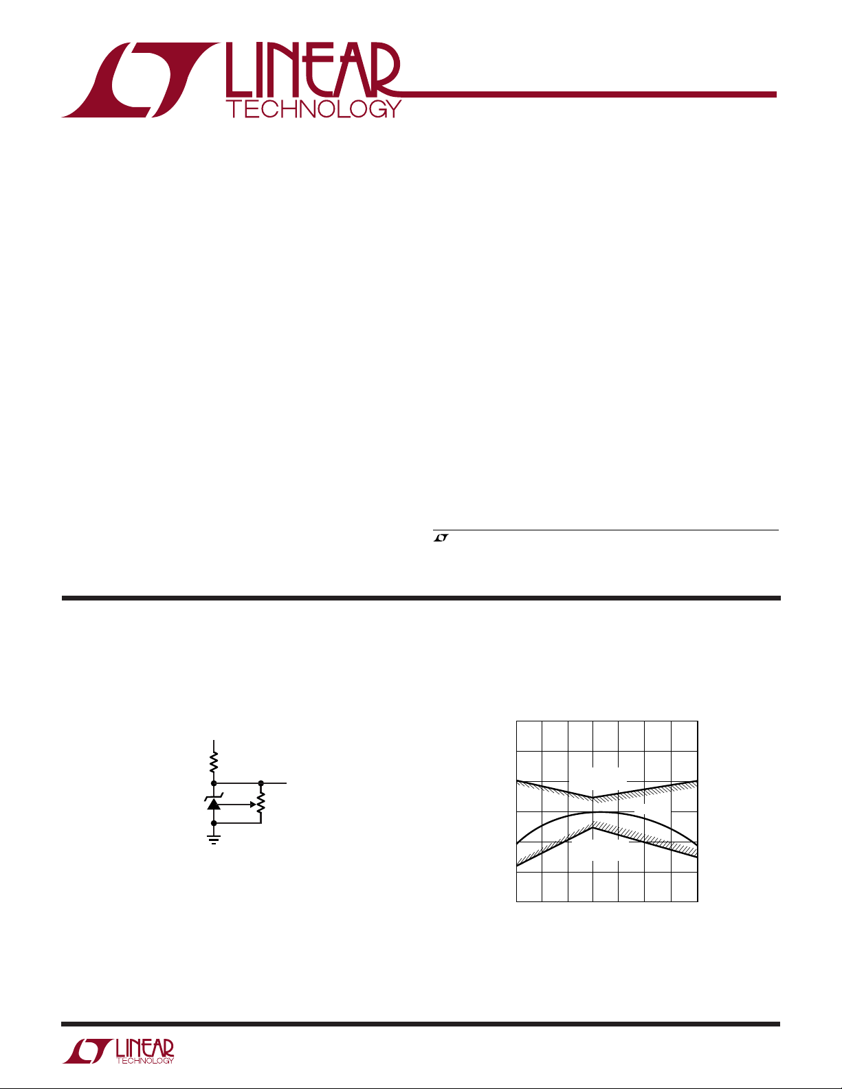
Output Voltage
2.53
2.52
–25 0
GUARANTEED
MAXIMUM
GUARANTEED
TEMPERATURE (°C)
2.51
2.50
2.49
REFERENCE VOLTAGE (V)
2.48
2.47
–50
MINIMUM
50 100 125
25 75
TYPICAL
1009 TA02
1
Page 2
LT1009 Series
WWWU
ABSOLUTE AXI U RATI GS
(Note 1)
Reverse Current.................................................... 20mA
Forward Current ................................................... 10mA
Storage Temperature Range ................. –65°C to 150°C
Lead Temperature (Soldering, 10 sec).................. 300°C
UU
W
PACKAGE/ORDER I FOR ATIO
BOTTOM VIEW
+
ADJ
–
H PACKAGE
3-LEAD TO-46 METAL CAN
T
= 150°C, θJA = 440°C/ W, θJC = 80°C/W
JMAX
OBSOLETE PACKAGE
Consider the MS8, S8 or Z Packages for Alternate Source
TOP VIEW
1
NC
NC
2
NC
3
(–)
4
S8 PACKAGE
8-LEAD PLASTIC SO
T
= 150°C, θJA = 190°C/W
JMAX
8
(+)
7
NC
6
(+)
5
ADJ
ORDER PART
NUMBER
LT1009MH
LT1009CH
ORDER PART
NUMBER
LT1009S8
LT1009IS8
S8 PART MARKING
1009
1009I
Operating Temperature Range
LT1009/LT1009C .................................. 0°C to 70°C
LT1009I........................................... – 40°C to 85°C
LT1009M (OBSOLETE)................... –55°C to 125°C
ORDER PART
TOP VIEW
NC
1
NC
2
NC
3
(–)
4
MS8 PACKAGE
8-LEAD PLASTIC MSOP
T
= 150°C, θJA = 250°C/W
JMAX
BOTTOM VIEW
+
ADJ
8
(+)
7
NC
6
(+)
5
ADJ
–
NUMBER
LT1009CMS8
MS8 PART MARKING
LTQZ
ORDER PART
NUMBER
LT1009CZ
LT1009IZ
Z PACKAGE
3-LEAD PLASTIC TO-92
T
= 100°C, θJA = 160°C/ W
JMAX
Consult LTC Marketing for parts specified with wider operating temperature ranges.
U
AVAILABLE OPTIO S
TEMPERATURE
ACCURACY COEFFICIENT
TEMPERATURE
0°C to 70°C 0.20 25 LT1009CH LT1009CZ
–40°C to 85°C 0.20 35 LT1009IZ
–55°C to 125°C 0.20 35 LT1009MH
(%) (ppm/°C) OBSOLETE (MS8) (S8) (Z)
0.40 25 LT1009CMS8 LT1009S8
0.40 35 LT1009IS8
PACKAGE STYLE
TO-46 (H) MSOP-8 SO-8 TO-92
2
Page 3
LT1009 Series
ELECTRICAL CHARACTERISTICS
The ● denotes specifications which apply over the full operating temperature range, otherwise specifications are TA = 25°C.
LT1009M LT1009I LT1009/LT1009C
SYMBOL PARAMETER CONDITIONS MIN TYP MAX MIN TYP MAX MIN TYP MAX UNITS
V
Z
∆V
∆I
r
Z
∆V
∆Temp Coefficient (Notes 2, 3) – 40°C ≤ T
∆V
∆Time
Reverse Breakdown TA = 25°C, IR = 1mA, H, Z Pkg 2.495 2.500 2.505 2.495 2.500 2.505 2.495 2.500 2.505 V
Voltage MS, S Pkg 2.49 2.50 2.51 2.49 2.50 2.51 V
Reverse Breakdown 400µA ≤ IR ≤ 10mA 2.6 6 2.6 10 2.6 10 mV
Z
Change with Current ● 3.0 10 3.0 12 3.0 12 mV
R
Reverse Dynamic IR = 1mA 0.2 0.6 0.2 1.0 0.2 1.0 Ω
Impedance
Temperature Stability T
Average Temperature 0°C ≤ TA ≤ 70°C 15 25 15 25 15 25 ppm/°C
Z
Long-Term Stability TA = 25°C ±0.1°C, IR = 1mA 20 20 20 ppm/kHr
Z
≤ TA ≤ T
MIN
–55°C ≤ T
MAX
≤ 85°C 35 ppm/°C
A
≤ 125°C 25 35 ppm/°C
A
● 0.4 1.0 0.4 1.4 0.4 1.4 Ω
● 15 15 1.8 4 mV
Note 1: Absolute Maximum Ratings are those values beyond which the life
of a device may be impaired.
Note 3: Average temperature coefficient is defined as the total voltage
change divided by the specified temperature change.
Note 2: Guaranteed by Design.
UW
TYPICAL PERFOR A CE CHARACTERISTICS
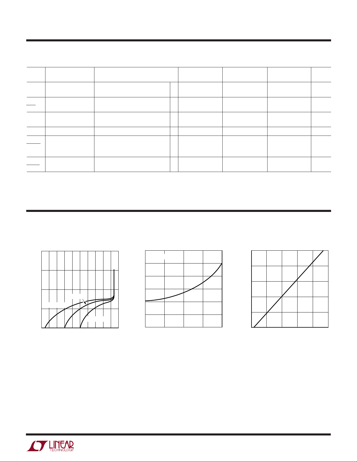
Reverse Characteristics
–1
10
–2
10
–3
10
TJ = 25°C
TJ = 125°C
–4
REVERSE CURRENT (A)
10
–5
10
0.5
1.0
REVERSE VOLTAGE (V)
1.4
TJ = –55°C
1.8
2.2
2.6
1009 G01
Forward Characteristics
1.2
TJ = 25°C
1.0
0.8
0.6
0.4
FORWARD VOLTAGE (V)
0.2
0
0.001
0.01 0.1 1 10
FORWARD CURRENT (mA)
1009 G02
Reverse Voltage Change
5
4
3
2
1
REVERSE VOLTAGE CHANGE (mV)
0
4
0
8
REVERSE CURRENT (mA)
12
16
20
1009 G03
3
Page 4

LT1009 Series
UW
TYPICAL PERFOR A CE CHARACTERISTICS
Dynamic Impedance Output Noise Voltage
100
IR = 1mA
–55°C ≤ T
10
1
DYNAMIC IMPEDANCE (Ω)
0.1
10
≤ 125°C
J
100 1k 10k 100k
FREQUENCY (Hz)
1009 G04
250
200
150
NOISE (pV/√Hz)
100
50
10 100k
WW
SCHE ATIC DIAGRA
100
FREQUENCY (Hz)
Q7
Response Time
IR = 1mA
T
= 25°C
J
1k
10k
1009 G05
3.5
3.0
2.5
2.0
1.5
1.0
0.5
0
VOLTAGE SWING (V)
10
4
0
0
INPUT
OUTPUT
5k
INPUT
1
TIME (µs)
OUTPUT
20
1009 G06
+
Q11
24k
Q8
Q7
20pF
10k
Q2
Q1
Q3
Q4
Q5
30pF
Q10
Q9
Q6
Q12
720Ω
24k
Q13
6.6k
500Ω
6.6k
30k
1009 SD
ADJ
–
4
Page 5

TYPICAL APPLICATIO S
Wide Supply Range, Adjustable Reference Low Temperature Coefficient Power Regulator
LT1009 Series
U
3.6V TO 40V
+
V
–
V
LT1009
LM334
IN
LT317A
IN OUT
ADJ
LT1009
1.2k
V
R
62Ω
10k
1009 TA03
375Ω
2k
V
OUT
1009 TA04
Switchable ±1.25V Bipolar Reference
5V
5k
5V
–5V
5k
LT1009
10k
1%
OUT
9.76k
1%
–5V
500Ω
1009 TA05
5k
5
Page 6

LT1009 Series
PACKAGE DESCRIPTIO
0.209 – 0.219
(5.309 – 5.537)
0.178 – 0.195
(4.521 – 4.953)
0.500
(12.700)
REFERENCE
PLANE
MIN
0.016 – 0.021**
(0.406 – 0.533)
DIA
**
U
H Package
2-Lead and 3-Lead TO-46 Metal Can
(LTC DWG # 05-08-1340)
0.085 – 0.105
(2.159 – 2.667)
*
0.025
(0.635)
MAX
*
LEAD DIAMETER IS UNCONTROLLED BETWEEN THE REFERENCE PLANE
AND 0.045" BELOW THE REFERENCE PLANE
FOR SOLDER DIP LEAD FINISH, LEAD DIAMETER IS
(1.270)
0.036 – 0.046
(0.914 – 1.168)
0.050
TYP
0.100
(2.540)
TYP
PIN 1
45°
0.016 – 0.024
(0.406 – 0.610)
0.050
(1.270)
TYP
FOR 3-LEAD PACKAGE ONLY
0.028 – 0.048
(0.711 – 1.219)
H02/03(TO-46) 1098
OBSOLETE PACKAGE
MS8 Package
8-Lead Plastic MSOP
(Reference LTC DWG # 05-08-1660)
0.118 ± 0.004*
(3.00 ± 0.102)
0.193 ± 0.006
(4.90 ± 0.15)
0.007
(0.18)
0.021
± 0.006
(0.53 ± 0.015)
* DIMENSION DOES NOT INCLUDE MOLD FLASH, PROTRUSIONS OR GATE BURRS. MOLD FLASH,
PROTRUSIONS OR GATE BURRS SHALL NOT EXCEED 0.006" (0.152mm) PER SIDE
** DIMENSION DOES NOT INCLUDE INTERLEAD FLASH OR PROTRUSIONS.
INTERLEAD FLASH OR PROTRUSIONS SHALL NOT EXCEED 0.006" (0.152mm) PER SIDE
° – 6° TYP
0
SEATING
PLANE
0.009 – 0.015
(0.22 – 0.38)
0.043
(1.10)
MAX
8
12
0.0256
(0.65)
BSC
7
6
5
4
3
0.118 ± 0.004**
(3.00 ± 0.102)
0.034
(0.86)
REF
0.005
± 0.002
(0.13 ± 0.05)
MSOP (MS8) 1100
6
Page 7

PACKAGE DESCRIPTIO
U
S8 Package
8-Lead Plastic Small Outline (Narrow .150 Inch)
(Reference LTC DWG # 05-08-1610)
0.189 – 0.197*
(4.801 – 5.004)
7
8
6
LT1009 Series
5
0.060 ± 0.005
(1.524± 0.127)
DIA
0.180 ± 0.005
(4.572 ± 0.127)
0.228 – 0.244
(5.791 – 6.197)
0.010 – 0.020
(0.254 – 0.508)
0.008 – 0.010
(0.203 – 0.254)
*
DIMENSION DOES NOT INCLUDE MOLD FLASH. MOLD FLASH
SHALL NOT EXCEED 0.006" (0.152mm) PER SIDE
**
DIMENSION DOES NOT INCLUDE INTERLEAD FLASH. INTERLEAD
FLASH SHALL NOT EXCEED 0.010" (0.254mm) PER SIDE
× 45°
0°– 8° TYP
0.016 – 0.050
(0.406 – 1.270)
Z Package
3-Lead Plastic TO-92 (Similar to TO-226)
(Reference LTC DWG # 05-08-1410)
0.180 ± 0.005
(4.572 ± 0.127)
0.90
(2.286)
NOM
0.053 – 0.069
(1.346 – 1.752)
0.014 – 0.019
(0.355 – 0.483)
TYP
0.150 – 0.157**
(3.810 – 3.988)
1
3
2
4
0.004 – 0.010
(0.101 – 0.254)
0.050
(1.270)
BSC
SO8 1298
0.500
(12.70)
MIN
5°
0.050
UNCONTROLLED
LEAD DIMENSION
(1.270)
MAX
0.016 ± 0.003
0.050
(1.27)
BSC
321
Information furnished by Linear Technology Corporation is believed to be accurate and reliable.
However, no responsibility is assumed for its use. Linear Technology Corporation makes no representation that the interconnection of its circuits as described herein will not infringe on existing patent rights.
(0.406 ± 0.076)
0.060 ± 0.010
(1.524 ± 0.254)
0.140 ± 0.010
(3.556 ± 0.127)
10° NOM
NOM
0.015 ± 0.002
(0.381 ± 0.051)
0.098 +016/–0.04
(2.5 +0.4/–0.1)
2 PLCS
REFER TO TAPE AND REEL SECTION OF
LTC DATA BOOK FOR ADDITIONAL INFORMATION
Z3 (TO-92) 0401
TO-92 TAPE AND REEL
7
Page 8

LT1009 Series
TYPICAL APPLICATIO
U
Low Noise 2.5V Buffered Reference
V
≥ 6V
IN
1µF
10k
1k
LT1009
100k
2
1k10k
3
+
20µF
+
20µF
–
LT1001C
+
7
6
2.5V
4
1009 TA06
RELATED PARTS
PART NUMBER DESCRIPTION COMMENTS
LT1019 Precision Series Reference Bandgap, 0.05%, 5ppm/°C
LT1236 Precision Series Reference 5V and 10V Zener-Based 5ppm/°C, SO-8 Package
LTC®1798 Micropower Low Dropout Series Reference 0.15% Max, 6.5µA Supply Current
LT1460 Micropower Precision Series Reference Bandgap, 130µA Supply Current 10ppm/°C, Available in SOT-23
LT1634 Micropower Precision Shunt Voltage Reference Bandgap 0.05%, 10ppm/°C, 10µA Supply Current
LT1461 Micropower Precision Series Reference 0.04% Max, 3ppm/°C Max, 35µA Supply Current
8
Linear Technology Corporation
1630 McCarthy Blvd., Milpitas, CA 95035-7417
(408) 432-1900 ● FAX: (408) 434-0507
●
www.linear-tech.com
1009fc LT/TP 0501 1.5K REV C • PRINTED IN USA
LINEAR TECHNOLOGY CORPORATION 1985
 Loading...