

Datasheet LSYA676-Q+R, LSYA676-Q+Q, LSYA676-P+R, LSYA676, LSYA676-P+Q Datasheet (Siemens)
...Page 1
Semiconductor Group 1 11.96
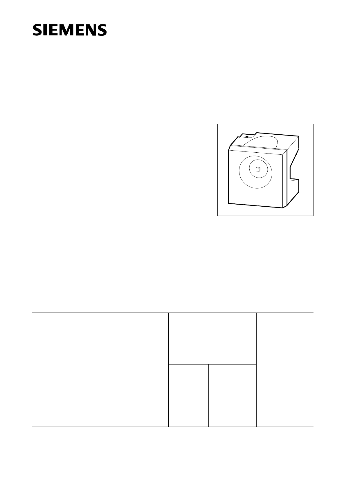
Hyper Multi SIDELED
®
Hyper-Bright LED
LSY A676
Besondere Merkmale
● Gehäusefarbe: weiß
● als optischer Indikator einsetzbar
● zur Hintergrundbeleuchtung, Lichtleiter- und Linsenein-
kopplung
● hohe Signalwirkung durch Farbwechsel der LED möglich
● bei geeigneter Ansteuerung, Farbwechsel von grün über
gelb und orange bis super-rot möglich
● für alle SMT-Bestück- und Löttechniken geeignet
● gegurtet (12-mm-Filmgurt)
Features
● color of package: white
● for use as optical indicator
● for backlighting, optical coupling into light pipes and lenses
● high signal efficiency possible by color change of the LED
● with appropriate controlling it is possible to change color
from green to yellow and orange to super-red
● suitable for all SMT assembly and soldering methods
● available taped on reel (12 mm tape)
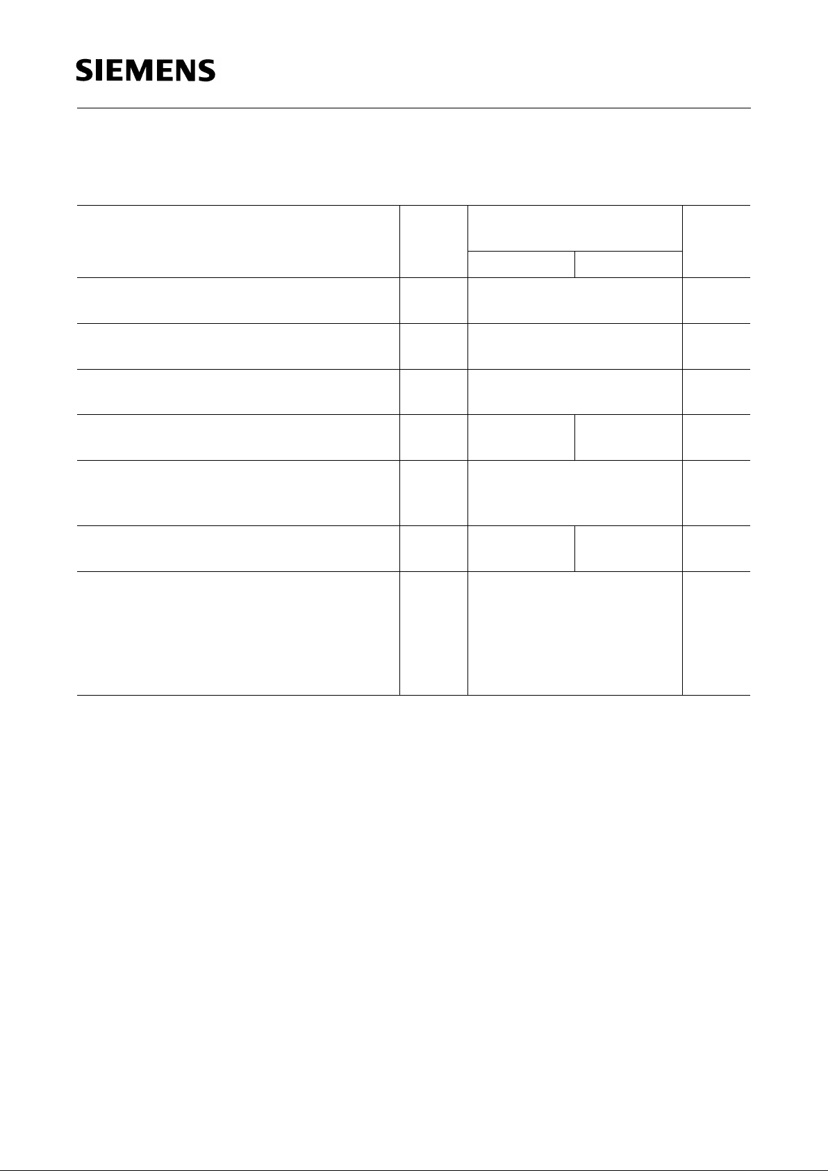
Typ
Type
Emissionsfarbe
Color of
Emission
Farbe der
Lichtaustrittsfläche
Color of the
Light
Emitting
Area
Lichtstärke
Luminous Intensity
I
F
= 20 mA
I
V
(mcd)
Bestellnummer
Ordering Code
super-red yellow
LSY A676
LSY A676-P+P
LSY A676-P+Q
LSY A676-P+R
LSY A676-Q+Q
LSY A676-Q+R
super-red /
yellow
colorless
clear
≥ 40
40... 80
40... 80
40... 80
63...125
63...125
≥ 40
40... 80
63... 125
100...200
63... 125
100...200
Q62703-Q3374
vpl06880
Page 2
Semiconductor Group 2
LSY A676
Grenzwerte
Maximum Ratings
Bezeichnung
Parameter
Symbol
Symbol
Wert
Value
Einheit
Unit
SY
Betriebstemperatur
Operating temperature range
T
op
– 55 ... + 100 ˚C
Lagertemperatur
Storage temperature range
T
stg
– 55 ... + 100 ˚C
Sperrschichttemperatur
Junction temperature
T
j
+ 100 ˚C
Durchlaßstrom
Forward current
I
F
30 20 mA
Stoßstrom
Surge current
t ≤ 10 µs, D = 0.005
I
FM
to be defined A
Verlustleistung
Power dissipation
P
tot
80 55 mW
Wärmewiderstand
Thermal resistance
Sperrschicht / Umgebung
Junction / air
Montage auf PC-Board* (Padgröße ≥ 16 mm
2
)
mounted on PC board* (pad size ≥ 16 mm 2)
R
th JA
530 K/W
* PC-board: FR4
Notes
Die angegebenen Grenzdaten gelten für den Chip, für den sie angegeben sind, unabhängig vom
Betriebszustand des anderen.
The stated maximum ratings refer to the specified chip, regardless of the other one’s operating
status.
Page 3

Semiconductor Group 3
LSY A676
Kennwerte (TA = 25 ˚C)
Characteristics
Bezeichnung
Parameter
Symbol
Symbol
Wert
Value
Einheit
Unit
SY
Wellenlänge des emittierten Lichtes (typ.)
Wavelength at peak emission (typ.)
I
F
= 10 mA
λ
peak
645 591 nm
Dominantwellenlänge (typ.)
Dominant wavelength (typ.)
I
F
= 10 mA
λ
dom
632 587 nm
Spektrale Bandbreite bei 50 %
I
rel max
(typ.)
Spectral bandwidth at 50 % I
rel max
(typ.)
I
F
= 10 mA
∆λ 16 15 nm
Abstrahlwinkel bei 50 %
I
V
(Vollwinkel)
Viewing angle at 50 % I
V
2ϕ 120 120 Grad
deg.
Durchlaßspannung (typ.)
Forward voltage (max.)
I
F
= 20 mA
V
F
V
F
2.0
2.6
2.0
2.6
V
V
Temperaturkoeffizient von
λ
dom(IF
= 20 mA)
Temperature coefficient of λ
dom(IF
= 20 mA)
TC
λ
0.014 0.096 nm/K
Temperaturkoeffizient von λ
peak
,
IF = 20 mA (typ.)
Temperature coefficient of λ
peak
,
IF = 20 mA (typ.)
TC
λ
0.14 0.13 nm/K
Temperaturkoeffizient von
V
F
,
IF = 20 mA (typ.)
Temperature coefficient of VF,
IF = 20 mA (typ.)
TC
V
– 1.95 –2.51 mV/K
Page 4

Semiconductor Group 4
LSY A676
Relative spektrale Emission I
rel
= f (λ), TA = 25 ˚C, IF= 10 mA
Relative spectral emission
V (λ) = spektrale Augenempfindlichkeit
Standard eye response curve
Abstrahlcharakteristik I
rel
= f (ϕ)
Radiation characteristic
Page 5

Semiconductor Group 5
LSY A676
Durchlaßstrom IF = f (VF)
Forward current
T
A
= 25 ˚C
Relative Lichtstärke
I
V
/ I
V(20 mA)
= f (IF)
Relative luminous intensity
T
A
= 25 ˚C
Maximal zulässiger Durchlaßstrom IF = f (TA)
Max. permissible forward current
Relative Lichtstärke
I
V
/ I
V(25 ˚C)
= f (TA)
Relative luminous intensity
I
F
= 10 mA
Page 6

Semiconductor Group 6
LSY A676
Maßzeichnung (Maße in mm, wenn nicht anders angegeben)
Package Outlines (Dimensions in mm, unless otherwise specified)
GPL06950
L S Y A676
LED Emission color 1 Emission color 2 Package
Cathode: pin 1 Cathode: pin 2
 Loading...