

Page 1
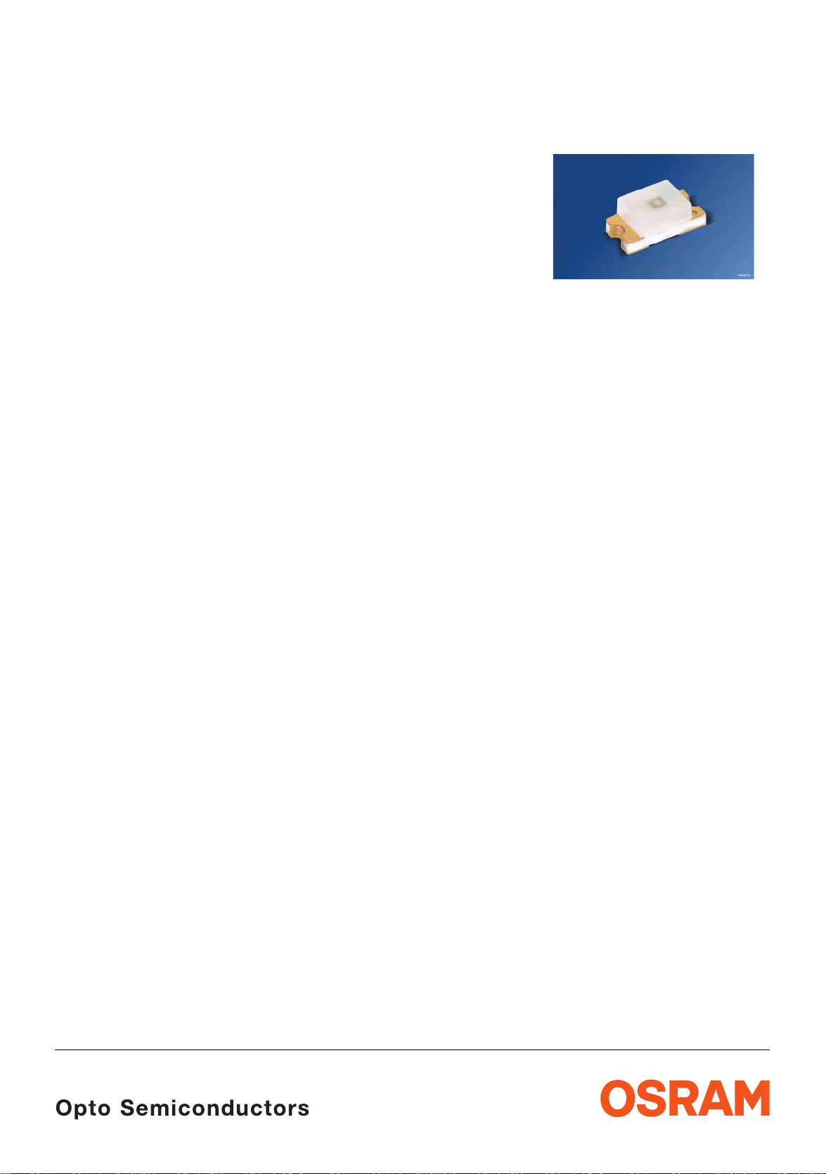
Hyper CHIPLED
Hyper CHIPLED
Hyper-Bright LED
Lead (Pb) Free Product - RoHS Compliant
LS Q976, LO Q976, LY Q976
Besondere Merkmale
• Gehäusetyp: 0603, farbloser diffuser Verguss
• Besonderheit des Bauteils: kleinste Bauform
mm x 0,8 mm x 0,8 mm
1,6
• Wellenlänge: 633 nm (super-rot),
605
nm (orange), 587 nm (gelb)
• Abstrahlwinkel: extrem breite
Abstrahlcharakteristik (160°)
• Technologie: InGaAlP
• optischer Wirkungsgrad: 7 lm/W (super-rot),
lm/W (orange, gelb)
11
• Verarbeitungsmethode: für alle
SMT-Bestücktechniken geeignet
• Lötmethode: IR Reflow Löten
• Vorbehandlung: nach JEDEC Level 2
• Gurtung: 8-mm Gurt mit 4000/Rolle, ø180 mm
• ESD-Festigkeit: ESD-sicher bis 2 kV nach
JESD22-A114-B
Anwendungen
• Informationsanzeigen im Außenbereich
• Flache Hinterleuchtung (LCD, Handy, Schalter,
Display)
• Signal- und Symbolleuchten
• Markierungsbeleuchtung (z.B. Stufen,
Fluchtwege, u.ä.)
Features
• package: 0603, colorless diffused resin
• feature of the device: smallest package
mm x 0.8 mm x 0.8 mm
1.6
• wavelength: 633 nm (super-red),
605
nm (orange), 587 nm (yellow)
• viewing angle: extremely wide (160°)
• technology: InGaAlP
• optical efficiency: 7 lm/W (super-red),
lm/W (orange, yellow)
11
• assembly methods: suitable for all
SMT
assembly methods
• soldering methods: IR reflow soldering
• preconditioning: acc. to JEDEC Level 2
• taping: 8 mm tape with 4000/reel, ø180 mm
• ESD-withstand voltage: up to 2 kV acc. to
JESD22-A114-B
Applications
• outdoor displays
• flat backlighting (LCD, cellular phones,
switches, displays)
• signal and symbol luminaire
• marker lights (e.g. steps, exit ways, etc.)
2006-01-20 1
Page 2
LS Q976, LO Q976, LY Q976
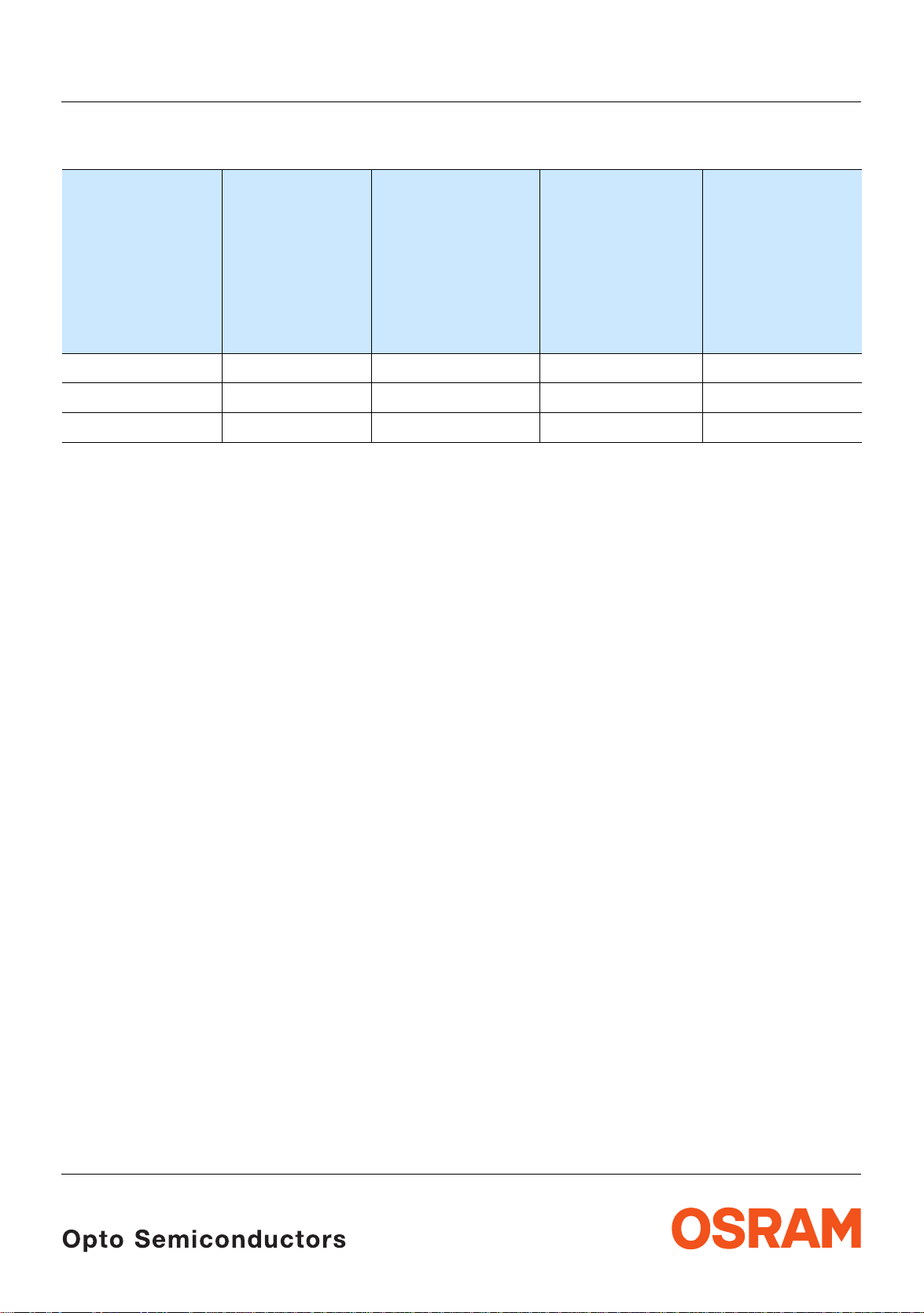
Bestellinformation Ordering Information
1)
Seite 15
Typ
Type
Emissionsfarbe
Color of
Emission
Lichtstärke
Luminous
Intensity
1)
I
= 20 mA
F
I
(mcd)
V
page 15
Lichtstrom
Luminous
Flux
I
Φ
2)
= 20 mA
F
(mlm)
V
LS Q976 super-red 28 ... 180 330 (typ.) Q62702P5187
LO Q976 orange 45 ... 280 520 (typ.) Q62702P5188
LY Q976 yellow 45 ... 280 520 (typ.) Q62702P5276
Anm.: Die oben genannten Typbezeichnungen umfassen die bestellbaren Selektionen. Diese bestehen aus wenigen
Helligkeitsgruppen (sieh e
Gurt geliefert. Z.B.: L Y Q976-P1S2-36 bedeutet, das s auf dem Gurt nur eine der Helligkeitsgru ppen P1, P2,
Q1, Q2, R1, R2, S1 oder S2 enthalten ist.
Um die Liefersicherheit zu gew ährleisten, können einzelne Helligkeitsgruppen nicht beste llt we rden.
Gleiches gilt für die Farben , bei dene n Wellenlä ngengru ppen gem essen und gr uppiert w erden. Pro Gurt wird
nur eine Wellenlängengru ppe geliefert. Z.B.: LY
Wellenlängengruppen -3, -4, -5 oder -6 enthalten ist (siehe
LS Q976-NR-1 bedeutet, dass das Bauteil innerhalb der auf Seite 4 spezifizierten Grenzen gelie fe rt wird .
Um die Liefersicherheit zu gew ährleisten, können einzelne Wellenlängengruppen nicht bes t ellt w erden.
Seite 5 für nähere Inform ationen). Es wird nur eine einzige Helligkeitsgruppe pro
Q976-P1S2-36 bedeutet, dass auf dem Gurt nur eine de r
Seite 5 für nähere Information). Z.B.:
page 15
2)
Seite 15
Bestellnummer
Ordering Code
Note: The above Type Numbers represent the order groups which include only a few brightness groups (see page 5
for explanation). Only o ne group wil l be shipped on each reel (there will be no mixing of two groups on ea ch
reel). E.g. LY
for any one reel.
In order to ensure availability, single brightness groups will not be orderable.
Q976-P1S2-36 means that only one group P1, P2, Q1, Q2, R1, R2, S1 or S2 w ill be shippable
In a similar manner f or c olors wh ere wavele ngth g rou ps are mea sured and bin ned , single wav elengt h grou ps
will be shipped on any one reel. E.g. LY
be shippable (see
specified limits as stated on page 4.
In order to ensure availability , single wavelength groups will not be orderable.
2006-01-20 2
page 5 for explanation). E.g. LS Q976-NR-1 means that the device will be shiped within the
Q976-P1S2-36 means that only 1 wavelength group -3, -4, -5 or -6 will
Page 3
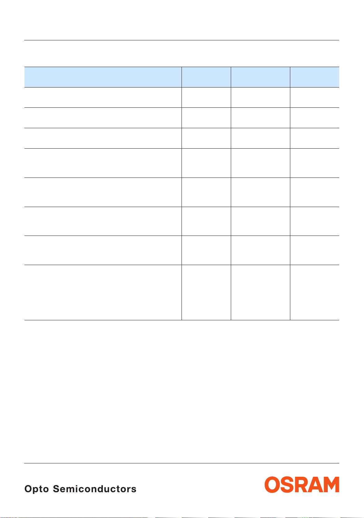
Grenzwerte Maximum Ratings
LS Q976, LO Q976, LY Q976
Bezeichnung
Parameter
Betriebstemperatur
Operating temperature range
Lagertemperatur
Storage temperature range
Sperrschichttemperatur
Junction temperature
Durchlassstrom
Forward current
(TA=25°C)
Stoßstrom
Surge current
t ≤ 10 µs, D = 0.1, T
Sperrspannung
Reverse voltage3)
3)
Seite 15
=25°C
A
page 15
(TA=25°C)
Leistungsaufnahme
Power consumption
(TA=25°C)
Symbol
Symbol
T
op
T
stg
T
j
I
F
I
FM
V
R
P
tot
Wert
Value
Einheit
Unit
– 30 … + 85 °C
– 40 … + 85 °C
+ 95 °C
25 mA
0.1 A
12 V
65 mW
Wärmewiderstand
Thermal resistance
Sperrschicht/Umgebung
4)
Junction/ambient
page 15
Sperrschicht/Lötpad
Junction/solder point
4)
Seite 15
R
R
th JA
th JS
900
510
K/W
K/W
2006-01-20 3
Page 4
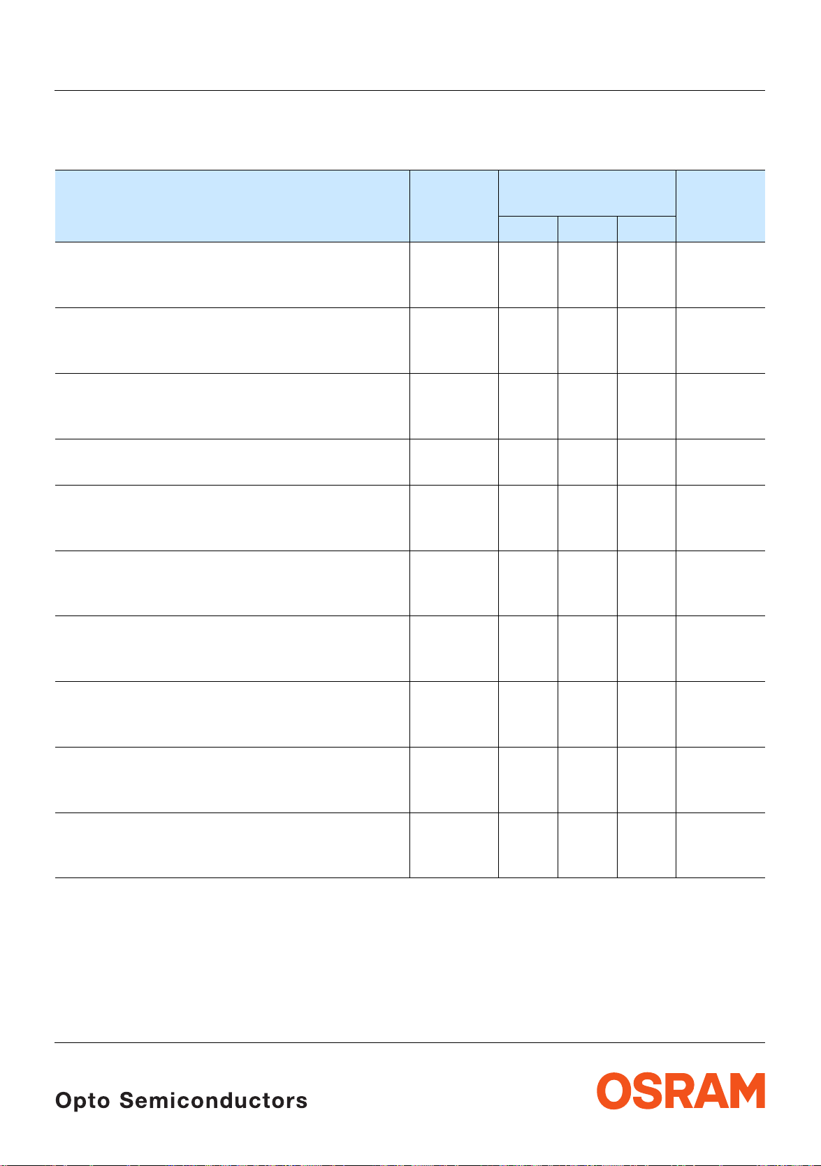
Kennwerte
Characteristics
(TA = 25 °C)
LS Q976, LO Q976, LY Q976
Bezeichnung
Parameter
Wellenlänge des emittierten Lichtes (typ.)
Wavelength at peak emission
I
= 20 mA
F
5)
Dominantwellenlänge
Dominant wavelength5)
I
= 20 mA
F
Spektrale Bandbreite bei 50 % I
Spectral bandwidth at 50 % I
I
= 20 mA
F
Seite 15
page 15
rel max
rel max
(typ.)
Abstrahlwinkel bei 50 % IV (Vollwinkel) (typ.)
Viewing angle at 50 % I
Durchlassspannung
Forward voltage6)
I
= 20 mA
F
6)
Seite 15
page 15
V
(typ.)
(max.)
Sperrstrom (typ.)
Reverse current (max.)
V
= 12 V
R
Temperaturkoeffizient von λ
Temperature coefficient of λ
I
= 20 mA; –10°C ≤ T ≤ 100°C
F
Temperaturkoeffizient von λ
Temperature coefficient of λ
I
= 20 mA; –10°C ≤ T ≤ 100°C
F
Temperaturkoeffizient von V
Temperature coefficient of V
I
= 20 mA; –10°C ≤ T ≤ 100°C
F
peak
peak
dom
dom
F
F
(typ.)
(typ.)
(typ.)
Optischer Wirkungsgrad (typ.)
Optical efficiency
I
= 20 mA
F
* Einzelgruppen siehe Seit e 5
Individual groups on page 5
Symbol
Symbol
Werte
Values
LS LO LY
λ
peak
λ
dom
645 610 591 nm
633
± 6
605*
± 6
587*
–4/+8
∆λ 16 16 15 nm
2ϕ 160 160 160 Grad
V
V
I
R
I
R
TC
TC
TC
η
opt
F
F
λpeak
λdom
V
2.0
2.5
0.01
100
2.0
2.5
0.01
100
2.0
2.5
0.01
100
0.14 0.13 0.13 nm/K
0.05 0.07 0.10 nm/K
– 2.0 – 1.7 – 2.5 mV/K
7 11 11 lm/W
Einheit
Unit
nm
deg.
V
V
µA
µA
2006-01-20 4
Page 5
LS Q976, LO Q976, LY Q976
Wellenlängengruppen (Dominantwellenlänge)
Wavelength Groups (Dominant Wavelength)
Gruppe
Group
gelb
yellow
5)
5)
page 15
Seite 15
orange
orange
Einheit
Unit
min. max. min. max.
2 600 603 nm
3 583 586 603 606 nm
4 586 589 606 609 nm
5 589 592 609 612 nm
6 592 595 nm
Helligkeits-Gruppierungsschema Brightness Groups
Helligkeitsgruppe
Brightness Group
N
P1
P2
Q1
Q2
R1
R2
S1
S2
Lichtstärke
1) Seite 15
Luminous Intensity
IV (mcd)
28 ... 45
45 ... 56
56 ... 71
71 ... 90
90 ... 112
112 ... 140
140 ... 180
180 ... 224
224 ... 280
1)
page 15
Lichtstrom
Luminous Flux
Φ
V
115 (typ.)
160 (typ.)
200 (typ.)
255 (typ.)
325 (typ.)
405 (typ.)
510 (typ.)
645 (typ.)
805 (typ.)
(mlm)
2) Seite 15
2)
page 15
Anm.: Die Standardlieferform von Serientypen beinhaltet eine Familiengruppe. Diese besteht aus
bzw. 8 Helligkeitsgruppen.
4
Einzelne Helligkeitsgr uppen sind nicht bestellbar.
Note: The standard shipping format for serial types includes a family group of 4 or 8 individual brightness gro ups .
Individual brightness groups cannot be ordered.
Gruppenbezeichnung auf Etikett
Group Name on Label
Beispiel: Q2-4
Example: Q2-4
Helligkeitsgruppe
Brightness Groups
Wellenlänge (gelb)
Wavelength (yellow)
Q2 4
Anm.: In einer Verpackungseinheit / Gurt ist immer nur eine Gruppe für jede Selektion enth alt en.
Note: No packing unit / tape ev er c ont ains more than one group for each select ion.
2006-01-20 5
Page 6

LS Q976, LO Q976, LY Q976
Seite 15
Relative spektrale Emission2)
2)
Relative Spectral Emission
page 15
V(λ) = spektrale Augenempfindlichkeit / Standard eye response curve
I
= f (λ); TA = 25 °C; IF = 20 mA
rel
100
%
Ι
rel
80
60
40
20
V
λ
yellow
orange
OHL00555
super-red
0
400
Abstrahlcharakteristik
2)
Radiation Characteristic
I
= f (ϕ); TA = 25 °C
rel
50˚
60˚
70˚
80˚
90˚
Seite 15
2)
page 15
nm450 500 550 600 650 700
λ
0˚10˚20˚40˚ 30˚
ϕ
1.0
OHL00408
0.8
0.6
0.4
0.2
0
100˚
1.0 0.8 0.6 0.4
0˚ 20˚ 40˚ 60˚ 80˚ 100˚ 120˚
2006-01-20 6
Page 7

LS Q976, LO Q976, LY Q976
Durchlassstrom2)
Forward Current
I
= f (VF); TA = 25 °C
F
2
10
mA
5
10
10
1
5
0
5
I
F
2)
-1
10
1.4 1.8 2.2 2.6 3 V 3.4
1
Seite 15
page 15
OHL00232
Relative Lichtstärke
Relative Luminous Intensity
I
V/IV(20 mA)
I
= f (IF); TA = 25 °C
1
10
I
V
V (20 mA)
0
10
2) 7)
Seite 15
2) 7)
page 15
OHL00556
5
10
-1
5
super-red
yellow,
orange
-2
10
5
-3
10
-1 0
10
V
F
Relative Lichtstärke2)
10 10
55
Seite 15
Relative Luminous Intensity
I
V/IV(25 °C)
= f (Tj); IF =20 mA
2.0
I
V
I
(25 ˚C)
V
12
mA
10
I
2)
page 15
OHL02378
1.6
orange
yellow
1.2
super-red
2006-01-20 7
0.8
0.4
0
-20 0
orange
yellow
super-red
20 40 60
T
˚C
100
j
Page 8

LS Q976, LO Q976, LY Q976
Maximal zulässiger Durchlassstrom
Max. Permissible Forward Current
I
= f (T)
F
30
mA
I
F
OHL00873
25
20
T
S
15
T
A
10
5
T
temp. ambient
A
temp. solder point
T
S
0
020406080 ˚C 100
T
Zulässige Impulsbelastbarkeit IF = f (tp)
Permissible Pulse Handling Capability
Duty cycle
0.12
I
F
0.08
0.06
0.04
0.02
D = parameter, T
A
0
-5
10
10-410-310-210-110010
D
=
t
P
T
= 25 °C
A
OHL02140
t
P
T
D
=
0.005
0.01
0.02
0.05
0.1
0.2
0.5
1
I
F
1
2
10s
t
p
Zulässige Impulsbelastbarkeit IF = f (tp)
Permissible Pulse Handling Capability
Duty cycle
D = parameter, T
0.12
A
I
F
0.08
0.06
0.04
0.02
0
-5
10
10-410-310-210-110010
D
=
= 85 °C
A
t
P
t
P
T
D
=
0.005
0.01
0.02
0.05
0.1
0.2
0.5
1
OHL02147
T
t
1
p
I
F
2
10s
2006-01-20 8
Page 9

Maßzeichnung
8)
Package Outlines
Seite 15
8)
page 15
LS Q976, LO Q976, LY Q976
0.9 (0.035)
0.7 (0.028)
ø0.5 (ø0.020)
ø0.3 (ø0.012)
0.9 (0.035)
0.7 (0.028)
0.4 (0.016)
0.2 (0.008)
Cathode
mark
0.9 (0.035)
1.7 (0.067)
1.5 (0.059)
1.1 (0.043)
0.9 (0.035)
0.4 (0.016)
0.2 (0.008)
Gewicht / Approx. weight: 1.4 mg
8)
Gurtung / Polarität und Lage
Seite 15
Verpackungseinheit: 4 Rollen mit 4000/Rolle,
8 mm Gurt, ø180 mm
8)
Method of Taping / Polarity and Orientation
page 15
Packing unit: 4 reels with 4000/reel,
8 mm tape, ø180 mm
0.7 (0.028)
0.5 (0.020)
Cathode mark
Soldering terminal
Soldering terminal
may flow in x, y direction
0.7 (0.028)
C
A
GEOY6989
4 (0.157)
Cathode mark
1.5 (0.059)
4 (0.157)
2 (0.079)
1 (0.039)
2006-01-20 9
1.75 (0.069)
3.5 (0.138)
1.85 (0.073)
8 (0.315)
OHAY0531
C
A
Page 10

Empfohlenes Lötpaddesign
Recommended Solder Pad
8)
8)
page 15
Seite 15
LS Q976, LO Q976, LY Q976
IR Reflow Löten
IR Reflow Soldering
0.7 (0.028)
0.8 (0.031)
0.8 (0.031)
0.8 (0.031)
OHAPY606
Empfohlenes Lötpaddesign verwendbar für Hyper CHIPLED und Chipled - Bauform 0603
8) 9)
Seite 15
IR Reflow Löten
Recommended Solder Pad useable for Hyper CHIPLED and Chipled - Package 0603
8) 9)
page 15
IR Reflow Soldering
2.25 (0.089)
0.225 (0.009)
0.35 (0.014)
0.8 (0.031)
0.3 (0.012)
0.5 (0.020)
2006-01-20 10
0.65 (0.026)
OHPY0203
Page 11

LS Q976, LO Q976, LY Q976
Lötbedingungen Vorbehandlung nach JEDEC Level 2
Soldering Conditions Preconditioning acc. to JEDEC Level 2
IR-Reflow Lötprofil (nach IPC 9501)
IR Reflow Soldering Profile (acc. to IPC 9501)
250
= 245 ˚C
T
˚C
T
200
T
= 183 ˚C = 70 s
t
max
150
100
2-3 K/s
50
0
0:00
0:30 1:00 1:30 2:00 2:30 3:00 3:30 4:00 4:30 5:00 5:30
IR-Reflow Lötprofil für bleifreies Löten (nach J-STD-020B) IR Reflow Soldering Profile for lead free soldering (acc. to J-STD-020B)
300
˚C
250
T
200
255 ˚C
240 ˚C
217 ˚C
Maximum Solder Profile
Recommended Solder Profile
Minimum Solder Profile
30 s max
2-3 K/s
t
10 s min
OHLA0685
260 ˚C
245 ˚C
235 ˚C
min
OHLA0687
+0 ˚C
-5 ˚C
±5 ˚C
+5 ˚C
-0 ˚C
150
120 s max
100
Ramp Up
0
3 K/s (max)
25 ˚C
50 100 150 200 250 300
50
0
2006-01-20 11
Ramp Down
6 K/s (max)
100 s max
s
t
Page 12

Barcode-Produkt-Etikett (BPL) Barcode-Product-Label (BPL)
LS Q976, LO Q976, LY Q976
Gurtverpackung Tape and Reel
OSRAM Opto
Semiconductors
(6P) BATCH NO: Batch Number
Bar Code
Lot Number(1T) LOT NO: (9D) D/C: Date Code
Bar Code
(X) PROD NO: Product Code
D
0
P
0
P
2
Bin1: Bin Information Color 1
Lx xxxx
Product Name
RoHS Compliant
Product Quantity per Reel(Q)QTY:
Bar Code
Sample
W
1
±0.25
13.0
FE
A
N
W
Bin2:
Bin3:
ML2Temp ST
260 C RT
Additional TEXT
R077 DEMY
PACKVAR: Packing Type
X - X - X(G) GROUP:
Forward Voltage Group
Wavelength Group
Brightness Group
OHA12043
P
1
Direction of unreeling
W
2
Label
Gurtvorlauf:
Leader:
Gurtende:
Trailer:
Direction of unreeling
400 mm
400 mm
160 mm
160 mm
OHAY0324
Tape dimensions in mm (inc h)
W P
+ 0.3
8
– 0.1
0
4 ± 0.1
(0.157 ± 0.004)
P
1
4 ± 0.1
(0.157 ± 0.004)
P
2
2 ± 0.05
(0.079 ± 0.002)
D
0
1.5 + 0.1
(0.059 + 0.004)
E F
1.75 ± 0.1
(0.069 ± 0.004)
3.5 ± 0.05
(0.138 ± 0.002)
Reel dimensions in mm (inc h)
A W N
min
W
1
W
2 max
180 (7) 8 (0.315) 60 (2.362) 8.4 + 2 (0.331 + 0.079) 14.4 (0.567)
2006-01-20 12
Page 13

LS Q976, LO Q976, LY Q976
Trockenverpackung und Materialien
Dry Packing Process and Materials
Moisture-sensitive label or print
L
E
V
l
E
e
e
b
L
a
se
.
l
,
)
e
k
H
d
n
o
la
R
c
b
(
r
f
I
a
y
t
b
.
i
d
H
i
R
m
u
%
h
0
e
6
e
/
v
i
g
d
t
C
a
e
˚
a
r
l
k
a
0
c
e
r
S
r
f
3
a
N
E
s
R
n
p
_
<
V
i
n
%
I
i
f
O
k
0
o
T
s
a
o
t
T
I
a
r
t
9
IO
e
.
s
S
u
s
C
n
d
)
r
r
<
p
n
o
e
N
o
U
(
e
T
o
u
s
t
o
d
c
E
D
S
g
N
U
a
O
E
b
C
A
R
I
s
U
i
M
T
h
C
E
T
S
<
I
S
t
O
a
O
t
M
T
s
a
h
P
h
t
v
t
i
n
O
u
s
o
q
e
m
c
e
i
r
e
v
4
o
d
e
2
,
o
d
:
c
,
g
w
r
d
a
o
s
l
a
e
b
f
e
b
n
e
d
r
e
m
e
e
i
l
p
t
e
e
a
o
s
r
s
e
a
e
o
,
s
.
i
s
h
k
b
o
l
H
p
n
,
r
g
n
-
i
F
a
n
g
r
R
a
a
l
i
n
e
o
b
C
b
h
i
f
t
i
p
%
i
k
l
f
r
s
.
.
i
I
t
a
0
a
f
o
p
w
l
h
v
t
e
1
b
t
e
,
a
m
d
_
<
r
m
,
h
e
c
e
e
w
i
r
e
t
t
t
t
d
i
S
t
o
d
E
f
o
a
n
e
l
u
y
.
f
r
n
n
u
D
i
A
I
q
d
1
d
e
o
u
.
r
e
E
o
s
e
y
i
r
r
q
t
2
J
b
i
M
/
o
e
s
b
d
t
)
r
i
C
e
2
a
S
s
c
P
r
m
i
i
I
)
o
u
v
b
g
e
e
H
a
n
c
i
D
e
)
2
n
t
k
.
a
o
)
e
a
a
r
3
b
d
b
e
e
f
l
f
I
m
e
a
i
r
.
t
e
v
4
s
d
e
n
L
g
a
a
e
L
r
B
e
t
u
e
t
r
a
s
u
e
i
t
D
r
o
s
u
i
t
M
o
s
u
i
t
M
o
s
i
M
o
M
r
H
i
d
,
c
o
t
g
n
s
i
u
o
e
r
C
2
n
H
j
a
d
o
i
c
˚
u
7
b
s
n
8
H
o
e
5
C
u
s
o
t
4
˚
e
s
4
H
e
c
a
±
c
2
0
m
d
e
e
y
6
i
o
4
r
t
C
b
r
h
˚
m
e
o
l
r
i
t
p
t
l
i
t
.
i
o
3
c
m
t
e
)
r
i
w
o
2
w
t
a
n
l
o
C
l
f
m
t
i
˚
r
e
.
F
o
a
t
l
t
l
a
o
e
c
a
a
r
i
r
F
l
o
t
d
l
o
u
e
n
:
a
F
o
f
d
l
b
4
i
e
e
w
e
l
r
a
F
,
d
l
o
i
5
c
l
e
g
a
n
l
o
v
e
s
n
5
r
i
e
e
i
e
b
t
l
p
h
v
6
L
e
n
e
e
t
e
l
w
e
v
u
e
e
a
L
k
e
r
e
o
d
v
a
%
u
e
L
l
t
r
m
e
b
0
s
a
u
e
L
i
r
1
t
e
r
e
r
o
o
s
e
u
s
f
i
>
t
o
r
f
M
,
o
s
u
s
3
i
k
i
t
3
M
o
s
n
i
d
0
a
M
o
l
b
D
M
f
r
T
i
(
a
S
r
s
e
a
J
k
s
Y
e
r
e
C
1
u
e
Y
o
>
1
W
H
e
4
8
m
e
6
i
t
1
m
:
e
r
i
t
d
o
m
e
r
e
i
o
t
l
o
n
m
i
r
F
o
e
t
l
o
p
r
F
o
l
o
F
o
l
1
l
F
2
e
a
l
2
e
l
v
3
e
e
l
v
e
e
v
L
e
L
e
r
M
A
R
S
O
Desiccant
Anm.: Feuchteempfindliche Produkte sind verpackt in einem Trockenbeutel z us am m en mit einem Trockenmittel und
einer Feuchteindikatorkarte
Bezüglich Trockenverpackung finden Sie weitere Hinweise im Internet und in unserem Short Form Catalog im
Kapitel “Gurtung und V erpackung” unter dem Punkt “Trockenve rpackung”. Hier sind Normenbezüge, unter
anderem ein Auszug der JED EC-Norm, enthalten.
Note: Moisture-senisitve pro duc t is packed in a dry bag containing des ic c ant and a humidity card.
Regarding dry pack y ou will find further informat ion in the internet and in the Short Form Catalog i n chapter
“Tape and Reel” under the topic “Dry Pack”. Here you will also find the normative references like JEDE C.
Kartonverpackung und Materialien Transportation Packing and Materials
Barcode label
Do not eat.
Avoid metal contact.
Discard if circles overrun.
bag opening.
Please check the HIC immidiately after
check dot
WET
Comparator
bake units
15%
examine units, if necessary
If wet,
bake units
10%
examine units, if necessary
If wet,
change desiccant
5%
parts still adequately dry.
If wet,
MIL-I-8835
Humidity Indicator
OSRAM
Humidity indicator
Barcode label
OHA00539
O
S
Semiconductors
R
A
M
(6P) BA
O
TCH NO:
(1T) LOT
2
1
0
NO:
0
2
1
2
(X) PROD NO:
3
G
H
1
2
3
4
11
(9D) D/C:
0
0
1
245
(Q)QTY:
2
0
0
0
Muster
2006-01-20 13
p
to
1
9
9
8
M
u
L
lti T
S
0
Y
1
T
4
O
4
6
P
7
L
6
E
Bin1: P-1-20
D
Bin2: Q-1-20
B
in3:
ML
2
Temp ST
2a
220 C R
3
240 C R
260 C RT
Additional TEXT
R077
PACKVAR:
(G) GROUP:
R
1
DEMY
8
P
-1
+
Q
-1
OHA02624
Page 14

LS Q976, LO Q976, LY Q976
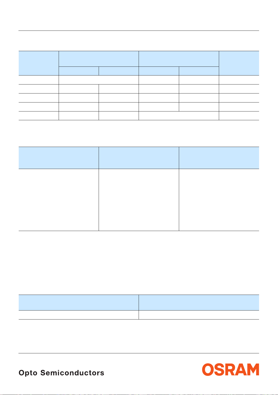
Revision History: 2006-01-20
Previous Version: 2005-06-28
Page Subjects (major changes since last revision) Date of change
4 value (wavelength yellow)
11 recommended solder pad
2 color of the light emitting area
3 pad size from 16 mm2 to 5 mm
13 annotations 2002-07-25
2
4 value (TC
from 0.01 to 0.05 nm/K) 2002-07-25
λdom
3, 4 value (reverse voltage from 5 V to 12 V) 2002-09-18
2 ordering code 2002-09-19
3 ambient temperature 2003-09-09
5 Wavelength groups for dominant wavelength 2003-09-26
all new template 2003-10-29
8 Permissible Pulse Handling Capability 2004-01-22
1 RoHS compliant 2004-04-20
1 ESD-withstand voltage 2004-08-30
12 Product Label acc. to OS-IN-2005-015 2005-05-18
Attention please!
The information describes the type of component and shall not be c ons idered as assured characteris tics .
Terms of delivery and rights to change design reserved. Due to technical requirements components may contain
dangerous substances . For in fo rmation on the types in question pleas e c ont ac t our Sales Organization.
If printed or downloaded, please find the latest version in the Internet .
Packing
Please use the recycling operators k nown to you . We can als o help you – get in touch wit h your near est sales offic e.
By agreement we will take p acking material back, if it is sorted. You m ust bear the costs of transport. For packing
material that is returned to us unsorted or which we are not obliged to accept, we shall have to invoice you for any costs
incurred.
Components used in life-su pport devices or systems must be expressly authorized fo r such purpose! Critical
components
OSRAM OS.
2006-01-20 14
10) page 15
may only be used in l ife-s upport devices or s ystems
11) page 15
with the express writte n appro val of
Page 15

LS Q976, LO Q976, LY Q976
Fußnoten:
1)
Helligkeitswerte werden mit einer
Stromeinprägedauer von 25
Genauigkeit von ±
2)
Wegen der besonderen Prozessbedingun gen bei der
11% ermitt elt.
ms und einer
Herstellung von LED können typische oder abgeleitete
technische Parameter nur aufgrund statistischer
Werte wiedergegeben werden. Diese stimmen nicht
notwendigerweise mit den Werten jedes einzelnen
Produktes überein, dessen Werte sich von typischen
und abgeleiteten Werten oder typischen Kennlinien
unterscheiden können. Falls erforderlich, z.B.
aufgrund technischer Ve rbesserungen, werde n diese
typischen Werte ohne weitere Ankündigung geändert.
3)
Die LED kann kurzzeitig in Sperrichtung betrieben
werden.
4)
R
ergibt sich bei Montage auf PC-Board FR 4
thJA
(Padgröße
5)
Wellenlängen werden mit einer Stromeinprägedauer
von 25
6)
Spannungswerte werden mit einer
Stromeinprägedauer vo n 1
von ±0,1
7)
Im gestrichelten Bereich der Kennlinien muss mit
≥ 5 mm2 je Pad)
ms und einer Genauigkeit von ±1 nm ermittelt.
ms und einer Genauigk eit
V ermittelt.
erhöhten Helligkeitsunterschieden zwischen
Leuchtdioden innerhalb einer Verpackungseinheit
gerechnet werden.
8)
Maße werden wie folgt angegeben: mm (inch)
9)
Empfohlene Lötpastendicke: 120 µm
10)
Ein kritisches Bauteil ist ein Bauteil, das in
lebenserhaltenden Apparaten oder Systemen
eingesetzt wird und de ssen Defek t voraussich tlich zu
einer Fehlfunktion dieses lebenserhaltenden
Apparates oder Systems führen wird oder die
Sicherheit oder Effektivität dieses Apparates oder
Systems beeinträchtigt.
11)
Lebenserhaltende App arate oder Systeme sind für
(a) die Implantierung in den menschlichen Körper
oder
(b) für die Lebenserhaltung bestimmt.
Falls sie versagen, kann davon ausgegangen werden,
dass die Gesundheit und das Leben des Patie nten in
Gefahr ist.
Remarks:
1)
Brightness groups are tested at a current pulse
duration of 25
2)
Due to the special conditions of the manufacturing
ms and a tolera nce of ± 11%.
processes of LED, the typical data or calculated
correlations of technical parameters can only reflect
statistical figures. These do not necessarily
correspond to the actual parameters of each single
product, which could differ from t he typical data and
calculated correlations or the typical characteristic
line. If requested, e.g. because of technical
improvements, these typ. data will be changed without
any further notice.
3)
Driving the LED in reverse direction is suitable for
short term application.
4)
R
results from mounting on PC board FR 4 (pad
thJA
size
5)
6)
7)
≥ 5 mm2 per pad)
Wavelengths are tested at a current pu lse duration of
ms and a tolerance of ±1 nm.
25
Forward voltages are tested at a current pulse
duration of 1
ms and a tolerance of ±0.1 V.
In the range where the line of the graph is broken, you
must expect higher brightness differences between
single LEDs within one pack ing unit.
8)
Dimensions are specified as follows: mm (inch).
9)
Recommended thickness of solder paste: 120 µm
10)
A critical component is a component used in a
life-support device or system whose failure can
reasonably be expected to cause the failure of that
life-support device or system , or to affect its safety or
the effectiveness of that device or system.
11)
Life support devices or system s are intended
(a) to be implanted in the human body,
or
(b) to support and/or maintain and s us ta in human life.
If they fail, it is reasonable to assume that the health
and the life of the user may be endangered.
Published by
OSRAM Opto Semiconductors GmbH
Wernerwerkstrasse 2, D-93049 Regensburg
www.osram-os.com
© All Rights Reserved.
2006-01-20 15
 Loading...