

Page 1
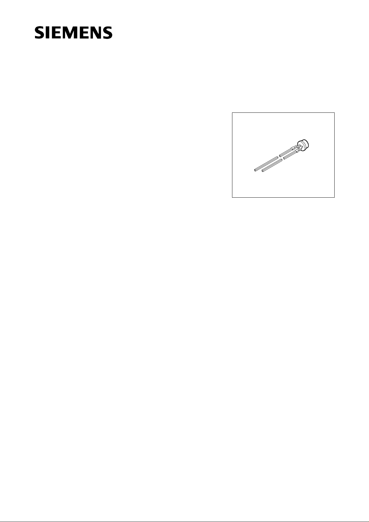
Plane MULTILED
®
3 mm (T1) LED, Non Diffused
Besondere Merkmale
● farbloses, klares Gehäuse
● zur Einkopplung in Lichtleiter
● als optischer Indikator einsetzbar
● antiparallel geschaltete Leuchtdiodenchips
● hohe Signalwirkung durch Farbwechsel der LED möglich
● bei geeigneter Ansteuerung mit IC (z.B. SDA 2231),
Farbwechsel von grün über gelb bis orange (bzw. bis
super-rot) möglich
● Lötspieße mit Aufsetzebene
● gegurtet lieferbar
● Störimpulsfest nach DIN 40839
LSP P370, LOP P370
VEX06712
Features
● colorless, clear package
● for optical coupling into light pipes
● for use as optical indicator
● antiparallel chips
● high signal efficiency possible by color change of the LED
● with appropriate controlling by IC (e.g. SDA 2231) it is possible to change color from green to
yellow and orange (resp. to super-red)
● solder leads with stand-off
● available taped on reel
● load dump resistant acc. to DIN 40839
Semiconductor Group 0 11.96
Page 2
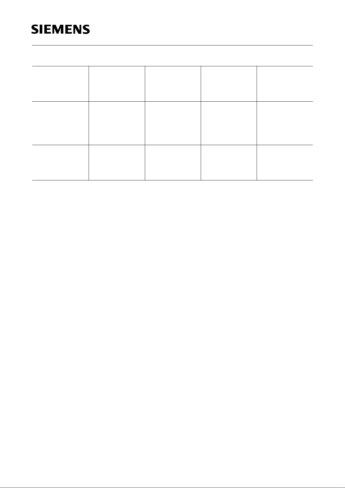
LSP P370, LOP P370
Typ
Type
Emissionsfarbe
Color of
Emission
Gehäusefarbe
Color of
Package
Lichtstrom
Luminous Flux
I
= 15 mA
F
Bestellnummer
Ordering Code
ΦV(mlm)
LSP P370-KN
LSP P370-M
LSP P370-N
LSP P370-P
LSP P370-MQ
LOP P370-KN
LOP P370-M
LOP P370-N
LOP P370-MQ
Streuung des Lichtstromes in einer Verpackungseinheit Φ
Streuung des Lichtstromes in einer LED Φ
1)
Bei MULTILED® bestimmt die Helligkeit des jeweils dunkleren Chips in einem Gehäuse die Helligkeitsgruppe
der LED.
Luminous flux ratio in one packaging unit Φ
Luminous flux ratio in one LED Φ
1)
In case of MULTILED®, the brightness of the darker chip in one packaging unit determines the brightness
group of the LED.
super-red /
pure green
orange /
pure green
V max
colorless clear 6.3 … 50
16.0 … 32
25.0 … 50
40.0 … 80
16.0 … 125
colorless clear 6.3 … 50
16.0 … 32
25.0 … 50
16.0 … 125
/ Φ
/ Φ
V max
V min
V max
≤ 4.0.
/ Φ
/ Φ
V min
V min
V max
≤ 4.0.
≤ 2.0.
V min
1)
≤ 2.0.
Q62703-Q2439
Q62703-Q2671
Q62703-Q2672
Q62703-Q3232
Q62703-Q2673
Q62703-Q2530
Q62703-Q2674
Q62703-Q2675
Q62703-Q2676
1)
Semiconductor Group 1
Page 3
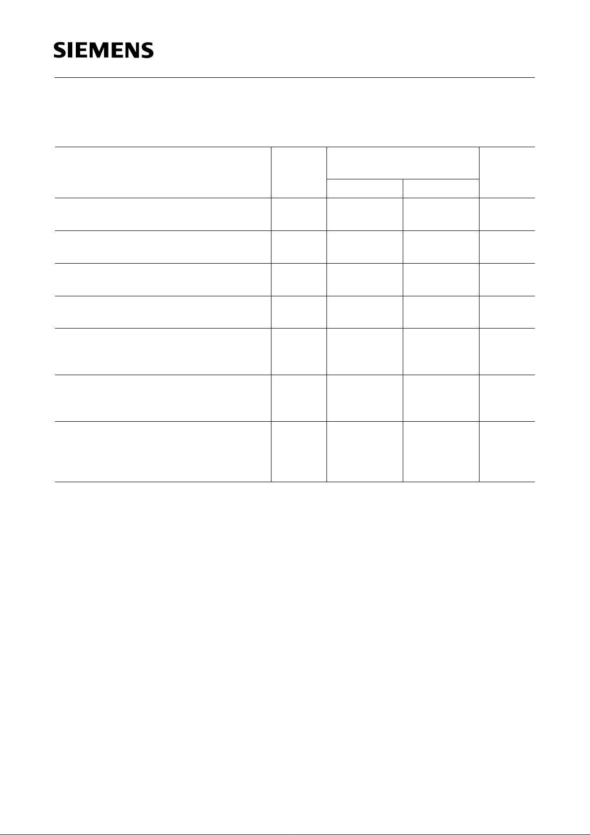
Grenzwerte
Maximum Ratings
LSP P370, LOP P370
Bezeichnung
Parameter
Betriebstemperatur
Operating temperature range
Lagertemperatur
Storage temperature range
Sperrschichttemperatur
Junction temperature
Durchlaßstrom
Forward current
Stoßstrom
Surge current
t ≤ 10 µs, D = 0.005
Verlustleistung
Power dissipation
T
≤ 25 °C
A
Wärmewiderstand
Thermal resistance
Sperrschicht / Luft
Junction / air
Symbol
Symbol
T
op
T
stg
T
j
I
F
I
FM
P
tot
R
th JA
Werte
Values
Einheit
Unit
LS, LO LP
– 55 ... + 100 – 55 ... + 100 ˚C
– 55 ... + 100 – 55 ... + 100 ˚C
+ 100 + 100 ˚C
40
1)
30
1)
mA
0.5 0.5 A
140 100 mW
400 400 K/W
1)
Die angegebenen Grenzdaten gelten für den Chip, für den sie angegeben sind, unabhängig vom
Betriebszustand des anderen.
1)
The stated maximum ratings refer to the specified chip, regardless of the other one’s operating status.
Semiconductor Group 2
Page 4

Kennwerte (TA = 25 ˚C)
Characteristics
LSP P370, LOP P370
Bezeichnung
Parameter
Wellenlänge des emittierten Lichtes (typ.)
Wavelength at peak emission (typ.)
I
= 20 mA
F
Dominantwellenlänge (typ.)
Dominant wavelength (typ.)
I
= 20 mA
F
Spektrale Bandbreite bei 50 % Φ
Spectral bandwidth at 50 % Φ
I
= 20 mA
F
rel max
(typ.)
rel max
(typ.)
Durchlaßspannung (typ.)
Forward voltage (max.)
I
= 15 mA
F
1)
Kapazität
Capacitance
V
= 0 V, f = 1 MHz
R
(typ.)
1)
Schaltzeiten:
Switching times:
I
from 10 % to 90 % (typ.)
V
I
from 90 % to 10 % (typ.)
V
I
= 100 mA, tp = 10 µs, RL = 50 Ω
F
Symbol
Symbol
Werte
Values
Einheit
Unit
LS LO LP
λ
peak
λ
dom
635 610 557 nm
628 605 560 nm
∆λ 45 40 22 nm
V
V
C
t
t
F
F
0
r
f
2.1
2.6
2.1
2.6
2.1
2.6
V
V
12 8 15 pF
300
150
300
150
450
200
ns
ns
1)
Die Gesamtkapazität ergibt sich aus der Summe der Einzelkapazitäten.
1)
The total capacitance results from the sum of the single capacitances.
Semiconductor Group 3
Page 5

LSP P370, LOP P370
Relative spektrale Emission Φ
= f (λ), TA = 25 ˚C, IF= 20 mA
rel
Relative spectral emission
V (λ) = spektrale Augenempfindlichkeit
Standard eye response curve
Abstrahlcharakteristik Φ
Radiation characteristic
= f (ϕ)
rel
Semiconductor Group 4
Page 6

LSP P370, LOP P370
Durchlaßstrom IF = f (VF)
Forward current
T
= 25 ˚C
A
Relativer Lichtstrom ΦV / Φ
Relative luminous flux
T
= 25 ˚C
A
V(15 mA)
= f (IF)
I
Zulässige Impulsbelastbarkeit
= f (tp)
F
Permissible pulse handling capability
Duty cycle D = parameter, TA = 25 ˚C
LS, LO
I
Zulässige Impulsbelastbarkeit
= f (tp)
F
Permissible pulse handling capability
Duty cycle D = parameter, TA = 25 ˚C
LP
Semiconductor Group 5
Page 7

LSP P370, LOP P370
Maximal zulässiger Durchlaßstrom
Max. permissible forward current
I
= f (TA), LS, LO
F
Maximal zulässiger Durchlaßstrom
Max. permissible forward current
I
= f (TA), LP
F
Wellenlänge der Stahlung λ
peak
Wavelength at peak emission
I
= 20 mA
F
= f (TA)
Dominantwellenlänge λ
Dominant wavelength
I
= 20 mA
F
= f (TA)
dom
Semiconductor Group 6
Page 8

LSP P370, LOP P370
Durchlaßspannung VF = f (TA)
Forward voltage
I
= 15 mA
F
Relativer Lichtstrom ΦV / Φ
Relative luminous flux
I
= 15 mA
F
V(25 ˚C)
= f (TA)
Semiconductor Group 7
Page 9

LSP P370, LOP P370
Maßzeichnung (Maße in mm, wenn nicht anders angegeben)
Package Outlines (Dimensions in mm, unless otherwise specified)
Cathode mark, pure green: Long solder lead
Cathode mark, red, orange: Short solder lead
GEX06816
Semiconductor Group 8
 Loading...