

Page 1
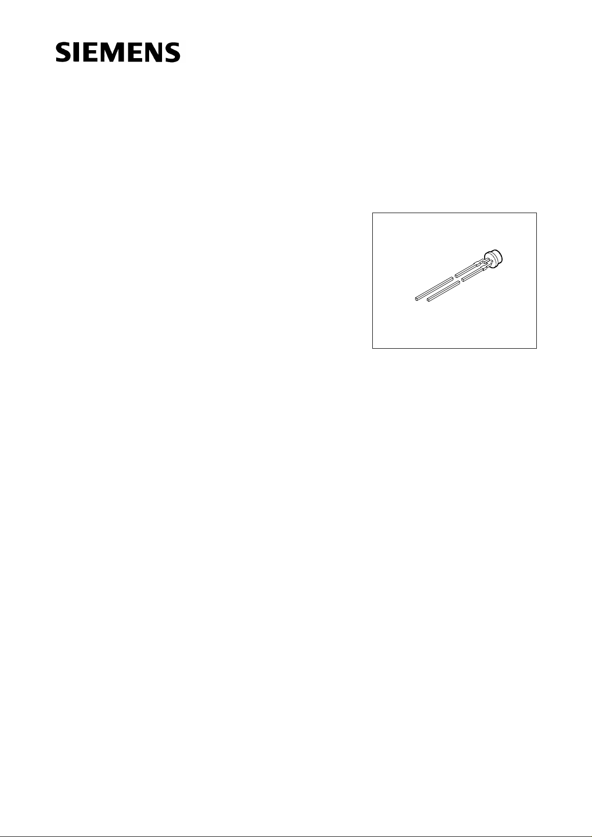
Super Multi ARGUS® LED
High-Current, 3 mm (T1) LED, Non Diffused
Besondere Merkmale
● farbloses, klares Gehäuse
● Kunststoffgehäuse mit spezieller Formgebung
● antiparallel geschaltete Leuchtdiodenchips
● besonders geeignet bei hohem Umfeldlicht durch erhöhten
Betriebsstrom (typ. 50 mA)
● hohe Signalwirkung durch Farbwechsel der LED möglich
● bei Einsatz eines äußeren Reflektors zur Hintergrundbe-
leuchtung von Leuchtfeldern und LCD-Anzeigen geeignet
● zur Direkteinkopplung in Lichtleiter geeignet
● gleichmäßige Ausleuchtung einer Streuscheibe (Weiß-
druck) vor dem äußeren Reflektor
● Lötspieße mit Aufsetzebene
● gegurtet lieferbar
● Störimpulsfest nach DIN 40839
LSG K372, LSP K372
VEX06712
Features
● colorless, clear package
● plastic package with a special design
● antiparallel chip
● appropriate for high ambient light because of the higher operating current (typ. 50 mA)
● high signal efficiency possible by color change of the LED
● in connection with an additional, custom built reflector suitable for backlighting of display panels
● for optical coupling into light pipes
● uniform illumination of a diffuser screen in front of the custom built reflector
● solder leads with stand-off
● available taped on reel
● load dump resistant acc. to DIN 40839
Semiconductor Group 1 11.96
Page 2
LSG K372, LSP K372
Typ
Type
Emissionsfarbe
Color of
Emission
Gehäusefarbe
Color of
Package
Lichtstrom
Luminous Flux
I
= 50 mA
F
Bestellnummer
Ordering Code
ΦV(mlm)
LSG K372-QO super-red / green colorless clear ≥ 100 (160 typ.) Q62703-Q2647
LSP K372-PO super-red /
colorless clear ≥ 40 (100 typ.) Q62703-Q2380
pure green
Streuung des Lichtstromes in einer Verpackungseinheit Φ
Streuung des Lichtstromes in einer LED Φ
1)
Bei MULTILED® bestimmt die Helligkeit des jeweils dunkleren Chips in einem Gehäuse die Helligkeitsgruppe
der LED.
Luminous flux ratio in one packaging unit Φ
Luminous flux ratio in one LED Φ
1)
In case of MULTILED®, the brightness of the darker chip in one package determines the brightness group of
the LED.
V max
/ Φ
/ Φ
V max
/ Φ
V max
≤ 3.0 (L*G K372), ≤ 4.0 (L*P K372).
V min
≤ 3.0 (L*G K372), ≤ 4.0 (L*P K372).
V min
≤ 2.0.
V min
V max
/ Φ
1)
V min
≤ 2.0.
1)
Semiconductor Group 2
Page 3
LSG K372, LSP K372
Grenzwerte
Maximum Ratings
1)
1)
Bezeichnung
Parameter
Betriebstemperatur
Operating temperature range
Lagertemperatur
Storage temperature range
Sperrschichttemperatur
Junction temperature
Durchlaßstrom
Forward current
Stoßstrom
Surge current
t ≤ 10 µs, D = 0.005
Verlustleistung
Power dissipation
T
≤ 25 °C
A
Wärmewiderstand
Termal resistance
Sperrschicht / Luft
Junction / air
Symbol
Symbol
T
op
T
stg
T
j
I
F
I
FM
P
tot
2)
R
th JA
Werte
Values
Einheit
Unit
– 55 ... + 100 ˚C
– 55 ... + 100 ˚C
+ 100 ˚C
75 mA
1A
240 mW
250 K/W
1)
Die angegebenen Grenzwerte gelten für den Chip, für den sie angegeben sind, unabhängig vom
Betriebszustand des anderen.
2)
Montiert auf Platine mit min. Anschlußlänge (bis Aufsatzebene, Lötfläche ≥ 16 mm2).
1)
The stated maximum ratings refer to the specified chip regardless of the other one’s status.
2)
Mounted on PC board with min. lead length (up to stand-off, pad size ≥ 16 mm2).
Semiconductor Group 3
Page 4

Kennwerte (TA = 25 °C)
Characteristics
LSG K372, LSP K372
Bezeichnung
Parameter
Wellenlänge des emittierten Lichtes (typ.)
Wavelength at peak emission (typ.)
I
= 20 mA
F
Dominantwellenlänge (typ.)
Dominant wavelength (typ.)
I
= 20 mA
F
Spektrale Bandbreite bei 50 % Φ
Spectral bandwidth at 50 % Φ
I
= 20 mA
F
rel max
(typ.)
rel max
(typ.)
Durchlaßspannung (typ.)
Forward voltage (max.)
I
= 50 mA
F
1)
Kapazität
Capacitance
V
= 0 V, f = 1 MHz
R
(typ.)
1)
Schaltzeiten:
Switching times:
I
from 10 % to 90 % (typ.)
V
I
from 90 % to 10 % (typ.)
V
I
= 100 mA, tp = 10 µs, RL = 50 Ω
F
Symbol
Symbol
Wert
Value
Einheit
Unit
SGP
λ
λ
peak
dom
635 565 557 nm
628 570 560 nm
∆λ 45 25 22 nm
V
V
C
t
t
F
F
0
r
f
2.0
3.8
2.6
3.8
2.6
3.8
V
V
55 55 80 pF
300
150
450
200
450
200
ns
ns
1)
Die Gesamtkapazität ergibt sich aus der Summe der Einzelkapazitäten.
1)
The total capacitance results from the sum of the single capacitances.
Semiconductor Group 4
Page 5

LSG K372, LSP K372
Relative spektrale Emission Φ
= f (λ), TA = 25 ˚C, IF= 20 mA
rel
Relative spectral emission
V (λ) = spektrale Augenempfindlichkeit
Standard eye response curve
Abstrahlcharakteristik Φ
Radiation characteristic
= f (ϕ)
rel
Semiconductor Group 5
Page 6

LSG K372, LSP K372
Durchlaßstrom, Pulsbetrieb IF = f (VF)
Forward current, pulsed
T
= 25 ˚C
A
Relativer Lichtstrom ΦV / Φ
Relative luminous flux
T
= 25 ˚C
A
V(50 mA)
= f (IF)
Maximal zulässiger Durchlaßstrom
Max. permissible forward current
I
= f (TA)
F
Zulässige Impulsbelastbarkeit
I
= f (tP)
F
Permissible pulse handling capability
Duty cycle D = parameter, TA= 25 ˚C
Semiconductor Group 6
Page 7

LSG K372, LSP K372
Wellenlänge der Stahlung λ
peak
Wavelength at peak emission
I
= 20 mA
F
= f (TA)
Dominantwellenlänge λ
Dominant wavelength
I
= 20 mA
F
= f (TA)
dom
Durchlaßspannung
Forward voltage
I
= 50 mA
F
V
= f (TA)
F
Relativer Lichtstrom Φ
Relative luminous flux
I
= 50 mA
F
/ Φ
V
V(25 ˚C)
= f (TA)
Semiconductor Group 7
Page 8

LSG K372, LSP K372
Maßzeichnung (Maße in mm, wenn nicht anders angegeben)
Package Outlines (Dimensions in mm, unless otherwise specified)
GEX06805
Kathodenkennzeichnung:
rot: kürzerer Lötspieß
grün: längerer Lötspieß
Cathode mark:
red: shorter solder lead
green: longer solder lead
Semiconductor Group 8
 Loading...