

Page 1
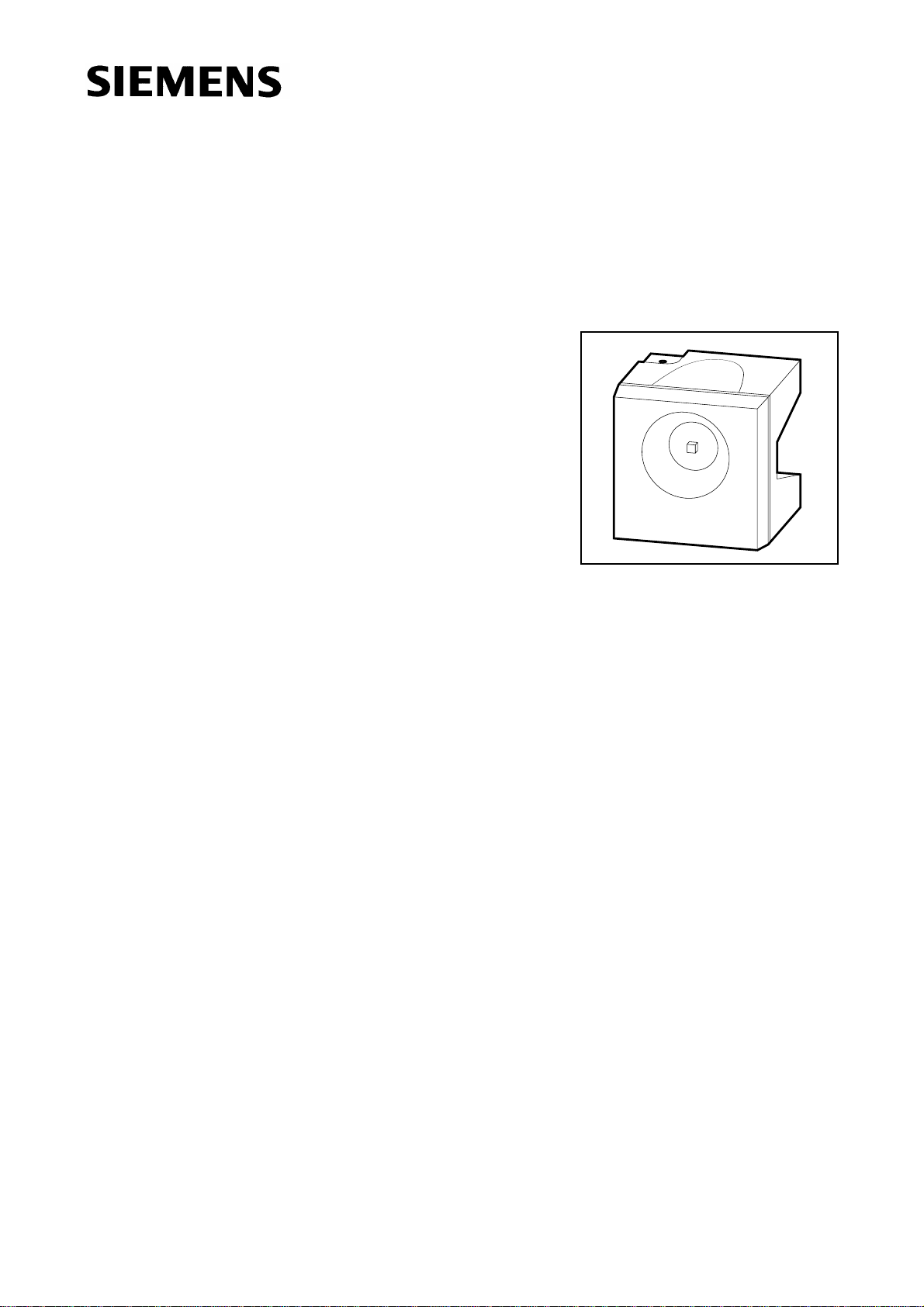
Super SIDELED
®
High-Current LED
Besondere Merkmale
● Gehäusefarbe: weiß
● als optischer Indikator einsetzbar
● besonders geeignet bei hohem Umgebungslicht durch
erhöhten Betriebsstrom (≤ 50 mA DC)
● zur Hinterleuchtung, Lichtleiter- und Linseneinkopplung
● für alle SMT-Bestück- und Reflow-Löttechniken geeignet
● gegurtet (12-mm-Filmgurt)
● Störimpulsfest nach DIN 40839
LS A672, LO A672, LY A672
LG A672, LP A672
Features
● color of package: white
● for use as optical indicator
● appropriate for high ambient light because of the higher
operating current (≤ 50 mA DC)
● for backlighting, optical coupling into light pipes and lenses
● suitable for all SMT assembly and reflow soldering methods
● available taped on reel (12 mm tape)
● load dump resistant acc. to DIN 40839
VPL06880
Semiconductor Group 1 1998-11-12
Page 2
LS A672, LO A672, LY A672
LG A672, LP A672
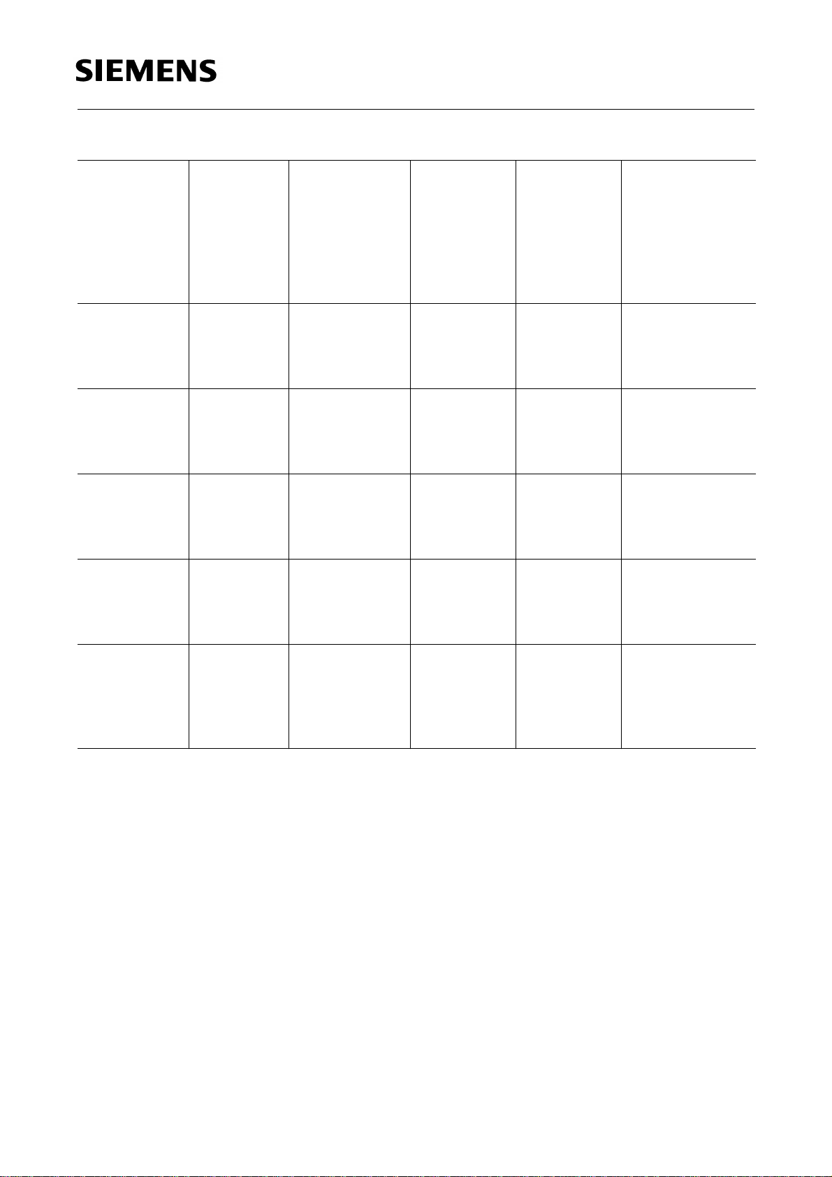
Typ
Type
■
LS A672-LP
■
LS A672-N
■
LS A672-P
■
LS A672-NR
■
LO A672-LP
■
LO A672-N
■
LO A672-P
■
LO A672-NR
■
LY A672-LN
■
LY A672-N
■
LY A672-P
■
LY A672-MQ
LG A672-LP
LG A672-N
LG A672-P
LG A672-MQ
Emissionsfarbe
Farbe der
Lichtaustritts-
Lichtstärke
fläche
Color of
Emission
Color of the
Light Emitting
Area
Luminous
Intensity
I
= 50 mA
F
I
(mcd)
V
super-red colorless clear 10 ... 80
25 ... 50
40 ... 80
25 ... 200
orange colorless clear 10 ... 80
25 ... 50
40 ... 80
25 ... 200
yellow colorless clear 10 ... 50
25 ... 50
40 ... 80
16 ... 125
green colorless clear 10 ... 80
25 ... 50
40 ... 80
16 ... 125
Lichtstrom
Luminous
Flux
I
= 50 mA
F
ΦV (mlm)
100 (typ.)
180 (typ.)
-
100 (typ.)
180 (typ.)
-
100 (typ.)
180 (typ.)
-
100 (typ.)
180 (typ.)
-
Bestellnummer
Ordering Code
Q62703-Q2761
Q62703-Q2849
Q62703-Q3226
Q62703-Q2850
Q62703-Q2548
Q62703-Q2851
Q62703-Q2852
Q62703-Q2853
Q62703-Q2553
Q62703-Q2854
Q62703-Q2855
Q62703-Q2856
Q62703-Q2544
Q62703-Q2857
Q62703-Q2858
Q62703-Q2859
LP A672-KN
LP A672-L
LP A672-M
LP A672-N
LP A672-LP
pure green colorless clear 6.3 ... 50
10 ... 20
16 ... 32
25 ... 50
10 ... 80
■ Nicht für Neuentwicklungen / Not for new design
Streuung der Lichtstärke in einer Verpackungseinheit I
Luminous intensity ratio in one packaging unit I
V max
/ I
V max
V min
/ I
V min
≤ 2.0.
45 (typ.)
75 (typ.)
100 (typ.)
-
≤ 2.0.
Q62703-Q2860
Q62703-Q3838
Q62703-Q3839
Q62703-Q3148
Q62703-Q2863
Semiconductor Group 2 1998-11-12
Page 3
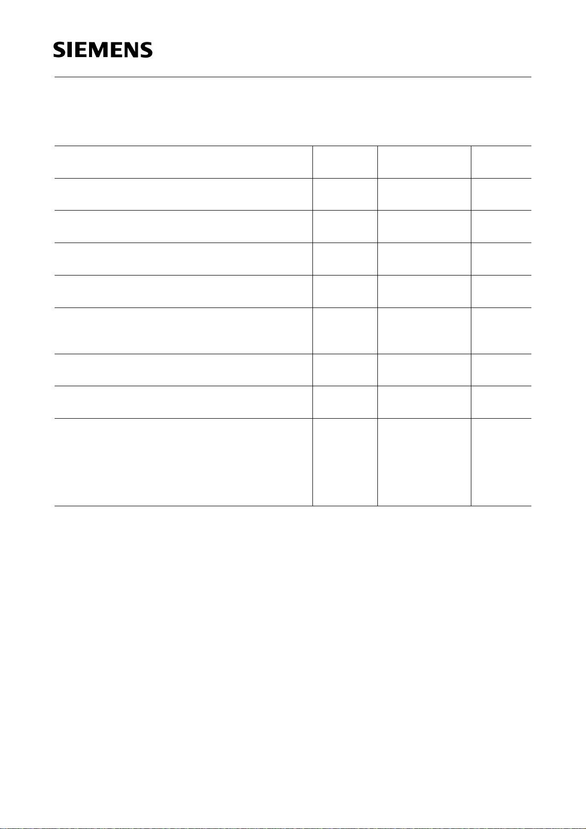
Grenzwerte
Maximum Ratings
LS A672, LO A672, LY A672
LG A672, LP A672
Bezeichnung
Parameter
Betriebstemperatur
Operating temperature range
Lagertemperatur
Storage temperature range
Sperrschichttemperatur
Junction temperature
Durchlaßstrom
Forward current
Stoßstrom
Surge current
t ≤ 10 µs, D = 0.005
Sperrspannung
Reverse voltage
Verlustleistung
Power dissipation
Wärmewiderstand
Thermal resistance
Sperrschicht / Umgebung
Junction / air
Montage auf PC-board*) (Padgröße je ≥ 16 mm2)
mounted on PC board*) (padsize ≥ 16 mm2 each )
Symbol
Symbol
T
op
T
stg
T
j
I
F
I
FM
V
R
P
tot
R
th JA
Werte
Values
Einheit
Unit
– 55 ... + 100 ˚C
– 55 ... + 100 ˚C
+ 100 ˚C
50 mA
1A
5V
190 mW
330 K/W
)
*
PC-board: FR4
Semiconductor Group 3 1998-11-12
Page 4

Kennwerte (TA = 25 ˚C)
Characteristics
LS A672, LO A672, LY A672
LG A672, LP A672
Bezeichnung
Parameter
Wellenlänge des emittierten Lichtes (typ.)
Wavelength at peak emission (typ.)
I
= 10 mA
F
Dominantwellenlänge (typ.)
Dominant wavelength (typ.)
I
= 10 mA
F
Spektrale Bandbreite bei 50 % I
Spectral bandwidth at 50 % I
I
= 10 mA
F
rel max
rel max
(typ.)
(typ.)
Abstrahlwinkel bei 50 % Iv (Vollwinkel)
Viewing angle at 50 % I
v
Durchlaßspannung (typ.)
Forward voltage (max.)
I
= 50 mA
F
Sperrstrom (typ.)
Reverse current (max.)
V
= 5 V
R
Kapazität (typ.)
Capacitance
V
= 0 V, f = 1 MHz
R
Schaltzeiten:
Switching times:
I
from 10 % to 90 % (typ.)
V
I
from 90 % to 10 % (typ.)
V
I
= 100mA, tp = 10 µs, RL= 50 Ω
F
Symbol
Symbol
Werte
Values
Einheit
Unit
LS LO LY LG LP
λ
λ
peak
dom
635 610 586 565 557 nm
628 605 590 570 560 nm
∆λ 45 40 45 25 22 nm
2ϕ 120 120 120 120 120 deg.
V
V
I
I
C
t
t
F
F
R
R
0
r
f
2.0
3.8
2.1
3.8
2.2
3.8
2.6
3.8
2.6
3.8*
V
)
V
0.01100.01100.01100.01100.0110µA
µA
40 35 35 60 80 pF
350
200
500
250
350
200
500
250
500
250nsns
)
V
max = 3.2 V as of Febr. 97
*
F
Semiconductor Group 4 1998-11-12
Page 5

LS A672, LO A672, LY A672
LG A672, LP A672
Relative spektrale Emission I
= f (λ), TA = 25 ˚C, IF= 10 mA
rel
Relative Spectral Emission
V (λ) = spektrale Augenempfindlichkeit
Standard eye response curve
100
%
Ι
rel
80
60
40
blue
20
OHL01698
V
λ
red
orange
green
yellow
pure-green
super-red
hyper-red
0
400 450 500 550 600 650 700
Abstrahlcharakteristik I
Radiation characteristic
50˚
60˚
70˚
80˚
= f (ϕ)
rel
nm
λ
0˚10˚20˚40˚ 30˚
ϕ
1.0
OHL01660
0.8
0.6
0.4
0.2
90˚
0
100˚
1.0 0.8 0.6 0.4
0˚ 20˚ 40˚ 60˚ 80˚ 100˚ 120˚
Semiconductor Group 5 1998-11-12
Page 6

LS A672, LO A672, LY A672
LG A672, LP A672
Durchlaßstrom IF = f (VF)
Forward current
T
= 25 ˚C
A
Relative Lichtstärke IV/I
V(50 mA)
Relative luminous intensity
T
= 25 ˚C
A
= f (IF)
Zulässige Impulsbelastbarkeit IF = f (tp)
Permissible pulse handling capability
Duty cycle D = parameter,TA = 25 ˚C
Maximal zulässiger Durchlaßstrom
Max. permissible forward current
I
= f (TA)
F
Semiconductor Group 6 1998-11-12
Page 7

LS A672, LO A672, LY A672
LG A672, LP A672
Wellenlänge der Strahlung λ
Wavelength at peak emission
I
= 10 mA
F
690
λ
peak
nm
650
super-red
630
610
590
570
550
0 20 40 60 80 100
orange
yellow
green
pure-green
= f (TA)
peak
OHL02104
˚C
Dominantwellenlänge λ
Dominat wavelength
I
= 10 mA
F
690
λ
dom
nm
650
630
610
590
570
550
0 20 40 60 80 100
super-red
orange
yellow
green
pure-green
= f (TA)
dom
OHL02105
˚C
Durchlaßspannung VF = f (TA)
Forward voltage
I
= 50 mA
F
T
Relative Lichtstärke IV / I
V(25 ˚C)
= f (TA)
T
Relative luminous intensity
I
= 50 mA
F
Semiconductor Group 7 1998-11-12
Page 8

LS A672, LO A672, LY A672
Maßzeichnung (Maße in mm, wenn nicht anders angegeben)
Package Outlines (Dimensions in mm, unless otherwise specified)
(2.4)
4.2
3.8
2.8
2.4
0.7
LG A672, LP A672
2.54
Cathode
Cathode marking
(2.9)
spacing
(1.4)
(R1)
4.2
3.8
Kathodenkennung: abgeschrägte Ecke
Cathode mark: bevelled edge
1.1
0.9
Anode
(0.3)
3.8
(2.85)
3.4
GPL06880
Semiconductor Group 8 1998-11-12
 Loading...