

Page 1
HD74LS273
Octal D-type Positive-edge-triggered Flip-Flops (with Clear)
REJ03D0473–0300
Rev.3.00
Jul.15.2005
The HD74LS273, positive-edge-triggered flip-flops utilize LS TTL circuitry to implement D-type flip-flop logic with a
direct clear input.
Information at the D inputs meeting the setup time requirements is transferred to the Q outputs on the positive-going
edge of the clock pulse.
When the clock input is at either the high or low level, the D input signal has no effect at the output.
Features
• Ordering Information
Part Name Package Type
HD74LS273P DILP-20 pin
HD74LS273FPEL SOP-20 pin (JEITA)
HD74LS273RPEL SOP-20 pin (JEDEC)
Note: Please consult the sales office for the above package availability.
Package Code
(Previous Code)
PRDP0020AC-B
(DP-20NEV)
PRSP0020DD-B
(FP-20DAV)
PRSP0020DC-A
(FP-20DBV)
Package
Abbreviation
P —
FP EL (2,000 pcs/reel)
RP EL (1,000 pcs/reel)
Taping Abbreviation
(Quantity)
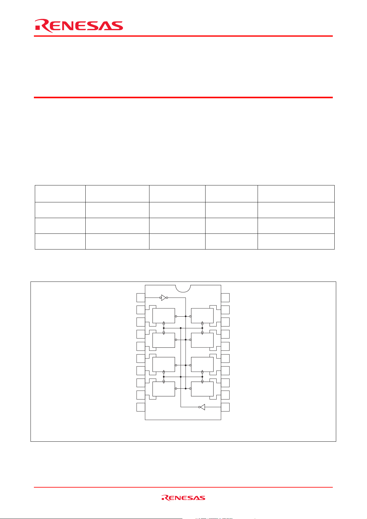
Pin Arrangement
Clear
1Q
1D
2D
2Q
3Q
3D
4D
4Q
GND
1
2
Q
Clear
DCK
3
4
DCK
Clear
Q
5
6
Q
Clear
DCK
7
8
DCK
Clear
Q
9
10 11
(Top view)
Clear
Clear
Clear
Clear
20
19
Q
DCK
18
17
DCK
Q
16
15
Q
DCK
14
13
DCK
Q
12
V
CC
8Q
8D
7D
7Q
6Q
6D
5D
5Q
Clock
Rev.3.00, Jul.15.2005, page 1 of 6
Page 2
HD74LS273
Function Table
Inputs Output
Clear Clock D Q
L X X L
H ↑ H H
H ↑ L L
H L X Q0
Notes: H; high level, L; low level, X; irrelevant
↑; transition from low to high level
Q0; level of Q before the indicated steady-state input conditions were established.
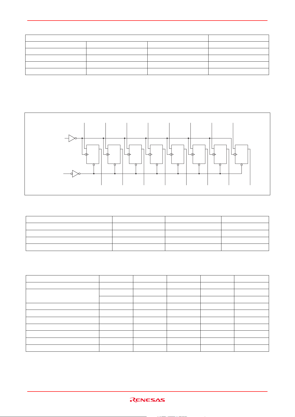
Block Diagram
1D 2D 3D 4D 5D 6D 7D
8D
Clock (1)
D
CK
Clear
D
Q
CK
Clear
D
Q
CK
Clear
D
Q
CK
Clear
D
Q
CK
Clear
D
Q
CK
Clear
D
Q
CK
Clear
D
Q
Q
CK
Clear
Clear (2)
1Q 2Q 3Q 4Q 5Q 6Q 7Q 8Q
Absolute Maximum Ratings
Item Symbol Ratings Unit
Supply voltage VCC 7 V
Input voltage VIN 7 V
Power dissipation PT 400 mW
Storage temperature Tstg –65 to +150 °C
Note: Voltage value, unless otherwise noted, are with respect to network ground terminal.
Recommended Operating Conditions
Item Symbol Min Typ Max Unit
Supply voltage VCC 4.75 5.00 5.25 V
Output current
Operating temperature Topr –20 25 75 °C
Clock frequency ƒ
Clock pulse width t
Clear pulse width t
Data setup time t
Clear (inactive-state) setup time t
Data hold time t
Rev.3.00, Jul.15.2005, page 2 of 6
IOH — — –400 µA
I
— — 8 mA
OL
0 — 30 MHz
clock
20 — — ns
w (clock)
20 — — ns
w (clear)
20↑ — — ns
su (data)
25↑ — — ns
su (clear)
5↑ — — ns
h (data)
Page 3
HD74LS273
Electrical Characteristics
(Ta = –20 to +75 °C)
Item Symbol min. typ.* max. Unit Condition
Input voltage
Output voltage
Input current
Short-circuit output current IOS –20 — –100 mA VCC = 5.25 V
Supply current ICC** — 17 27 mA VCC = 5.25 V
Input clamp voltage VIK — — –1.5 V VCC = 4.75 V, IIN = –18 mA
Notes: * VCC = 5 V, Ta = 25°C
** With all outputs open and 4.5 V applied to all data and clear inputs, I
ground, then 4.5 V is applied to clock.
VIH 2.0 — — V
VIL — — 0.8 V
VOH 2.7 — — V
V
OL
— — 0.5 IOL = 8 mA
— — 0.4
VCC = 4.75 V, VIH = 2 V, VIL = 0.8 V,
= –400 µA
I
OH
V
IOL = 4 mA
VCC = 4.75 V, VIH = 2 V,
= 0.8 V
V
IL
IIH — 20 µA VCC = 5.25 V, VI = 2.7 V
IIL — –0.4 mA VCC = 5.25 V, VI = 0.4 V
— 0.1 mA VCC = 5.25 V, VI = 7 V
I
I
is measured after a momentary
CC
Switching Characteristics
Item Symbol Inputs min. typ. max. Unit Condition
Maximum clock frequency ƒ
Propagation delay time
Clock 30 40 — MHz
max
t
Clear — 18 27
PHL
t
— 17 27
t
PLH
PHL
Clock
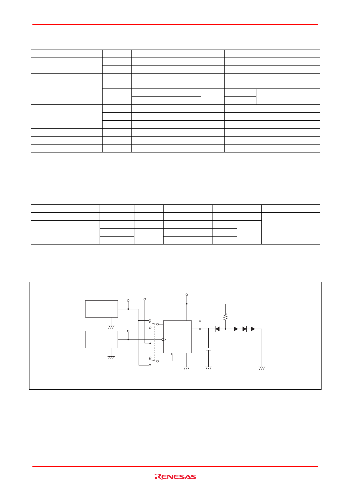
Testing Method
Test Circuit
4.5V
Input
P.G.
Z
out
= 50Ω
Input
P.G.
Z
out
= 50Ω
Notes: 1. CL includes probe and jig capacitance.
2. All diodes are 1S2074(H).
D
Clock
Clear
— 18 27
V
CC
Output
R
L
Q
C
L
(VCC = 5 V, Ta = 25°C)
ns
CL = 15 pF, RL = 2 kΩ
Rev.3.00, Jul.15.2005, page 3 of 6
Page 4
HD74LS273
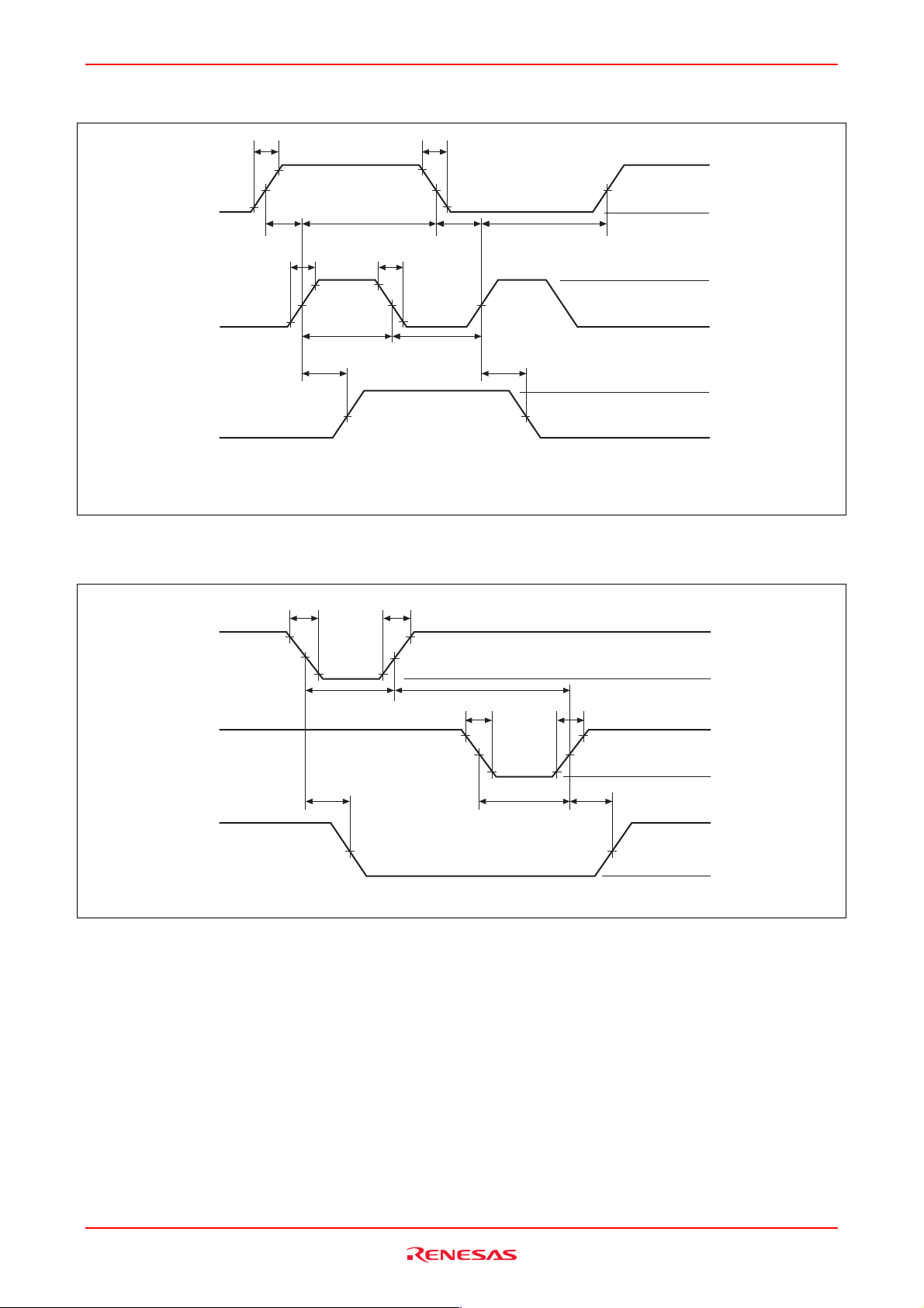
Waveforms 1
Data
Clock
Q
Notes: Input pulse; t
Clock input; PRR = 1 MHz, duty cycle 50%
Data input; PRR = 500 kHz, duty cycle 50%
Waveforms 2
10%
TLH
t
TLH
90%
1.3 V
t
su
t
TLH
10%
≤ 15 ns, t
90%
1.3 V
t
PLH
THL
t
h
90%
1.3 V
t
w
1.3 V
≤ 6 ns,
t
THL
90%
1.3 V 1.3 V
t
THL
10%
10%
t
su
1.3 V
t
w
t
PHL
t
h
1.3 V
3V
0V
3V
0V
V
V
OH
OL
Clear
Clock
Q
Note: Input pulse: t
t
THL
t
90% 90%
1.3V 1.3V
10%
t
w
t
PHL
1.3V
≤ 15 ns, t
TLH
≤ 6 ns, PRR = 1 MHz.
THL
TLH
10%
t
w
t
THL
90% 90%
1.3V 1.3V
10%
t
w
t
10%
t
PLH
TLH
1.3V
3V
0V
3V
0V
V
V
OH
OL
Rev.3.00, Jul.15.2005, page 4 of 6
Page 5
HD74LS273
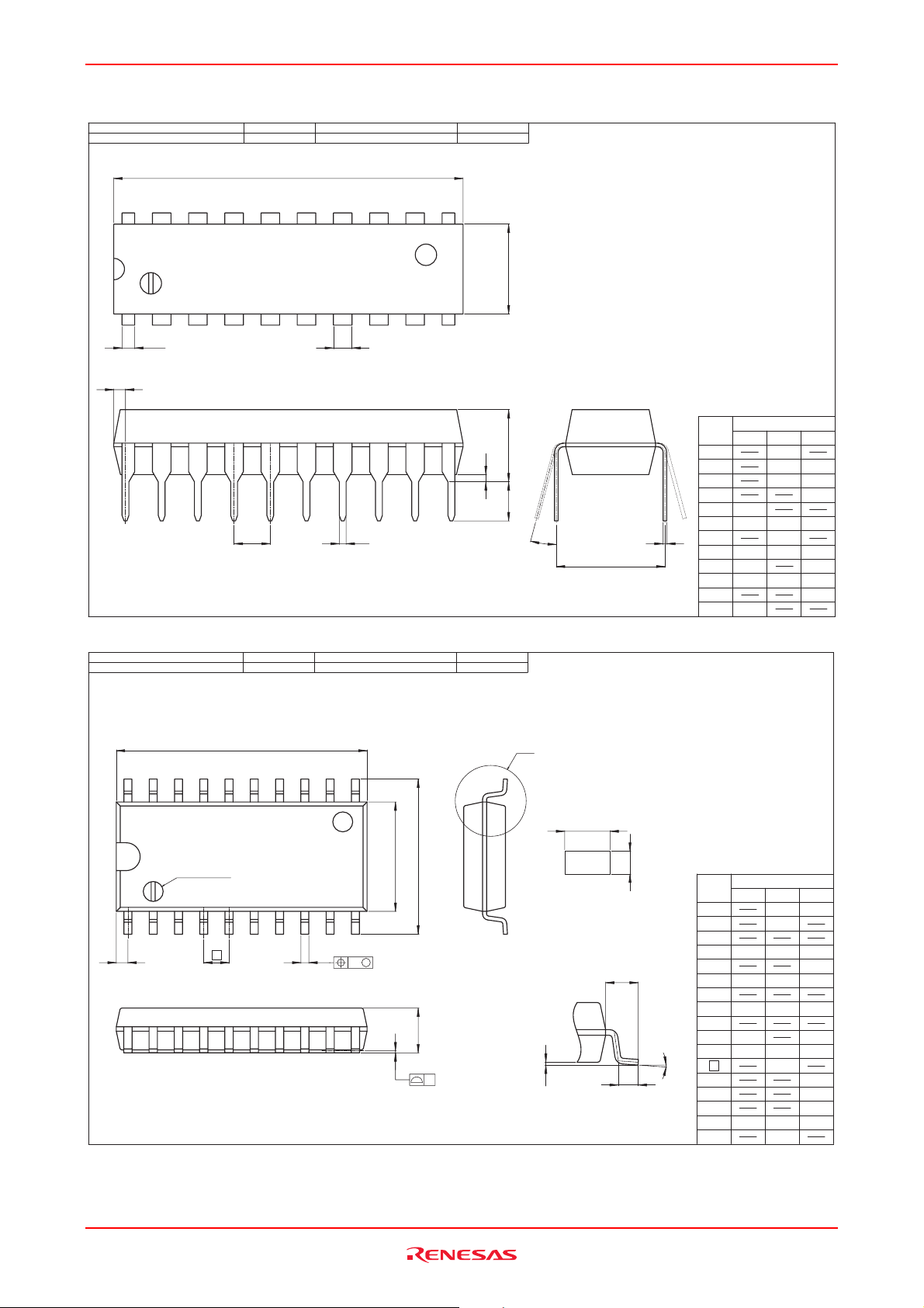
Package Dimensions
RENESAS CodeJEITA Package Code Previous Code
PRDP0020AC-BP-DIP20-6.3x24.5-2.54
D
20 11
DP-20NEV
MASS[Typ.]
1.26g
E
1 10
0.89
Z
e c
b
3
b
P-SOP20-5.5x12.6-1.27 PRSP0020DD-B
20 11
RENESAS CodeJEITA Package Code Previous Code
*1
D
p
FP-20DAV
1
A
MASS[Typ.]
0.31g
Dimension in Millimeters
Reference
A
L
θ
e
1
( Ni/Pd/Au plating )
NOTE)
1. DIMENSIONS"*1 (Nom)"AND"*2"
F
DO NOT INCLUDE MOLD FLASH.
2. DIMENSION"*3"DOES NOT
INCLUDE TRIM OFFSET.
Symbol
e
1
D
E
A
A
0.51
1
0.40 0.48
b
p
b
3
0.19 0.25 0.31
c
θ
e
2.29 2.54 2.79
Z
L
2.54
°
0
7.62
24.50
6.30
1.30
MaxNomMin
25.40
7.00
5.08
0.56
15
1.27
°
Index mark
1
Z
e
Rev.3.00, Jul.15.2005, page 5 of 6
b
p
E
H
E
*2
Terminal cross section
( Ni/Pd/Au plating )
10
*3
b
p
Mx
A
y
1
A
Detail F
c
Dimension in Millimeters
Reference
Symbol
D
E
A
2
A
1
L
1
L
A
b
p
b
1
c
c
1
0
°
θ
H
7.50 8.00
E
e
θ
x
y
Z
L
L
1
12.60
5.50
0.400.34
7.80
1.27
1.15
MaxNomMin
13.0
0.200.100.00
2.20
0.46
0.250.200.15
0.12
0.15
0.80
0.900.700.50
8
°
Page 6
HD74LS273
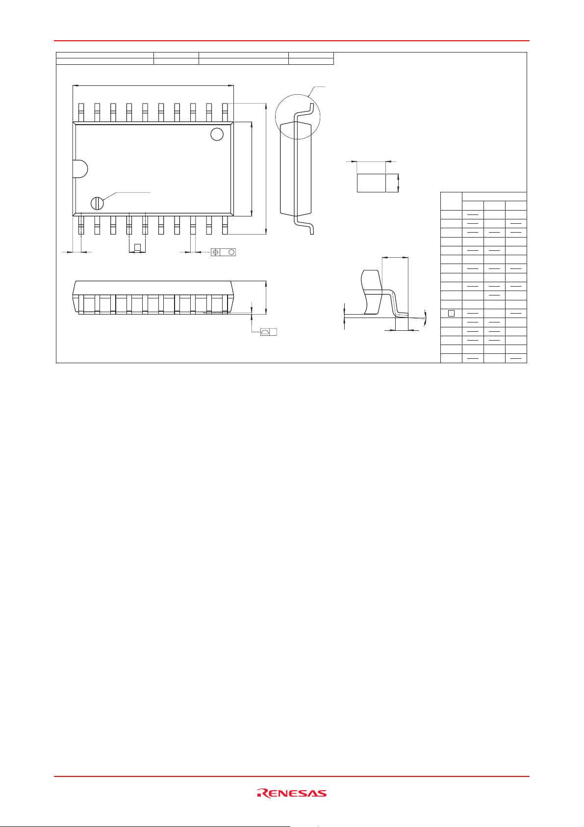
P-SOP20-7.5x12.8-1.27 PRSP0020DC-A
Index mark
1
Z
e
RENESAS CodeJEITA Package Code Previous Code
*1
D
*3
b
p
1120
10
FP-20DBV
Mx
MASS[Typ.]
0.52g
F
NOTE)
1. DIMENSIONS"*1 (Nom)"AND"*2"
@ DO NOT INCLUDE MOLD FLASH.
2. DIMENSION"*3"DOES NOT
@ INCLUDE TRIM OFFSET.
b
Detail F
p
c
Dimension in Millimeters
Reference
Symbol
D
E
A
2
A
1
L
1
L
A
b
p
b
1
c
c
1
0
°
θ
10.00 10.65
H
E
e
θ
x
y
Z
L
L
1
12.80
7.50
0.400.34
10.40
1.27
1.45
MaxNomMin
13.2
0.300.200.10
2.65
0.46
0.300.250.20
8
0.12
0.15
0.935
1.270.700.40
°
E
E
H
*2
Terminal cross section
( Ni/Pd/Au plating )
A
1
y
A
Rev.3.00, Jul.15.2005, page 6 of 6
Page 7
Sales Strategic Planning Div. Nippon Bldg., 2-6-2, Ohte-machi, Chiyoda-ku, Tokyo 100-0004, Japan
Keep safety first in your circuit designs!
1. Renesas Technology Corp. puts the maximum effort into making semiconductor products better and more reliable, but there is always the possibility that trouble
may occur with them. Trouble with semiconductors may lead to personal injury, fire or property damage.
Remember to give due consideration to safety when making your circuit designs, with appropriate measures such as (i) placement of substitutive, auxiliary
circuits, (ii) use of nonflammable material or (iii) prevention against any malfunction or mishap.
Notes regarding these materials
1. These materials are intended as a reference to assist our customers in the selection of the Renesas Technology Corp. product best suited to the customer's
application; they do not convey any license under any intellectual property rights, or any other rights, belonging to Renesas Technology Corp. or a third party.
2. Renesas Technology Corp. assumes no responsibility for any damage, or infringement of any third-party's rights, originating in the use of any product data,
diagrams, charts, programs, algorithms, or circuit application examples contained in these materials.
3. All information contained in these materials, including product data, diagrams, charts, programs and algorithms represents information on products at the time of
publication of these materials, and are subject to change by Renesas Technology Corp. without notice due to product improvements or other reasons. It is
therefore recommended that customers contact Renesas Technology Corp. or an authorized Renesas Technology Corp. product distributor for the latest product
information before purchasing a product listed herein.
The information described here may contain technical inaccuracies or typographical errors.
Renesas Technology Corp. assumes no responsibility for any damage, liability, or other loss rising from these inaccuracies or errors.
Please also pay attention to information published by Renesas Technology Corp. by various means, including the Renesas Technology Corp. Semiconductor
home page (http://www.renesas.com).
4. When using any or all of the information contained in these materials, including product data, diagrams, charts, programs, and algorithms, please be sure to
evaluate all information as a total system before making a final decision on the applicability of the information and products. Renesas Technology Corp. assumes
no responsibility for any damage, liability or other loss resulting from the information contained herein.
5. Renesas Technology Corp. semiconductors are not designed or manufactured for use in a device or system that is used under circumstances in which human life
is potentially at stake. Please contact Renesas Technology Corp. or an authorized Renesas Technology Corp. product distributor when considering the use of a
product contained herein for any specific purposes, such as apparatus or systems for transportation, vehicular, medical, aerospace, nuclear, or undersea repeater
use.
6. The prior written approval of Renesas Technology Corp. is necessary to reprint or reproduce in whole or in part these materials.
7. If these products or technologies are subject to the Japanese export control restrictions, they must be exported under a license from the Japanese government and
cannot be imported into a country other than the approved destination.
Any diversion or reexport contrary to the export control laws and regulations of Japan and/or the country of destination is prohibited.
8. Please contact Renesas Technology Corp. for further details on these materials or the products contained therein.
RENESAS SALES OFFICES
http://www.renesas.com
Refer to "http://www.renesas.com/en/network" for the latest and detailed information.
Renesas Technology America, Inc.
450 Holger Way, San Jose, CA 95134-1368, U.S.A
Tel: <1> (408) 382-7500, Fax: <1> (408) 382-7501
Renesas Technology Europe Limited
Dukes Meadow, Millboard Road, Bourne End, Buckinghamshire, SL8 5FH, U.K.
Tel: <44> (1628) 585-100, Fax: <44> (1628) 585-900
Renesas Technology Hong Kong Ltd.
7th Floor, North Tower, World Finance Centre, Harbour City, 1 Canton Road, Tsimshatsui, Kowloon, Hong Kong
Tel: <852> 2265-6688, Fax: <852> 2730-6071
Renesas Technology Taiwan Co., Ltd.
10th Floor, No.99, Fushing North Road, Taipei, Taiwan
Tel: <886> (2) 2715-2888, Fax: <886> (2) 2713-2999
Renesas Technology (Shanghai) Co., Ltd.
Unit2607 Ruijing Building, No.205 Maoming Road (S), Shanghai 200020, China
Tel: <86> (21) 6472-1001, Fax: <86> (21) 6415-2952
Renesas Technology Singapore Pte. Ltd.
1 Harbour Front Avenue, #06-10, Keppel Bay Tower, Singapore 098632
Tel: <65> 6213-0200, Fax: <65> 6278-8001
Renesas Technology Korea Co., Ltd.
Kukje Center Bldg. 18th Fl., 191, 2-ka, Hangang-ro, Yongsan-ku, Seoul 140-702, Korea
Tel: <82> 2-796-3115, Fax: <82> 2-796-2145
Renesas Technology Malaysia Sdn. Bhd.
Unit 906, Block B, Menara Amcorp, Amcorp Trade Centre, No.18, Jalan Persiaran Barat, 46050 Petaling Jaya, Selangor Darul Ehsan, Malaysia
Tel: <603> 7955-9390, Fax: <603> 7955-9510
© 2005. Renesas Technology Corp., All rights reserved. Printed in Japan.
Colophon .3.0
 Loading...