

Page 1

LR9548S
LR9548S
GPS Module
GPS Module
Page 2

Copyright
©2006 Leadtek Research Inc. All rights reserved. No part of this publication may be reproduced, stored in a retrieval
system, or transmitted in any form or by any means, electronic, mechanical, photocopying, recording or otherwise,
without the prior written consent of Leadtek Research Inc.
Trademarks
Leadtek and the Leadtek logo are registered trademarks of Leadtek Research Inc.
All other trademarks are the property of their respective owners.
Changes
The material in this document is for information only and is subject to change without notice. While reasonable efforts
have been made in the preparation of this document to assure its accuracy, Leadtek Research assumes no liability
resulting from errors or omissions in this document, or from the use of the information contained herein.
Leadtek reserves the right to make changes in the product design without reservation and without notification to its
users.
THE DOCUMENT IS PROVIDED BY LEADTEK "AS IS", AND ANY EXPRESS OR IMPLIED WARRANTIES,
INCLUDING, BUT NOT LIMITED TO, THE IMPLIED WARRANTIES OF MERCHANTABILITY AND
FITNESS FOR A PARTICULAR PURPOSE ARE DISCLAIMED. IN NO EVENT SHALL LEADTEK BE LIABLE
FOR ANY DIRECT, INDIRECT, INCIDENTAL, SPECIAL, EXEMPLARY, OR CONSEQUENTIAL DAMAGES
(INCLUDING, BUT NOT LIMITED TO, PROCUREMENT OF SUBSTITUTE GOODS OR SERVICES; LOSS OF
USE, DATA, OR PROFITS; OR BUSINESS INTERRUPTION) HOWEVER CAUSED AND ON ANY THEORY
OF LIABILITY, WHETHER IN CONTRACT, STRICT LIABILITY, OR TORT (INCLUDING NEGLIGENCE OR
OTHERWISE) ARISING IN ANY WAY OUT OF THE USE OF THIS DOCUMENT, EVEN IF ADVISED OF THE
POSSIBILITY OF SUCH DAMAGE.
Customer Support
Visit our Web site at www.leadtek.com.tw.
For support via e-mail, submit your question at [email protected]
.
Leadtek Research Inc. 18F, 166, Chien-Yi Rd., Chung Ho, Taipei Hsien, Taiwan (235)
Telephone: +886-(0)2 8226 5800
Fax: +886-(0)2 8226 3087
Leadtek Research USA 910 Auburn Ct. Fremont, CA 94538, USA
Telephone: +510 490 8076
Fax: +510 490 7759
Page 3

Contents
FEATURES.....................................................................................................................................1
ARDWARE AND SOFTWARE .........................................................................................................1
H
ERFORMANCE ..............................................................................................................................2
P
NTERFACE ....................................................................................................................................2
I
ADVANTAGES..............................................................................................................................2
SPECIFICATIONS........................................................................................................................3
ECHNICAL SPECIFICATIONS .........................................................................................................3
T
NVIRONMENTAL CHARACTERISTICS............................................................................................4
E
HYSICAL CHARACTERISTICS ........................................................................................................4
P
NTERFACE SPECIFICATIONS ..........................................................................................................4
I
EFERENCE DESIGN ......................................................................................................................5
R
OFTWARE ....................................................................................................................................6
S
ELECTRICAL SPECIFICATIONS.............................................................................................7
B
LOCK DIAGRAM ..........................................................................................................................7
INTERFACE SPECIFICATION..................................................................................................7
P
HOTOS AND PIN POSITIONS..........................................................................................................7
IN SETTINGS ................................................................................................................................8
P
MECHANICAL DIMENSIONS................................................... ... .............................................9
O
UTLINE DRAWING .......................................................................................................................9
(Bottom view) .........................................................................................................................10
RECOMMENDED FOOTPRINT..............................................................................................11
AUTOMATED MANUFACTURING COMPONENTS ..........................................................12
EEL TAPING SPECIFICATION......................................................................................................12
R
Tape Reel Drawing.............................................................. .................................. .................12
Polystyrene Alloy Taping Specifications............................................................................... .13
Polystyrene Alloy Taping Drawing..................................................................................... .. .13
REFLOW PROFILE...................................................................................................................14
ROHS COMPLIANCE................................................................................................................15
ORDERING INFORMATION...................................................................................................15
ORDERING INFORMATION...................................................................................................16
GLOSSARY..................................................................................................................................17
i
Page 4

y
LR9548S GPS Module Technical Manual v1.52
Introduction
The Leadtek LR9548S GPS module is a high sensitivity, low power, Surface Mount Device (SMD).
This 20-channel global positioning system (GPS) receiver is designed for a wide range of OEM
applications and is based on the GPS signal search capabilities of the SiRFstarIII™ single chip
architecture, SiRF’s newest chipset technology. The LR9548S is also pin-to-pin compatible with the
LR9805-III (LR9548) for easier and faster transition.
The LR9548S is designed to allow quick and easy integration into GPS-related applications such as:
PDA, Pocket PC, and other computing devices
Car and Marine Navigation
Fleet Management /Asset Tracking
AVL and Location-Based Services
Hand-Held Device for Personal Positioning and Navigation
Features
Hardware and Software
Based on the high performance features of the SiRFstarIII single chip
Compact module size for easy integration: 24x20x2.9 mm (0.94x0.79x0.11 in).
Fully automatic assembly: reflow solder assembly ready
Hardware compatible with SiRF GSW3.2.0 software
Multiple I/O pins reserved for customizing special user applications
RoHS compliance
© 2006 Leadtek Research Inc. All rights reserved. Page 1/20
Preliminar
Confidential - Information is subject to change without prior notice.
Page 5

y
LR9548S GPS Module Technical Manual v1.52
Performance
Cold/Warm/Hot Start Time: 42/38/1 sec. at open sky and stationary environments.
Reacquisition Time: 0.1 second
RF Metal Shield for best performance in noisy environments
Multi-path Mitigation Hardware
Interface
TTL level serial port for GPS communications interface
Protocol: NMEA-0183/SiRF Binary (default NMEA)
Baud Rate: 4800, 9600, 19200, 38400 or 57600 bps (default 4800)
Advantages
Ideal for high volume mass production(Taping reel package)
Cost saving through elimination of RF and board to board digital connectors
Flexible and cost effective hardware design for different application needs
Secure SMD PCB mounting method
© 2006 Leadtek Research Inc. All rights reserved. Page 2/20
Preliminar
Confidential - Information is subject to change without prior notice.
Page 6

y
LR9548S GPS Module Technical Manual v1.52
Specifications
Technical Specifications
Feature Item Description
Chipset
General
Accuracy
Datum
Time to First Fix
(TTFF)
(Open Sky &
Stationary
Requirements)
Dynamic
Conditions
Power
Serial Port
Time-1PPS
Pulse
GSC3f SiRFstarIII single chip
Frequency L1, 1575.42 MHz
C/A code 1.023 MHz chip rate
Channels 20
Position
Velocity 0.1 meters/second
Time 1 microsecond synchronized to GPS time
Default WGS-84
Other selectable for other Datum
Reacquisition 0.1 sec., average
Snap start 1 sec., average
Hot start 1 sec., average typical TTFF
Warm start 38 sec., average typical TTFF
Cold start 42 sec., average typical TTFF
Altitude 18,000 meters (60,000 feet) max.
Velocity 515 meters/second (1000 knots) max.
Acceleration 4g, max.
Jerk 20 meters/second3, max.
Main power input 3.2 ~ 5.0 VDC input
Power consumption
Supply Current
Backup Power 1.65 ~ 5.0 VDC input.
Electrical interface Two full duplex serial TTL interface.
Protocol messages NMEA-0183@4800 bps (Default)
Level TTL
Pulse duration 1 µs
Time reference At the pulse positive edge.
Measurement
10 meters, 2D RMS
5 meters 2D RMS, WAAS corrected
<5meters(50%), DGPS corrected
≈230 mW (continuous mode)
≈70 mA
Aligned to GPS second, ±1 microsecond
© 2006 Leadtek Research Inc. All rights reserved. Page 3/20
Preliminar
Confidential - Information is subject to change without prior notice.
Page 7

y
LR9548S GPS Module Technical Manual v1.52
Environmental Characteristics
Items Description
Operating temperature range -40 deg. C to +85 deg. C
Storage temperature range -55 deg. C to +100 deg. C
Physical Characteristics
Items Description
Length
Width
Height
Weight 2.5g
24 mm ± 0.1mm (0.94in)
20 mm ± 0.1mm (0.79 in)
2.9 mm ± 0.1mm (0.11 in)
Interface Specifications
Items Description
I/O 28 pin SMD micro package
© 2006 Leadtek Research Inc. All rights reserved. Page 4/20
Preliminar
Confidential - Information is subject to change without prior notice.
Page 8
y
LR9548S GPS Module Technical Manual v1.52
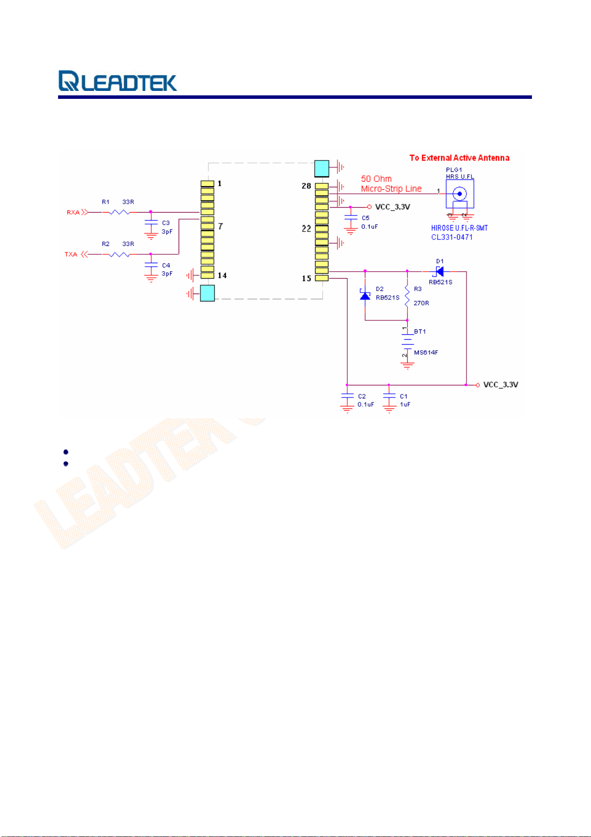
Reference Design
All ground pads attach directly to ground plane by way of via.
All components are reference only.
© 2006 Leadtek Research Inc. All rights reserved. Page 5/20
Preliminar
Confidential - Information is subject to change without prior notice.
Page 9

y
LR9548S GPS Module Technical Manual v1.52
Software
The firmware used on Leadtek LR9548S module is GSW3.2.0, the SiRF standard GPS software for
SiRFstarIII receivers. Features include:
Excellent sensitivity
High configurability
1 Hz position update rate
Supports use of satellite-based augmentation systems like the US WAAS or European EGNOS
system(Option)
Real-time Operating System (RTOS) friendly
Capable of outputting either NMEA(default) or SiRF proprietary binary protocols
Designed to accept custom user tasks executed on the integrated ARM7TDM1 processor(Option)
Runs in full power operation(default) or optional power saving modes
Default configuration is as follows:
Item Description
Core of firmware
Baud rate
Code type
Datum
Protocol message
Output frequency
SiRF GSW3.2.0
4800, 9600, 19200, 38400 or 57600 bps (default 4800)
NMEA-0183 ASCII
WGS-84
GGA(1sec), GSA(5sec), GSV(5sec), RMC(1sec),VTG(1sec)
1 Hz
© 2006 Leadtek Research Inc. All rights reserved. Page 6/20
Preliminar
Confidential - Information is subject to change without prior notice.
Page 10
y
LR9548S GPS Module Technical Manual v1.52
Electrical Specifications
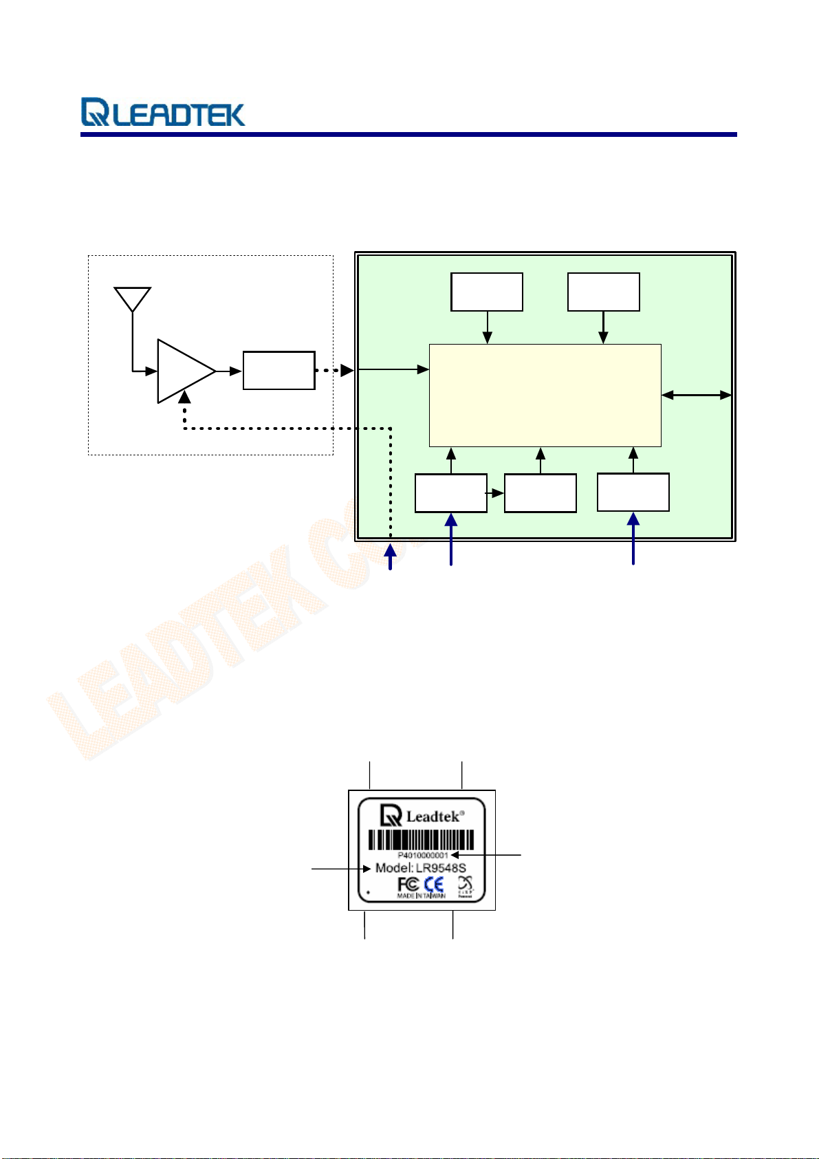
Block Diagram
9548S Block Diagram
Antenna
LNA
bandpass
filter
RFIN
antenna
power
16.369MHz
TCXO
SiRF GSC3f
2.85 VD C
regulator
+ power in + backup battery
voltage
detector
32.768KHz
Crystal
serial
IO
1.50 VDC
regulator
Interface Specification
Photos and Pin Positions
Pin 28
Pin 15
Serial Number
© 2006 Leadtek Research Inc. All rights reserved. Page 7/20
Preliminar
Confidential - Information is subject to change without prior notice.
Model Number
Pin 1
Pin 14
Page 11

y
LR9548S GPS Module Technical Manual v1.52
Pin Settings
PIN Name Type Description
1 FREQ_XFER I If not used, keep floating
2 NC I/O Not connected
3 NC I/O Not connected
4 RXDB I TTL UART Port B input. If not used, keep floating
5 RXDA I TTL UART Port A input
6 TXDA O TTL UART Port A output
7 GPIO5 I/O Reserved, keep floating
8 TIMEMARK I/O 1 PPS output
9 NC I/O Not connected
10 GPIO13 I/O Reserved, keep floating
11 GPIO0 I/O Reserved, keep floating
12 GPIO1 I/O Reserved, keep floating
13 GPIO14 I/O Reserved, keep floating
14 GND PWR Ground
15 VCC_IN PWR 3.2~5.0V DC supply input
16 VSTBY PWR
17 BOOTSEL I Pull high for programming mode. If not used, keep floating
18 PBRESN I Reset pin, active low, If not used, keep floating
19 GPIO15 I/O Reserved, keep floating
20 GND PWR Ground
21 NC I/O Not connected
22 NC I/O Not connected
23 TXDB O TTL UART Port B output. If not used, keep floating
24 NC O Not connected
25 ANTPWR PWR Antenna power input
26 GND PWR Ground
27 RFIN I RF Signal input
28 GND PWR Ground
Apply 1.65~5.0V DC for backup RTC & SRAM. If not used,
keep floating
© 2006 Leadtek Research Inc. All rights reserved. Page 8/20
Preliminar
Confidential - Information is subject to change without prior notice.
Page 12
y
LR9548S GPS Module Technical Manual v1.52
Mechanical Dimensions
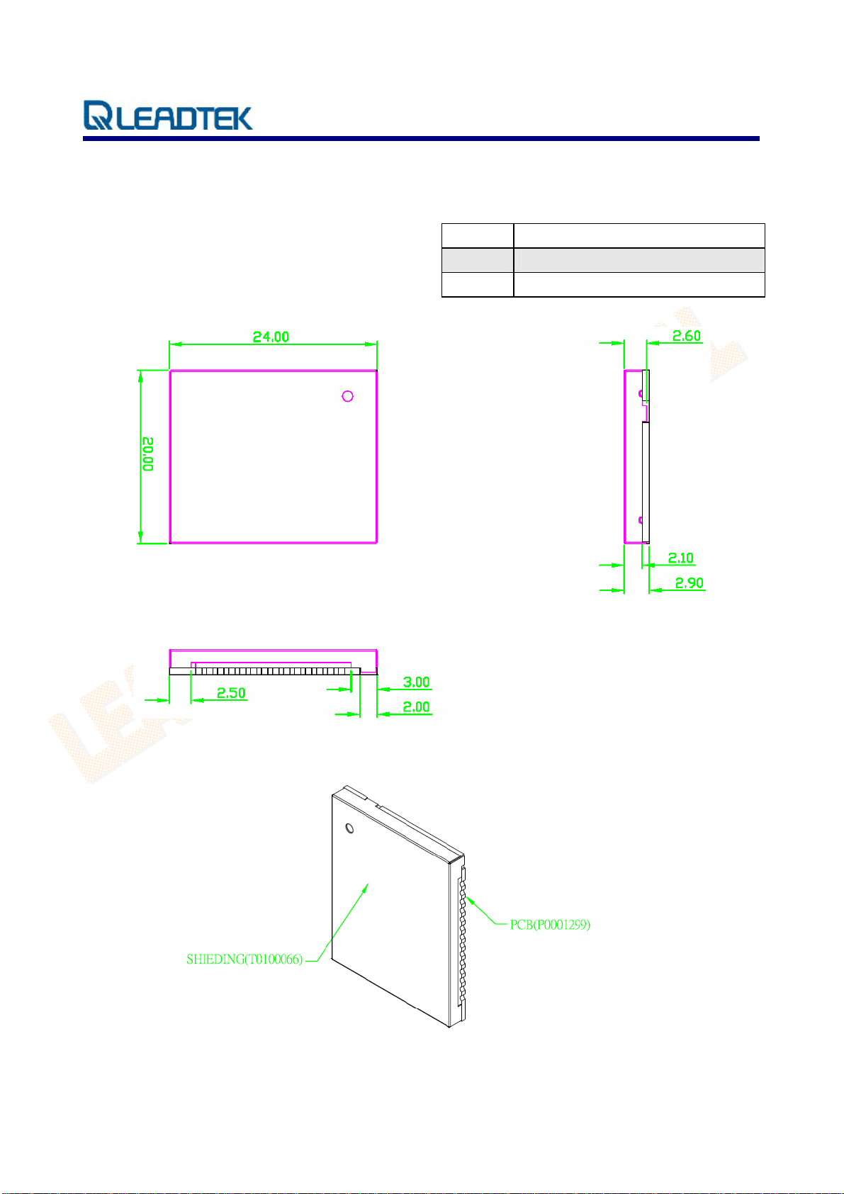
Outline Drawing
Tolerance:
Length 24.0 ± 0.4 mm
Width 20.0 ± 0.1 mm
Height 2.90 ± 0.1 mm
© 2006 Leadtek Research Inc. All rights reserved. Page 9/20
Preliminar
Confidential - Information is subject to change without prior notice.
Page 13
y
LR9548S GPS Module Technical Manual v1.52
(Bottom view)
© 2006 Leadtek Research Inc. All rights reserved. Page 10/20
Preliminar
Confidential - Information is subject to change without prior notice.
Page 14
y
LR9548S GPS Module Technical Manual v1.52
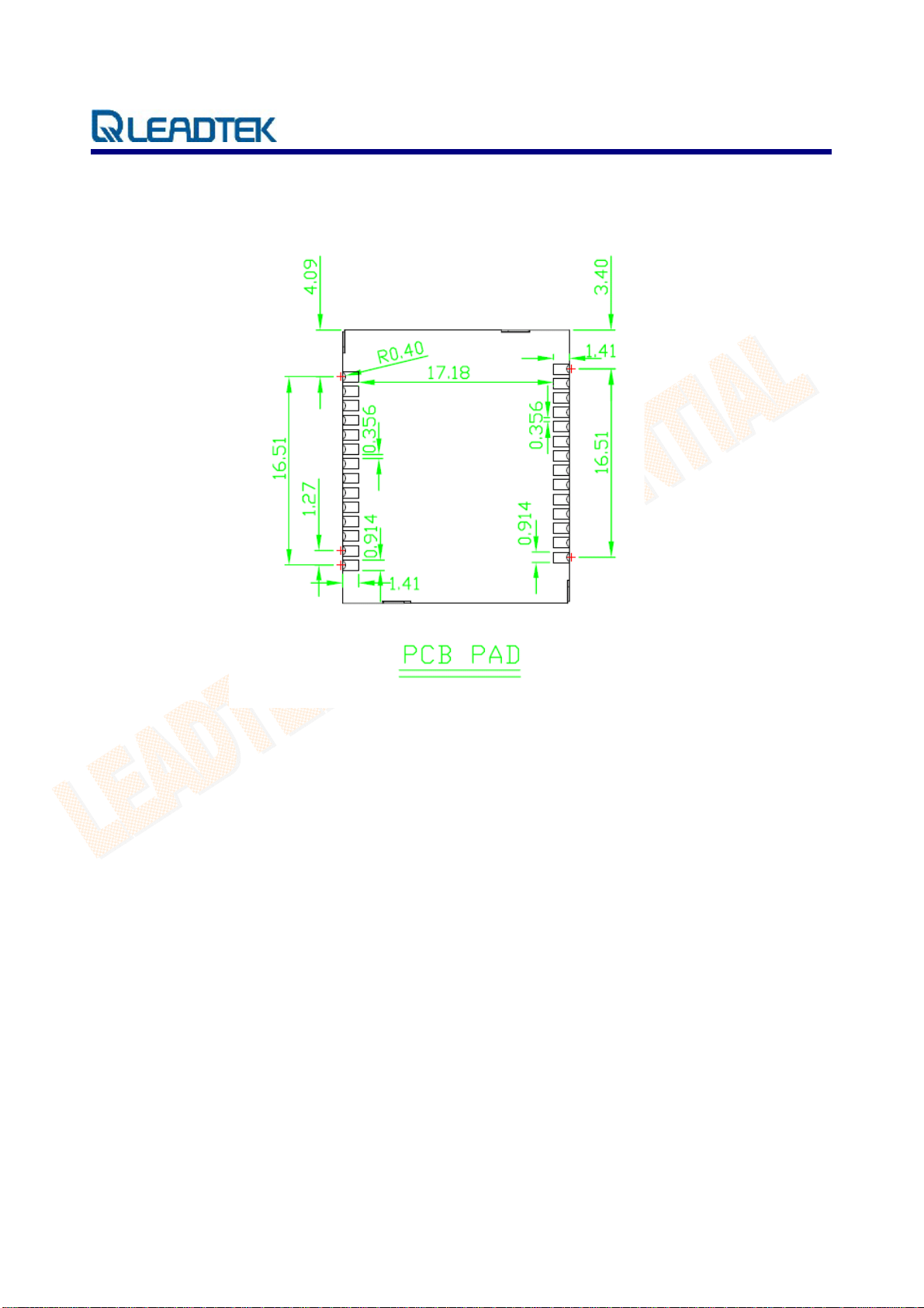
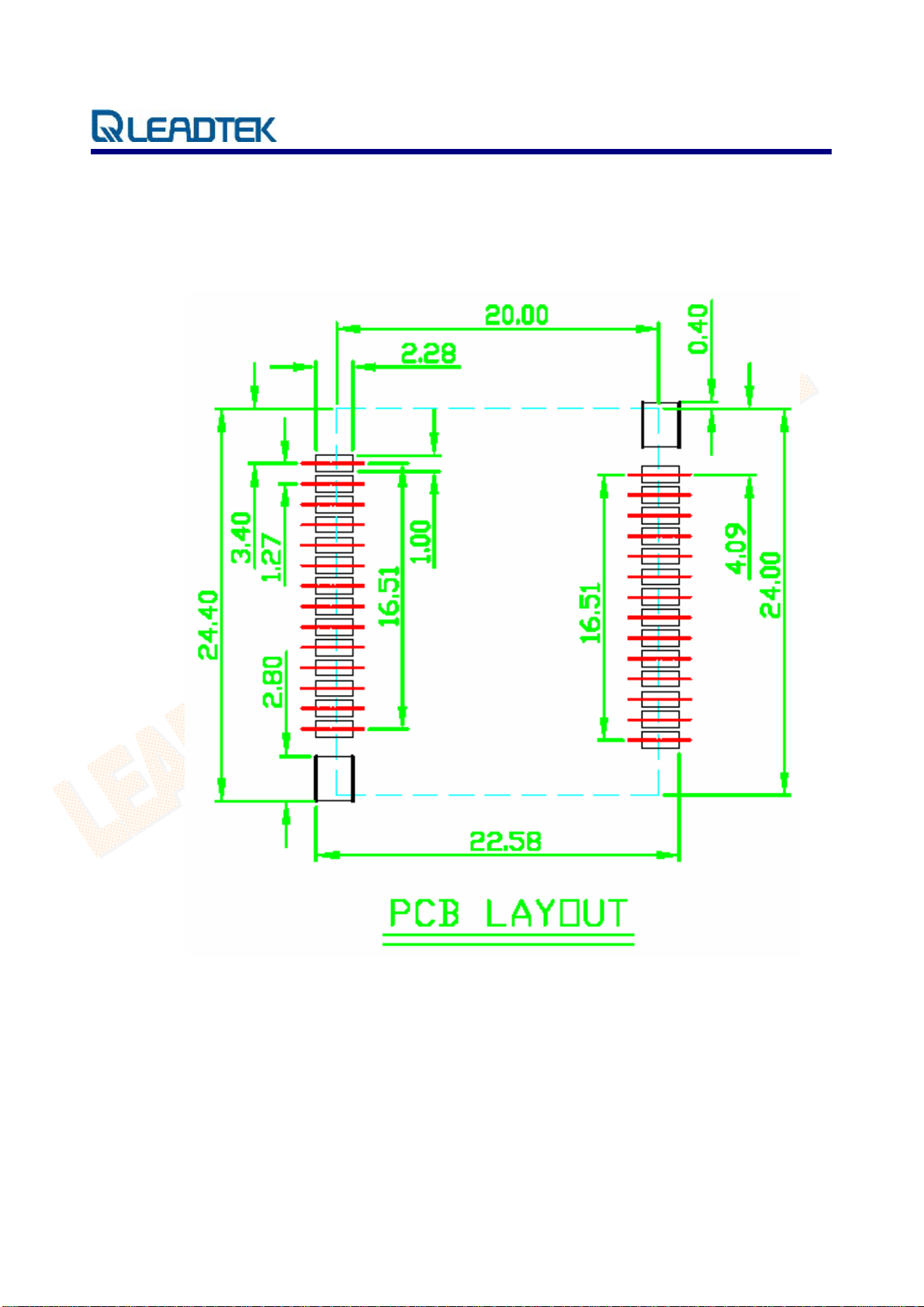
Recommended Footprint
(Unit: mm)
© 2006 Leadtek Research Inc. All rights reserved. Page 11/20
Preliminar
Confidential - Information is subject to change without prior notice.
Page 15
y
LR9548S GPS Module Technical Manual v1.52
Automated Manufacturing Components
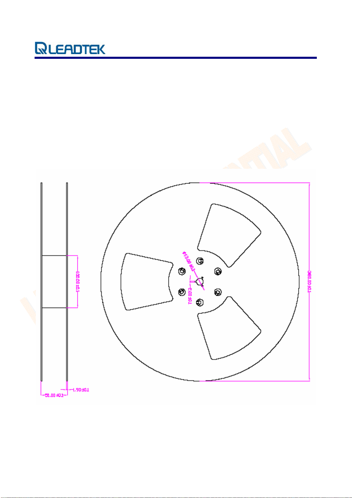
Reel Taping Specification
Material: Black Conductive High Impact Polystyrene Alloy (UP-6100)
Surface resistivity 10
Quantity per reel: 1000 pcs./reel
(Unit: mm)
9
– 1012 Ω/□
Tape Reel Drawing
© 2006 Leadtek Research Inc. All rights reserved. Page 12/20
Preliminar
Confidential - Information is subject to change without prior notice.
Page 16
y
LR9548S GPS Module Technical Manual v1.52
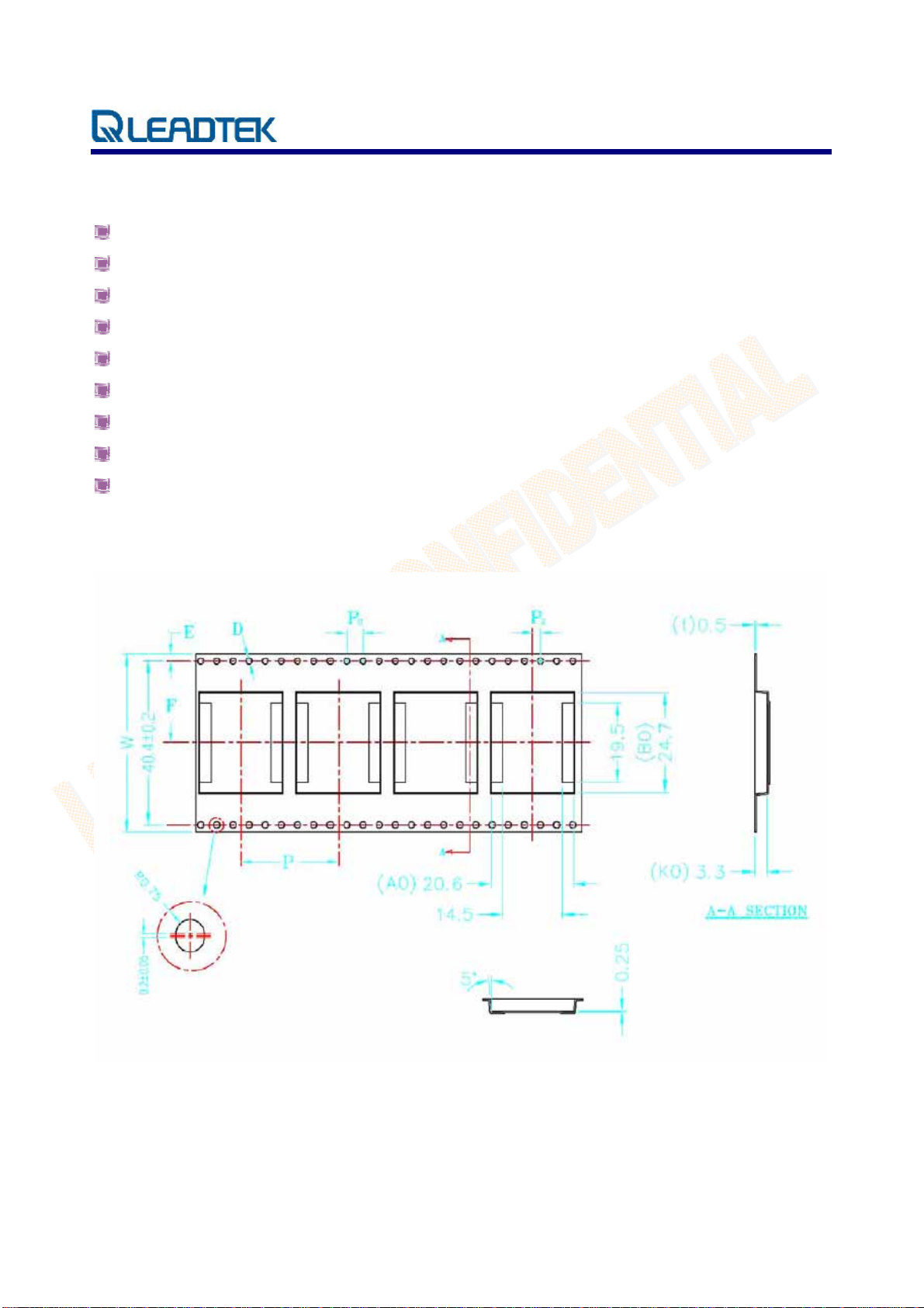
Polystyrene Alloy Taping Specifications
10 sprocket hole pitch cumulative tolerance ±0.20mm
Carrier camber is within 1mm in 250mm
A0 and B0 measured on a plane 0.3mm above the bottom of the pocket
K0 measured from a plane on the inside bottom of the pocket to the top surface of the carrier
Material: black anti-static polystyrene alloy
All dimensions meet EIA-481-3 requirements
Thickness: 0.50±0.05cm
Packing length per 22” reel: 50.0 Meters (1:2)
Component load per 15” reel: 1000 pcs. (SUR-56-3-XL)
Polystyrene Alloy Taping Drawing
© 2006 Leadtek Research Inc. All rights reserved. Page 13/20
Preliminar
Confidential - Information is subject to change without prior notice.
Page 17
y
LR9548S GPS Module Technical Manual v1.52
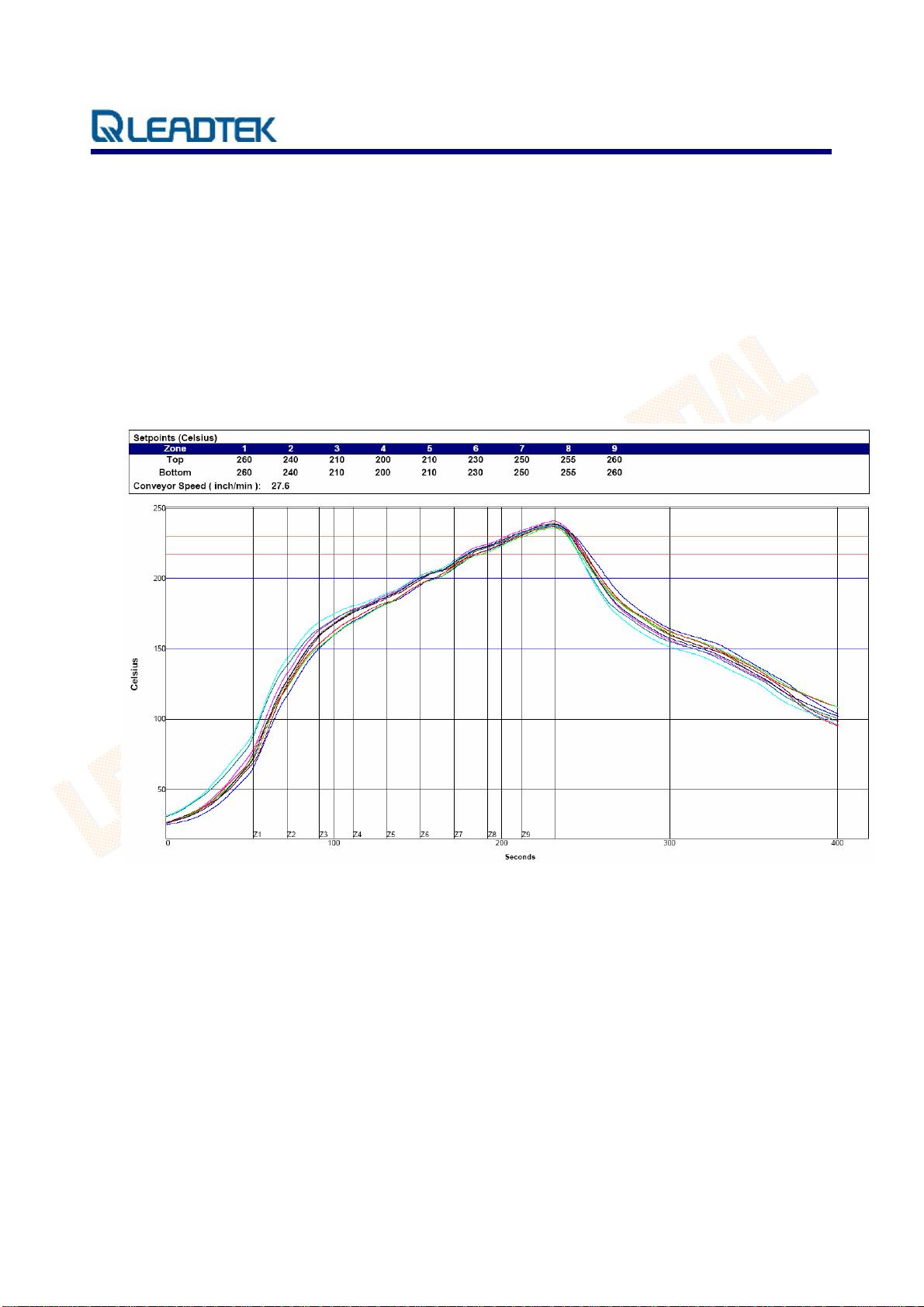
Reflow Profile
High quality, low defect soldering requires identifying the optimum temperature profile for reflowing
the solder paste. To have the correct profile assures components, boards, and solder joints are not
damaged and reliable solder connection is achievable. Profiles are essential for establishing and
maintaining processes. You must be able to repeat the profile to achieve process consistency. The
heating and cooling rise rates must be compatible with the solder paste and components. The amount
of time that the assembly is exposed to certain temperatures must first be defined and then maintained.
The following is an example of a typical thermal profile.
© 2006 Leadtek Research Inc. All rights reserved. Page 14/20
Preliminar
Confidential - Information is subject to change without prior notice.
Page 18
y
LR9548S GPS Module Technical Manual v1.52
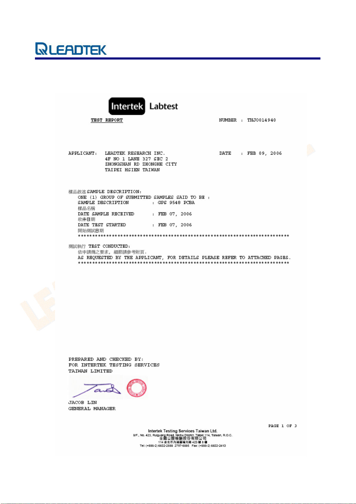
RoHS Compliance
© 2006 Leadtek Research Inc. All rights reserved. Page 15/20
Preliminar
Confidential - Information is subject to change without prior notice.
Page 19

y
LR9548S GPS Module Technical Manual v1.52
Ordering Information
For every order of 1000 pcs , Leadtek will ship the modules with the reel package (shown on page 12).
For order quantities less than 1000 pcs, or when ordering non-whole numbers, Leadtek will snip the
taping and ship the quantity that you request without the reel.
To place an order, contact [email protected]
© 2006 Leadtek Research Inc. All rights reserved. Page 16/20
Preliminar
Confidential - Information is subject to change without prior notice.
Page 20

y
LR9548S GPS Module Technical Manual v1.52
Glossary
A-GPS
Assisted GPS or AGPS is a technology that uses an assistance server to cut down the time needed to
find the location. Although GPS provides excellent position accuracy, position fixes require lines of
sight to the satellites. In regular GPS networks there are only GPS satellites and GPS receivers.
In A-GPS networks, the receiver, being limited in processing power and normally under less than ideal
locations for position fixing, communicates with the assistance server that has high processing power
and access to a reference network. Although dependent on cellular coverage, AGPS processing is
quicker and more efficient than regular GPS.
API
An application programming interface is a set of definitions of the way one piece of computer software
communicates with another. One of the primary purposes of an API is to provide a set of commonly
used functions, such as to draw windows or icons on the screen. Programmers can then take advantage
of the API by making use of its functionality, saving them the task of programming everything from
scratch.
Baud Rate
Is a measure of the signaling rate, which is the number of changes to the transmission media per
second in a modulated signal.
For Example: 250 baud means that 250 signals are transmitted in one second. If each signal carries 4
bits of information then in each second 1000 bits are transmitted. This is abbreviated as 1000 bit/s.
Dead Reckoning
The process of estimating your position by advancing a known position using course, speed, time and
distance to be traveled. It is figuring out where you will be at a certain time if you hold the speed, time
and course you plan to travel.
© 2006 Leadtek Research Inc. All rights reserved. Page 17/20
Preliminar
Confidential - Information is subject to change without prior notice.
Page 21

y
LR9548S GPS Module Technical Manual v1.52
Differential GPS (DGPS)
An extension of the GPS system that uses land-based radio beacons to transmit position corrections to
GPS receivers. DGPS reduces the effect of selective availability, propagation delay, etc. and can
improve position accuracy to better than 10 meters.
EGNOS (European Geostationary Navigation Overlay System)
A satellite navigation system being developed by the European Space Agency, the European
Commission, and EUROCONTROL. It is intended to supplement the GPS and GLONASS systems by
reporting on the reliability and accuracy of the signals. According to specifications, horizontal position
accuracy should be better than 7 meters. In practice, the horizontal position accuracy is at the meter
level. It will consist of three geostationary satellites and a network of ground stations.
Similar service is provided in America by the WAAS system. See WAAS.
LNA (Low Noise Amplifier)
A special type of electronic amplifier or amplifier used in communication systems to amplify very
weak signals captured by an antenna. It is usually located at the antenna and is a key component, which
is placed at the front-end of a receiver system.
Multi-path mitigation
Anticipating errors caused when a satellite signal reaches the GPS receiver antenna by more than one
path. Usually caused by one or more paths being bounced or reflected off of structures near the
antenna and occurs to some extent everywhere. The signal which traverses a longer path will yield a
larger pseudo range estimate and increase the error.
NMEA (National Marine Electronics Association)
An U.S. standards committee that defines data message structure, contents, and protocols to allow the
GPS receiver to communicate with other pieces of electronic equipment.
© 2006 Leadtek Research Inc. All rights reserved. Page 18/20
Preliminar
Confidential - Information is subject to change without prior notice.
Page 22

y
LR9548S GPS Module Technical Manual v1.52
1PPS
Pulse which is generated once per second. GPS and some radio clocks and related timekeeping gear
have a pulse-per-second or PPS signal that is needed for high accuracy time synchronization. The PPS
signal can be connected in either of two ways, either through the data leads of a serial port or through
the modem control leads. Either way requires conversion of the PPS signal,
Most GPS devices emit an RS-232 serial stream with some kind of timestamp format. Many GPS
devices are small realtime systems with the satellite tracking done at high priority, positioning done at
medium priority, and time output done at low priority. The timestamps often have +- 200 ms of jitter
(variance in delay), and output a PPS signal on the exact second.
SMD (Surface Mount Device)
Electronic device components that are mounted directly onto the surface of printed circuit boards
(PCBs). In the industry it has largely replaced the previous construction method of fitting components
with wire leads into holes in the circuit board (also called through-hole technology).
TCXO (Temperature Controlled Crystal Oscillator)
An electronic device that uses the mechanical resonance of a physical crystal to create an electrical
signal with a very precise frequency and can be embedded in integrated circuits. TCXO reduces the
environmental changes of temperature, humidity, and vibration, to keep a stable output frequency.
© 2006 Leadtek Research Inc. All rights reserved. Page 19/20
Preliminar
Confidential - Information is subject to change without prior notice.
Page 23

y
LR9548S GPS Module Technical Manual v1.52
Time To First Fix (TTFF)
The time it takes a GPS receiver to find satellites after you first turn it on, when the GPS receiver has
lost memory, or has been moved over 300 miles from its last location. Standard TTFF Timing consists
of:
Mode Requires Timing
Snap Start Hot + Clock + Sat Pos 3 minutes off
Hot Start Warm + Ephemeris 30 minutes off
Warm Start Position Accuracy
Time Accuracy
Almanac
Cold Start Nothing N/A
Specifications are typical times assuming good satellite visibility and above threshold signal strengths.
WAAS
A system of satellites and ground stations that provide GPS signal corrections for better position
accuracy. A WAAS-capable receiver can give you a position accuracy of better than three meters, 95
percent of the time. (At this time, the system is still in the development stage and is not fully
operational.) WAAS consists of approximately 25 ground reference stations positioned across the
United States that monitor GPS satellite data. Two master stations, located on either coast, collect data
from the reference stations and create a GPS correction message.
<500 KM
<2 hours
<1 year
© 2006 Leadtek Research Inc. All rights reserved. Page 20/20
Preliminar
Confidential - Information is subject to change without prior notice.
Page 24

Leadtek Research Inc.
18F, 166, Chien-Yi Rd.,
Chung Ho, Taipei Hsien,
Taiwan (235)
©2006 Leadtek Research, Inc.
All rights reserved.
Version 1.52
09/26/06
 Loading...