

Page 1
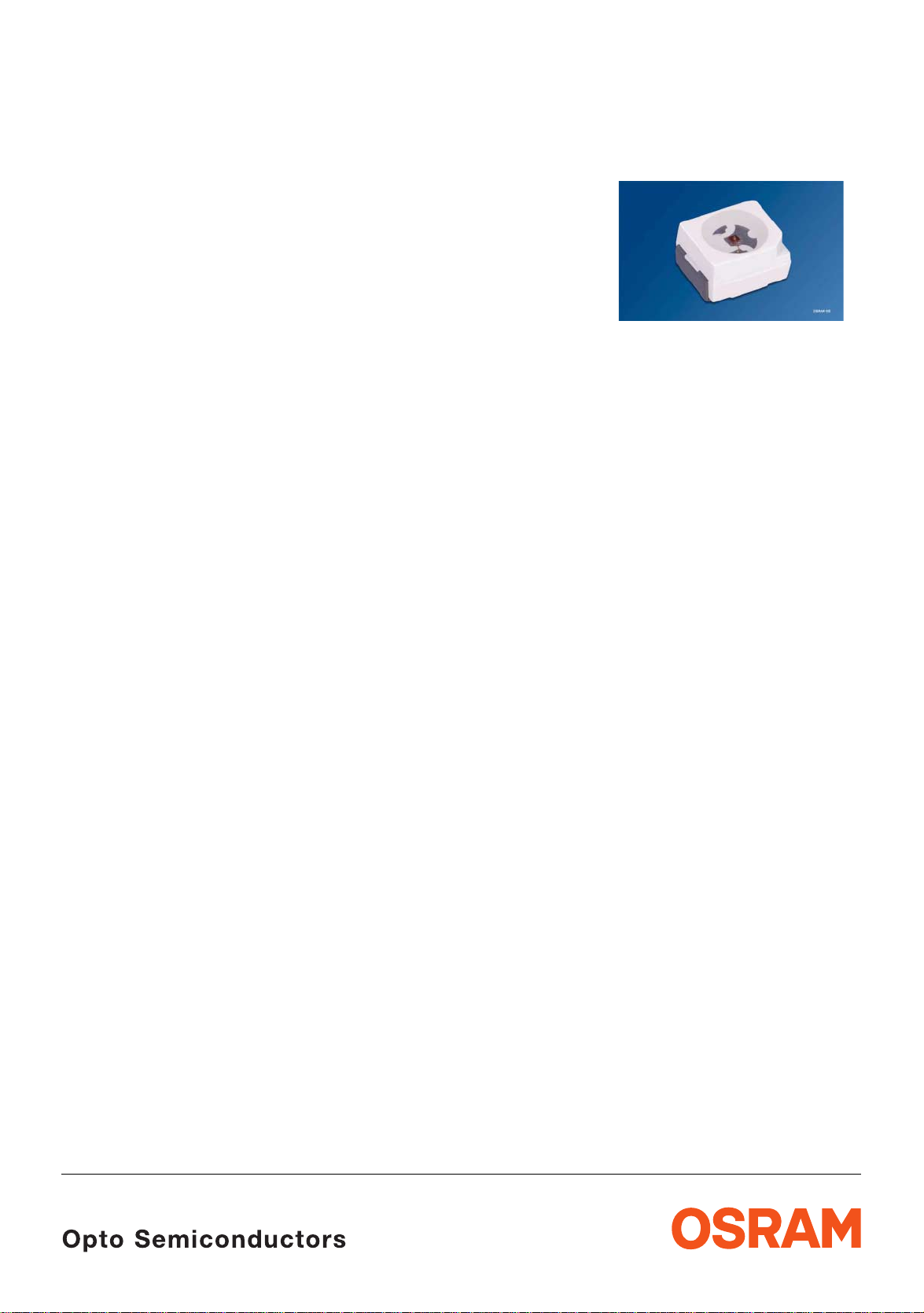
Hyper TOPLED
®
Hyper-Bright Low Current LED
Lead (Pb) Free Product - RoHS Compliant
LG T67K, LP T67K
Vorläufige Daten / Preliminary Data
Besondere Merkmale
• Gehäusetyp: weißes P-LCC-2- Ge häuse,
farbloser klarer Verguss
• Besonderheit des Bauteils: extrem breite
Abstrahlcharakteristik; ideal für Hinterleuchtungen
und Einkopplungen in Lichtleiter
• Wellenlänge: 570 nm (grün), 560 nm (pure green)
• Abstrahlwinkel: Lambertscher Strahler (120°)
• Technologie: InGaAlP
• optischer Wirkungsgrad: 4 lm/W (grün),
1,2
lm/W (pure green)
• Gruppierungsparameter: Lichtstärke,
Wellenlänge
• Verarbeitungsmethode: für alle
SMT-Bestücktech nik en geeigne t
• Lötmethode: IR Reflow Löten und
Wellenlöten
• Vorbehandlung: nach JEDEC Level 2
• Gurtung: 8-mm Gurt mit 2000/Rolle, ø180 mm
oder 8000/Rolle, ø330
• ESD-Festigkeit: ESD-sicher bis 2 kV nach
JESD22-A114-B
Anwendungen
• Informationsanzeigen im Innen- und Außenbereich
• optischer Indikator
• Hinterleuchtung (LC D, Handy, Schalter, Tasten,
Displays, Werbebeleuchtung,
Allgemeinbeleuchtung)
• Innenbeleuchtung im Automobilbereich
(z. B. Instrumentenbeleuchtung)
• Markierungsbeleuchtung (z.B. Stufen, Fluchtwege,
u.ä.)
• Einkopplung in Li chtleiter
• Laufschriftanzeigen
• Signal- und Symbolleuchten
(TTW)
mm
Features
• package: white P-LCC-2 package, colorless clear
resin
• feature of the device: extremely wide viewing
angle; ideal for backlighting and coupl ing in light
guides
• wavelength: 570 nm (green),
560
nm (pure green)
• viewing angle: Lambertian Emitter (120°)
• technology: InGaAlP
• optical efficiency: 4 lm/W (green),
lm/W (pure green)
1.2
• grouping parameter: luminous intensity,
wavelength
• assembly methods: suitable for all
assembly methods
SMT
• soldering methods: IR reflow soldering and
TTW
soldering
• preconditioning: acc. to JEDEC Level 2
• taping: 8 mm tape with 2000/reel, ø180 mm
8000/reel, ø330 mm
or
• ESD-withstand voltage: up to 2 kV acc. to
JESD22-A114-B
Applications
• indoor and outdoor displays
• optical indicators
• backlighting (LCD, cellular phones, switches, keys,
displays, illuminated advertising, general lighting)
• interior automotive lightin g
(e.g. dashboard backlighting)
• marker lights (e.g. steps, exit ways, etc.)
• coupling into light guides
• light writing displays
• signal and symbol lumi naire
2004-12-02 1
Page 2
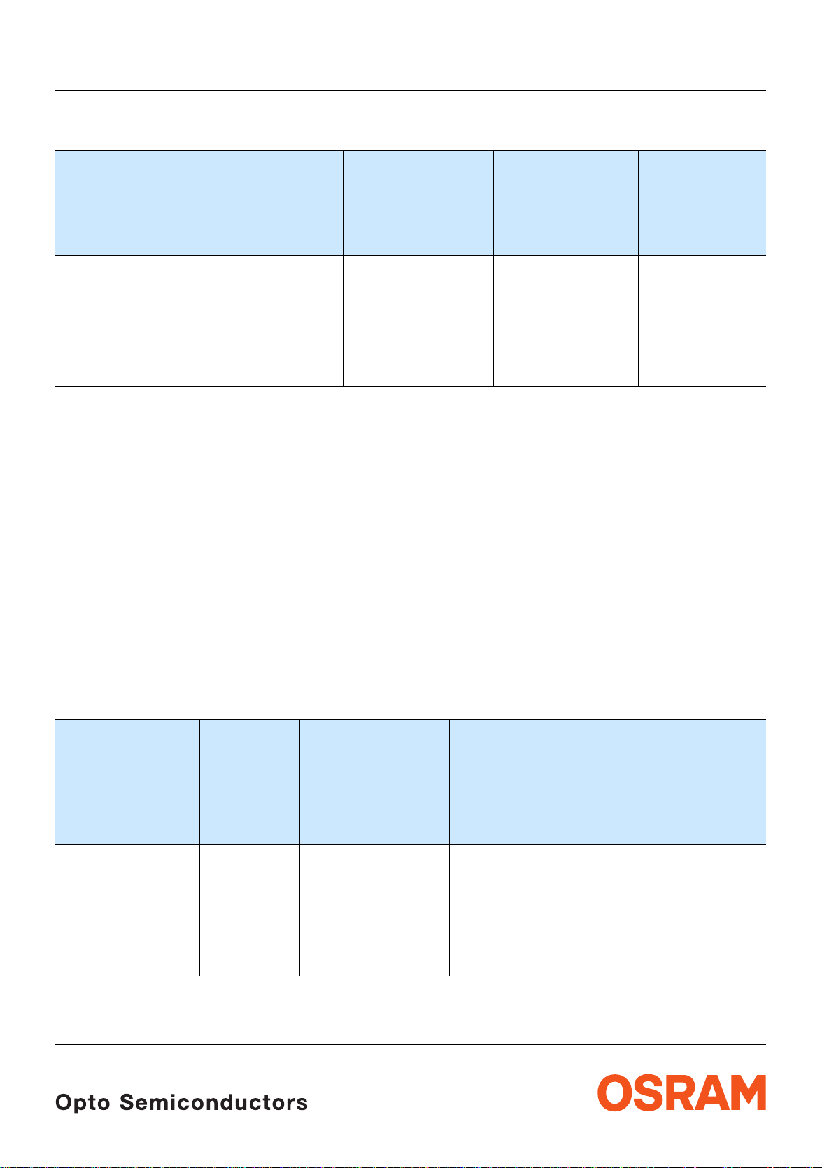
Bestellinformation Ordering Information
Typ
Type
LG T67K-G2J1-24
LG T67K-H2K1-24
LG T67K-G2K1-24
1)
Emissionsfarbe
Color of
Emission
Lichtstärke
Luminous
Intensity
Seite 15
1) page 15
IF = 2 mA
IV (mcd)
green 2.24 ... 5.60
3.55 ... 9.00
2.24 ... 9.00
Lichtstrom
Luminous
Flux
IF = 2 mA
Φ
2)
page 15
(mlm)
V
12 (typ.)
19 (typ.)
16 (typ.)
LG T67K, LP T67K
2)
Seite 15
Bestellnummer
Ordering Code
Q65110A2182
Q65110A2183
Q65110A2184
LP T67K-E1F2-25
LP T67K-F1G2-25
LP T67K-E1G2-25
Anm.: Die oben genannten Typbezeichnungen umfassen die bestellbaren Selektionen. Diese bestehen aus wenigen Helli gkeitsgruppen
Note: The above Type Numbers represent the order groups which include only a few brightness groups (see page 5 for explanation).
(siehe
Seite 5 für nähere Informationen). Es wird nur eine einzige Helligkeitsgruppe pro Gurt geliefert. Z.B.: LG T67K-G2J1-24
bedeutet, dass auf dem Gurt nur eine der Helligkeitsgruppen G2, H1, H2 oder J1 enthalten ist.
Um die Liefersicherheit zu gewährleisten, können einzelne Helligkeitsgruppen nicht bestellt werden.
Gleiches gilt für die Farben, bei denen Wellenlängengruppen gemessen und gruppiert werden. Pro Gurt wird nur eine
Wellenlängengruppe geliefert. Z.B.: LG
oder -4 enthalten ist (siehe
Um die Liefersicherheit zu gewährleisten, können einzelne Wellenlängengruppen nicht bestellt werden.
Only one group will be shipped on each reel (there will be no mixing of two groups on each reel). E.g. LG T67K-G2J1-24 means
that only one group G2, H1, H2 or J1 will be shippable for any one reel.
In order to ensure availability, single brightness groups will not be orderable.
In a similar manner for colors where wavelength groups are measured and binned, single wavelength groups will be shipped on
any one reel. E.g. LG
explanation).
In order to ensure availability, single wavelength groups will not be orderable.
pure green 0.71 ... 1.80
1.12 ... 2.80
0.71 ... 2.80
Seite 5 für nähere Information).
T67K-G2J1-24 means that only 1 wavelength group -2, -3, or -4 will be shippable (see page 5 for
T67K-G2J1-24 bedeutet, dass auf dem Gurt nur eine der Wellenlängengruppen -2, -3,
4 (typ.)
6 (typ.)
5 (typ.)
Q65110A2185
Q65110A2186
Q65110A2187
Vergleichstabelle für 10 mA Correllation Table for 10 mA
Typ
Type
LG T67K-G2J1-24
LG T67K-H2K1-24
LG T67K-G2K1-24
Emissionsfarbe
Color of
Emission
Lichtstärke
Luminous
Intensity
1) Seite 15
1) page 15
IF = 2 mA
IV (mcd)
green 2.24 ... 5.60
3.55 ... 9.00
2.24 ... 9.00
Lichtstärke
Seite 15
Luminous
Intensity
IF = 10 mA
IV (mcd)
20 (typ.)
⇒
31 (typ.)
28 (typ.)
2)
2) page 15
Lichtstrom
Seite 15
Luminous
Flux
2) page 15
IF = 10 mA
Φ
(mlm)
V
60 (typ.)
93 (typ.)
84 (typ.)
2)
LP T67K-E1F2-25
LP T67K-F1G2-25
LP T67K-E1G2-25
pure green 0.71 ... 1.80
1.12 ... 2.80
0.71 ... 2.80
Siehe auch Grafik Seite 7 / see also graph on page 7
2004-12-02 2
⇒
6 (typ.)
10 (typ.)
9 (typ.)
18 (typ.)
30 (typ.)
27 (typ.)
Page 3
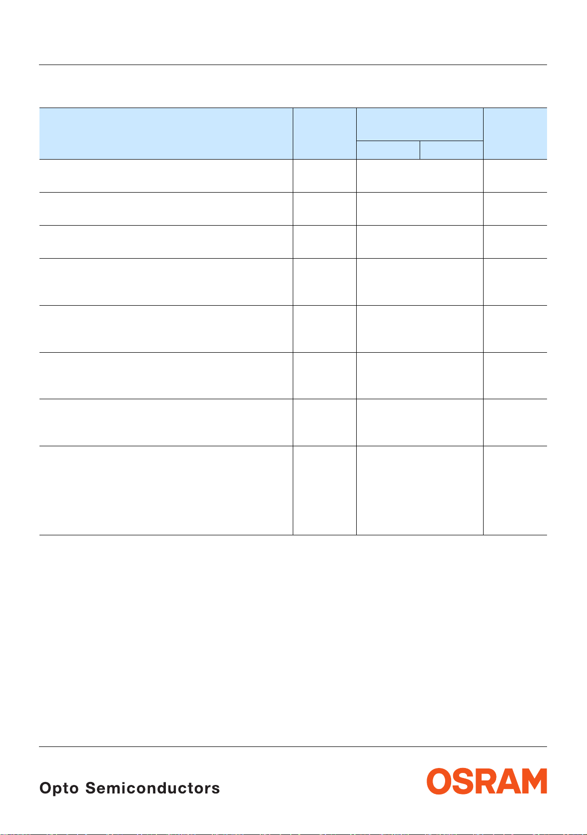
Grenzwerte Maximum Ratings
LG T67K, LP T67K
Bezeichnung
Parameter
Betriebstemperatur
Operating temperature range
Lagertemperatur
Storage temperature range
Sperrschichttemperatur
Junction temperature
Durchlassstrom
Forward current
(TA=25°C)
Stoßstrom
Surge current
t ≤ 10 µs, D = 0.005, T
3)
Sperrspannung
Reverse voltage3)
Seite 15
page 15
=25°C
A
(TA=25°C)
Symbol
Symbol
T
op
T
stg
T
j
I
F
I
FM
V
R
Wert
Value
LG LP
– 40 … + 100 °C
– 40 … + 100 °C
+ 125 °C
20 mA
100 mA
12 V
Einheit
Unit
Leistungsaufnahme
Power consumption
(TA=25°C)
Wärmewiderstand
Thermal resistance
Sperrschicht/Umgebung4)
Junction/ambient4)
page 15
Sperrschicht/Lötpad
Junction/soldering point
Seite 15
P
tot
R
th JA
R
th JS
50 mW
420
K/W
260
K/W
2004-12-02 3
Page 4
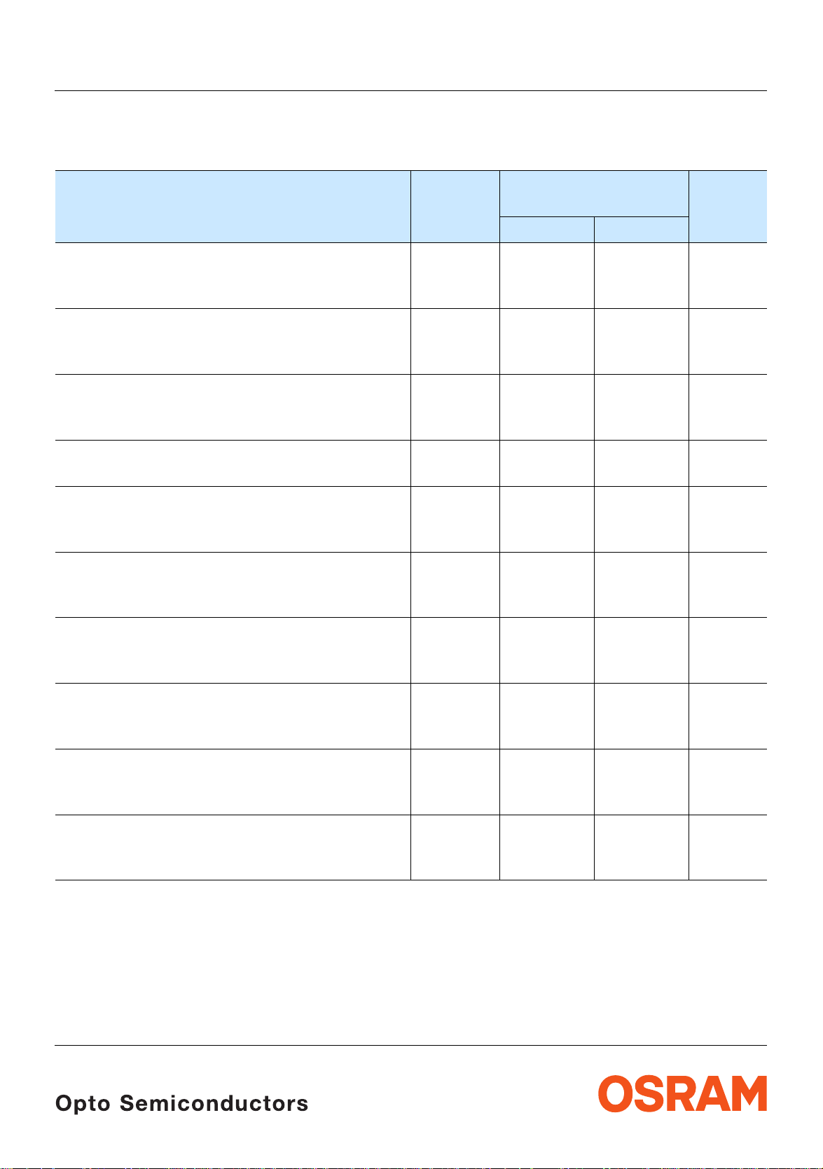
Kennwerte
Characteristics
(TA = 25 °C)
LG T67K, LP T67K
Bezeichnung
Parameter
Wellenlänge des emittierten Lichtes (typ.)
Wavelength at peak emission
I
= 2 mA
F
5)
Dominantwellenlänge
Dominant wavelength
I
= 2 mA
F
Spektrale Bandbreite bei 50 % I
Spectral bandwidth at 50 % I
I
= 2 mA
F
Seite 15
5) page 15
rel max
rel max
(typ.)
Abstrahlwinkel bei 50 % IV (Vollwinkel) (typ.)
Viewing angle at 50 % I
Durchlassspannung6)
Forward voltage
I
= 2 mA (max.)
F
6) page 15
V
Seite 15
(min.)
(typ.)
Sperrstrom (typ.)
Reverse current (max.)
V
= 12 V
R
Temperaturkoeffizient von λ
Temperature coefficient of λ
I
= 2 mA; –10°C ≤ T ≤ 100°C
F
Temperaturkoeffizient von λ
Temperature coefficient of λ
I
= 2 mA; –10°C ≤ T ≤ 100°C
F
Temperaturkoeffizient vonV
Temperature coefficient of V
I
= 2 mA; –10°C ≤ T ≤ 100°C
F
peak
peak
dom
dom
F
F
(typ.)
(typ.)
(typ.)
Optischer Wirkungsgrad (typ.)
Optical efficiency
I
= 2 mA
F
* Einzelgruppen siehe Seit e 5
Individual groups on page 5
Symbol
Symbol
Werte
Value
LG LP
λ
peak
λ
dom
∆λ
572 562 nm
570*
–4/+5
560*
± 6
22 22 nm
2ϕ 120 120 Grad
V
V
V
I
R
I
R
TC
TC
TC
η
opt
F
F
F
λpeak
λdom
V
1.7
1.8
2.2
0.01
10
1.7
1.8
2.2
0.01
10
0.11 0.10 nm/K
0.10 0.10 nm/K
– 2.3 – 2.5 mV/K
4 1.2 lm/W
Einheit
Unit
nm
deg.
V
V
V
µA
µA
2004-12-02 4
Page 5
Wellenlängengruppen (Dominantwellenlänge)
Wavelength Groups (Dominant Wavelength)
5) page 15
5)
Seite 15
LG T67K, LP T67K
Gruppe
Group
min. max. min. max.
pure green green Einheit
2 554 557 566 569 nm
3 557 560 569 572 nm
4 560 563 572 575 nm
5 563 566 nm
Helligkeits-Gruppierungsschema Brightness Groups
Helligkeitsgruppe
Brightness Group
E1
E2
F1
F2
G1
G2
H1
H2
J1
J2
K1
1)
Lichtstärke
Seite 15
Luminous Intensity
I
(mcd)
V
0.71 ... 0.90
0.90 ... 1.12
1.12 ... 1.40
1.40 ... 1.80
1.80 ... 2.24
2.24 ... 2.80
2.80 ... 3.55
3.55 ... 4.50
4.50 ... 5.60
5.60 ... 7.10
7.10 ... 9.00
1) page 15
Lichtstrom
Luminous Flux
Φ
(mlm)
V
2.5 (typ.)
3.0 (typ.)
3.8 (typ.)
4.8 (typ.)
6.0 (typ.)
7.6 (typ.)
9.5 (typ.)
12.0 (typ.)
15.0 (typ.)
19.0 (typ.)
24.0 (typ.)
2)
Seite 15
2) page 15
Unit
Anm.: Die Standardlieferform von Serientypen beinhaltet eine untere bzw. obere Familiengruppe. Diese besteht aus
Note: The standard shipping format for serial types includes a lower or upper family group of 3 or 4 individual
3 bzw. 4 Helligkeitsgruppen.
Einzelne Helligkeitsgr uppen sind nicht bestellbar.
brightness groups.
Individual brightness groups cannot be ordered.
Gruppenbezeichnung auf Etikett
Group Name on Label
Beispiel: G2-3
Example: G2-3
Helligkeitsgruppe
Brightness Group
Wellenlänge
Wavelength
G2 3
Anm.: In einer Verpackungseinheit / Gurt ist immer nur eine Gruppe für jede Selekti on enthalten.
Note: No packing unit / tape ever c ont ains more than one group for each s elec t ion.
2004-12-02 5
Page 6

Seite 15
Relative spektrale Emission2)
Relative Spectral Emission
2) page 15
V(λ) = spektrale Augenempfindlichkeit / Standard eye response curve
I
= f (λ); TA = 25 °C; IF = 2 mA
rel
100
%
I
rel
80
V
λ
60
40
greenpure-green
20
LG T67K, LP T67K
OHL00570
0
400
Abstrahlcharakteristik2)
Radiation Characteristic
I
= f (ϕ); TA = 25 °C
rel
50˚
60˚
70˚
80˚
90˚
450 500 550 600 650 700
nm
λ
Seite 15
2 page 15)
0˚10˚20˚40˚ 30˚
ϕ
1.0
0.8
0.6
0.4
0.2
0
OHL01660
100˚
1.0 0.8 0.6 0.4
2004-12-02 6
0˚ 20˚ 40˚ 60˚ 80˚ 100˚ 120˚
Page 7

LG T67K, LP T67K
F
2
OHL00801
I
OHL00800
I
0
Durchlassstrom2)
Forward Current
I
= f (VF); TA = 25 °C
F
2
10
mA
I
F
1
10
0
10
-1
10
-2
10
-3
10
1.4
1.6 1.8 2.0 2.2
Seite 15
2) page 15
OHL00802
V
Relative Lichtstärke
Relative Luminous Intensity
I
V/IV(2 mA)
= f (IF); TA = 25 °C
2
10
I
V
V (2 mA)
1
10
0
10
-1
10
0
V
Relative Lichtstärke2)
Relative Luminous Intensity
I
/ IV(25 °C)= f (Tj); IF = 2 mA
V
2) 7)
Seite 15
1010
Seite 15
2) 7) page 15
2) page 15
mA110
I
3.0
I
V
V (25˚C)
2.0
1.5
1.0
0.5
0
-60
-40 -20 0 20 40 60 ˚C 10
T
j
2004-12-02 7
Page 8

LG T67K, LP T67K
OHL01429
T
0
OHL02041
I
2
OHL02041
I
2
Maximal zulässiger Durchlassstrom
Max. Permissible Forward Current
I
= f (TA)
F
25
mA
I
F
20
15
10
T
5
T
temp. ambient
A
T
temp. solder point
S
0
0
20 40 60 80 ˚C 10
T
A
S
Zulässige Impulsbelastbarkeit IF = f (tp)
Permissible Pulse Handling Capability
Duty cycle D = parameter, TA = 25 °C
0.14
A
F
D
0.10
0.08
0.06
0.04
0.02
0
-5 1
-4
-3 -2
10
10 10
10
=
t
P
T
t
P
=
D
0.005
0.01
0.02
0.05
0.1
0.2
0.5
1
-1 0
1010
T
10 10s
t
p
I
F
Zulässige Impulsbelastbarkeit IF = f (tp)
Permissible Pulse Handling Capability
Duty cycle D = parameter, TA = 85 °C
0.14
A
F
D
0.10
0.08
0.06
0.04
0.02
0
-5 1
-4
-3 -2
10
10 10
10
=
t
P
T
-1 0
t
P
T
=
D
0.005
0.01
0.02
0.05
0.1
0.2
0.5
1
1010
10 10s
t
p
I
F
2004-12-02 8
Page 9

8)
GPLY6724
2.1 (0.083)
C
1
4 (0.157)1.5 (0.059)
2 (0.079) Cathode/Collector Marking
Maßzeichnung
Seite 15
Package Outlines
8) page 15
3.0 (0.118)
2.6 (0.102)
2.3 (0.091)
2.1 (0.083)
0.1 (0.004) (typ.)
LG T67K, LP T67K
1.7 (0.067)
0.9 (0.035)
0.7 (0.028)
4˚±1
3.3 (0.130)
3.0 (0.118)
3.4 (0.134)
athode marking
(2.4) (0.095)
3.7 (0.146)
1.1 (0.043)
0.18 (0.007)
0.12 (0.005)
0.5 (0.020)
0.6 (0.024)
0.4 (0.016)
Kathodenkennung: abgeschrägte Ecke
Cathode mark: bevelled edge
Gewicht / Approx. weight: 35 mg
8)
Gurtung / Polarität und Lage
Seite 15
Verpackungseinheit 2000/Rolle, ø180 mm
oder 8000/Rolle, ø330 mm
Method of Taping / Polarity and Orientation
8) page 15
Packing unit 2000/reel, ø180 mm or 8000/reel,
ø330 mm
A
C
2.9 (0.114)
2004-12-02 9
4 (0.157)
3.5 (0.138)
3.6 (0.142)
8 (0.315)
1.75 (0.069)
OHAY227
Page 10

Empfohlenes Lötpaddesign
0
1.5 (0.059)
2
Recommended Solder Pad
8) 9)
Seite 15
8) 9) page 15
2.6 (0.102)
LG T67K, LP T67K
IR-Reflow Löten
IR Reflow Soldering
2.6 (0.102)
4.5 (0.177)
4.5 (0.177)
1.5 (0.059)
Padgeometrie für
verbesserte Wärmeableitung
Paddesign for
improved heat dissipation
Lötstopplack
Solder resist
Cu-Fläche > 16 mm
Cu-area > 16 mm
2
OHLPY97
Empfohlenes Lötpaddesign verwendbar für TOPLED® und Power TOPLED
8)
IR Reflow Löten
Recommended Solder Pad useable for TOPLED® and Power TOPLED
IR Reflow Soldering
Seite 15
8) page 15
Padgeometrie für
verbesserte Wärmeableitung
Paddesign for
improved heat dissipation
2.3 (0.091)
0.8 (0.031)
Anode
3.3 (0.130)
®
Fläche darf elektrisch nicht beschaltet werden.
Do not use this area for electrical contact.
3.3 (0.130)
®
1.1 (0.043)
3.7 (0.146)
0.7 (0.028)
Fläche darf elektrisch nicht beschaltet werden.
Do not use this area for electrical contact.
1.5 (0.059)
Lötstoplack
Solder resist
2004-12-02 10
11.1 (0.437)
Kathode/
Cathode
2
_
Cu Fläche / 16 mm per pad
Cu-area
<
OHLPY440
Page 11

LG T67K, LP T67K
T
t
0
Lötbedingungen Vorbehandlung nach JEDEC Level 2
Soldering Conditions Preconditioning acc. to JEDEC Level 2
IR-Reflow Lötprofil für bleifreies Löten (nach J-STD-020B)
IR Reflow Soldering Profile for lead free soldering (acc. to J-STD-020B)
300
˚C
250
255 ˚C
240 ˚C
Maximum Solder Profile
Recommended Solder Profile
Minimum Solder Profile
217 ˚C
200
10 s min
30 s max
150
120 s max
100 s max
Ramp Down
6 K/s (max)
100
Ramp Up
50
3 K/s (max)
25 ˚C
0
0
50 100 150 200 250 30
Wellenlöten (TTW) (nach CECC 00802) TTW Soldering (acc. to CECC 00802)
OHLA0687
260 ˚C
245 ˚C
235 ˚C
s
+0 ˚C
-5 ˚C
±5 ˚C
+5 ˚C
-0 ˚C
300
C
250
T
235 C
200
150
CC... 130100
100
C... 260
1. Welle
1. wave
ca 200 K/s
50
0
0
50 100 150 200 250
10 s
Zwangskühlung
2 K/s
forced cooling
5 K/s
2. Welle
2. wave
Normalkurve
standard curve
Grenzkurven
limit curves
2 K/s
t
OHLY0598
s
2004-12-02 11
Page 12

Barcode-Produkt-Etikett (BPL)
S
ple
3
+ 0.3
– 0.1
Barcode-Product-Label (BPL)
LG T67K, LP T67K
Gurtverpackung Tape and Reel
OSRAM Opto
Semiconductors
(6P) BATCH NO: Batch Number
Bar Code
Lot Number(1T) LOT NO: (9D) D/C: Date Code
Bar Code
(X) PROD NO: Product Code
D
0
P
0
P
2
Product Quantity per Reel(Q)QTY:
Bar Code
FE
W
am
W
1
A
N
±0.25
13.0
Lx xxxx
Product Name
RoHS Compliant
Bin1: Bin Information Color 1
Bin2:
Bin3:
Temp ST
ML
2
260 C RT
Additional TEXT
R077 DEMY
PACKVAR: Packing Type
X - X - X(G) GROUP:
Forward Voltage Group
Wavelength Group
Brightness Group
OHA1204
P
1
Direction of unreeling
Tape dimensions in mm (inc h)
W P
8
Reel dimensions in mm (inc h)
A W N
180 (7) 8 (0.315) 60 (2.362) 8.4 + 2 (0.331 + 0.079) 14.4 (0.567)
330 (13) 8 (0.315) 60 (2.362) 8.4 + 2 (0.331 + 0.079) 14.4 (0.567)
0
4 ± 0.1
(0.157 ± 0.004)
P
1
4 ± 0.1
(0.157 ± 0.004)
min
W
2
P
2
2 ± 0.05
(0.079 ± 0.002)
W
1
Label
Gurtvorlauf:
Leader:
Gurtende:
Trailer:
D
0
1.5 + 0.1
(0.059 + 0.004)
400 mm
400 mm
160 mm
160 mm
Direction of unreeling
OHAY0324
E F
1.75 ± 0.1
(0.069 ± 0.004)
W
2 max
3.5 ± 0.05
(0.138 ± 0.002)
2004-12-02 12
Page 13

LG T67K, LP T67K
OHA00539
Moisture-sensitive label or print
el
OHA02044
el
Trockenverpackung und Materialien Dry Packing Process and Materials
EVEL
el
b
L
a
.
l
see
,
)
H
de
nk
o
a
l
c
b
r
(R
f
I
y
t
ba
.
idi
RH
um
e h
60%
/
v
age
ati
k
ared
c
el
r
r
30 ˚C
pa
_
<
%
of
90
urs
s
d to inf
r
<
o
e
or
s
,
ou
H
nd
s
ode).
ng (peak
H
our
c
ur
72
si
8
o
C a
bag contains
CAUTION
This
SEMICONDUCTORS
OISTURE SENSITIVE
O
M
OPT
mon
24
devices
g:
d,
a
d b
ene
e
op
ase reflow, or eq
is
h
k, se
-p
Floo
an
in
or
bag
h
fe in seal
bl
i
% R
it
f
is
I
0
w
lf l
h
vap
1
t
_
<
r
he
emp.
e
t
S
ow,
l
uire
nd
unted
I
q
dy
1.
ef
o
. Aft
r
s not
ed at
y
i
re
r
t
2
bo
M
)
a
2b
Sto
ces
i
or
b)
g is re
e
ev
a
n
D
nc
a) Humidi
aki
3.
b) 2
b
f
I
refere
4.
ag sea
B
e
Dat
M
4
˚
e
4 H
H
conditions
± 5 ˚C
m
e subject
y
i
oces
C
b
40
r
e 2
or
˚
th date
ll
i
time
i
<
or t
ct
m
).
w
23
w
at
or
ti
me 6
˚C
fa
ent p
Flo
o
l
ti
s
at
or
e.
at
at
r
r
Fl
l
th
d
va
th
o
:
Flo
ui
f
4
i
entical
Flo
d
labe
ow
l
el
i
ocedu
e
s
5a
r
ing,
ev
p
be
el
6
evel 5
cod
unt
ee
ate i
L
r
ev
d
vel
ake
% when rea
ure L
e
L
e s
0
ba
mo
st
e
Le
m
1
e
i
stur
ur
seal
>
t
t
ore
,
Moi
r
oi
ure
s
i
.
M
st
nk
d
H
a
, bef
Mois
l
ar
ng
C
ki
(if b
ar
STD-033 for b
t.
r
or
t
e
ba
Ye
eks
m
ica
e
d,
1
>
1 Yea
e
uire
4 W
q
JEDEC J
m
68 Hours Moi
/
ti
1
ime
t
PC
or
e
I
r
time
o
m
r
Flo
ened:
o
l
ti
o
F
o
op
l
or
ate
F
e
d
l
l 1
e
a
tim
2
Lev
l 3 Flo
and
vel
e
re
e
u
e Level 2
ur
Lev
ist
o
ture L
re
oist
s
i
M
istu
Mo
o
M
OSRAM
Desiccant
Anm.: Feuchteem pf indliche Produkte sind verpa ck t in einem Trockenbeutel zusammen mit einem Trockenmit t el und
einer Feuchteindikatorkarte
Bezüglich Trockenverpackung finden Sie weitere Hinweise im Internet und in unserem Short Form Catalog im
Kapitel “Gurtung und V erpackung” unter dem Punkt “Trockenve rpackung”. Hier sind Normenbezüge, unter
anderem ein Auszug der JEDEC-Norm, enthalten.
Note: Moisture-senisitve pro duc t is packed in a dry bag containing desic c ant and a humidity card.
Regarding dry pack y ou will find further informat ion in the internet and in the Short Form Catalog i n chapter
“Tape and Reel” under the topi c “D ry Pac k ”. He re y ou w ill als o f ind t he normative references like JE DE C.
Kartonverpackung und Materialien Transportation Packing and Materials
Barcode label
Do not eat.
Avoid metal contact.
Discard if circles overrun.
bag opening.
Please check the HIC immidiately after
check dot
WET
Comparator
bake units
15%
examine units, if necessary
If wet,
bake units
10%
examine units, if necessary
If wet,
change desiccant
5%
parts still adequately dry.
If wet,
MIL-I-8835
Humidity Indicator
OSRAM
Humidity indicator
Barcode lab
LEVEL
If blank, see
CAUTION
This bag contains
˚C).
MOISTURE SENSITIVE
at factory conditions of
OPTO SEMICONDUCTORS
Floor time see below
(if blank, seal date is identical with date code).
If blank, see bar code label
10% RH.
_
<
1. Shelf life in sealed bag: 24 months at < 40 ˚C and < 90% relative humidity (RH).
reflow, vapor-phase reflow, or equivalent processing (peak package
2. After this bag is opened, devices that will be subjected to infrared
body temp.
a) Mounted within
b) Stored at
Floor time > 1 Year
Floor time 1 Year
a) Humidity Indicator Card is > 10% when read at 23 ˚C ± 5 ˚C, or
3. Devices require baking, before mounting, if:
b) 2a or 2b is not met.
Floor time 4 Weeks
reference IPC/JEDEC J-STD-033 for bake procedure.
4. If baking is required,
Bag seal date
Date and time opened:
Moisture Level 1
Moisture Level 2
Moisture Level 2a
Moisture Level 3 Floor time 168 Hours Moisture Level 6 Floor time 6 Hours
Barcode label
Packing
Sealing label
LSY T676
Multi TOPLED
(9D) D/C:
210021998
OSRAM Opto
Semiconductors
123GH1234
(6P) BATCH NO:
245
1
0
0
11
(1T) LOT NO:
(X) PROD NO:
2004-12-02 13
bar code label
30 ˚C/60% RH.
_
<
Floor time 72 Hours
Moisture Level 4
Moisture Level 5
Moisture Level 5a
210021998
OSRAM Opto
Semiconductors
123GH1234
(6P) BATCH NO:
(1T) LOT NO:
(X) PROD NO:
Bin1: P-1-20
Bin2: Q-1-20
Bin3:
Temp ST
220 C R
ML
240 C R
2
260 C RT
2a
3
Additional TEXT
R077
PACKVAR:
0144
2000
(Q)QTY:
Muster
Floor time 48 Hours
Floor time 24 Hours
Multi TOPLED
(9D) D/C:
1
0
0
11
DEMY
R18
P-1+Q-1
(G) GROUP:
Bin1: P-1-20
Bin2: Q-1-20
Bin3:
Temp ST
220 C R
ML
240 C R
2
260 C RT
2a
LSY T676
3
Additional TEXT
0144
2000
(Q)QTY:
245
Muster
Barcode lab
DEMY
R18
R077
P-1+Q-1
PACKVAR:
(G) GROUP:
OSRAM
Page 14

LG T67K, LP T67K
Revision History: 2004-12-02
Previous Version: 2004-06-21
Page Subjects (major changes since last revision) Date of change
5 value: min. forward voltage 2004-12-02
Attention please!
The information describes the type of component and sha ll not be c ons idered as assured characte ris tics .
Terms of delivery and rights to change design reserved. Due to technical requirements components may contain
dangerous substances . For in fo rmation on the types in question ple as e c ont ac t our Sales Organization.
If printed or downloaded, please find the latest version in the Inte rnet .
Packing
Please use the recycling operators k nown to you . We can als o help you – get in touch wit h your near est sales offic e.
By agreement we will take p acking material back, if it is sorted. You m ust bear the costs of transport. For packing
material that is returned to us unsorted or which we are not obliged to accept, we shall have to invoice you for any costs
incurred.
Components used in life-su pport devices or systems must be expressly authorized fo r such purpose! Critical
components
OSRAM OS.
2004-12-02 14
10) page 15
may only be used in lif e-s upport devices or syst em s
11) page 15
with the express wr itten approval of
Page 15

LG T67K, LP T67K
Fußnoten:
1)
Helligkeitswerte werden mit einer
Stromeinprägedauer von 25
Genauigkeit von ±
2)
Wegen der besonderen Prozessbedingun gen bei der
11% ermitt elt.
ms und einer
Herstellung von LED können typische oder abgeleitete
technische Parameter nur aufgrund statistischer
Werte wiedergegeben werden. Diese stimmen nicht
notwendigerweise mit den Werten jedes einzelnen
Produktes überein, dessen Werte sich von typischen
und abgeleiteten Werten oder typischen Kennlinien
unterscheiden können. Falls erforderlich, z.B.
aufgrund technischer Ve rbesserungen, werde n diese
typischen Werte ohne weitere Ankündigung geändert.
3)
Die LED kann kurzzeitig in Sperrichtung betrieben
werden.
4)
R
ergibt sich bei Montage auf PC-Board FR 4
thJA
(Padgröße ≥ 16
5)
Wellenlängen werden mit einer Stromeinprägedauer
ms und einer Genauigkeit von ±1 nm ermittelt.
von 25
6)
Spannungswerte werden mit einer
Stromeinprägedauer vo n 1
von ±0,1
7)
Im gestrichelten Bereich der Kennlinien muss mit
V ermittelt.
mm 2 je Pad)
ms und einer Genauigk eit
erhöhten Helligkeitsunterschieden zwischen
Leuchtdioden innerhalb einer Verpackungseinheit
gerechnet werden.
8)
Maße werden wie folgt angegeben: mm (inch)
9)
Gehäuse hält TTW-Löthit z e aus nach CECC 00802
10)
Ein kritisches Bauteil ist ein Bauteil, das in
lebenserhaltenden Apparaten oder Systemen
eingesetzt wird und de ssen Defek t voraussich tlich zu
einer Fehlfunktion dieses lebenserhaltenden
Apparates oder Systems führen wird oder die
Sicherheit oder Effektivität dieses Apparates oder
Systems beeinträchtigt.
11)
Lebenserhaltende App arate oder Systeme sind für
(a) die Implantierung in den menschlichen Körper
oder
(b) für die Lebenserhaltung bestimmt.
Falls sie versagen, kann davon ausgegangen werden,
dass die Gesundheit und das Leben des Patie nten in
Gefahr ist.
Remarks:
1)
Brightness groups are tested at a current pulse
duration of 25
2)
Due to the special conditions of the manufacturing
ms and a tolera nce of ± 11%.
processes of LED, the typical data or calculated
correlations of technical parameters can only reflect
statistical figures. These do not necessarily
correspond to the actual parameters of each single
product, which could differ from t he typical data and
calculated correlations or the typical characteristic
line. If requested, e.g. because of technical
improvements, these typ. data will be changed without
any further notice.
3)
Driving the LED in reverse direction is suitable for
short term application.
4)
R
results from mounting on PC board FR 4
thJA
(pad size ≥ 16 mm 2 per pad)
5)
Wavelengths are tested at a current pu lse duration of
ms and a tolera nce of ±1 nm.
25
6)
Forward voltages are tested at a current pulse
duration of 1
7)
In the range where the line of the graph is broken, you
ms and a tolerance of ±0.1 V.
must expect higher brightness differences between
single LEDs within one pack ing unit.
8)
Dimensions are specified as follows: mm (inch).
9)
Package able to withstand TTW-soldering heat acc. to
CECC
10)
00802
A critical component is a component used in a
life-support device or system whose failure can
reasonably be expected to cause the failure of that
life-support device or system , or to affect its safety or
the effectiveness of that device or system.
11)
Life support devices or system s are intended
(a) to be implanted in the human body,
or
(b) to support and/or maintain and s us ta in human life.
If they fail, it is reasonable to assume that the health
and the life of the user may be endangered.
Published by
OSRAM Opto Semiconductors GmbH
Wernerwerkstrasse 2, D-93049 Regensburg
www.osram-os.com
© All Rights Reserved.
2004-12-02 15
 Loading...