

Page 1
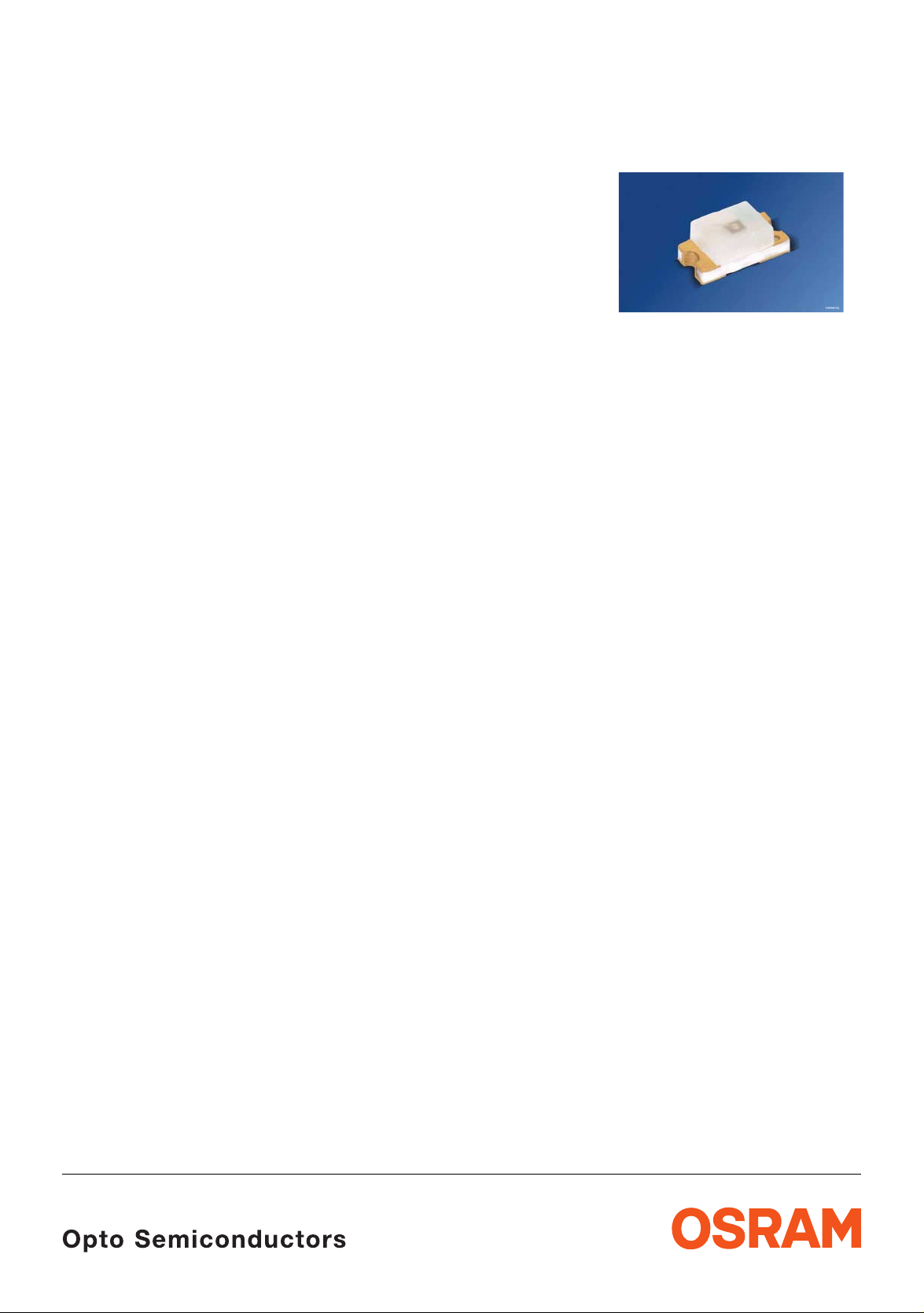
CHIPLED
Lead (Pb) Free Product - RoHS Compliant
LS Q971, LO Q971, LY Q971, LG Q971
Released
Besondere Merkmale
• Gehäusetyp: 0603, farbloser diffuser Verguss
• Besonderheit des Bauteils: kleinste Bauform
mm x 0,8 mm x 0,8 mm
1,6
• Wellenlänge: 628 nm (super-red),
nm (orange), 587 nm (gelb),
606
nm (grün)
570
• Abstrahlwinkel: extrem breite
Abstrahlcharakteristik (160°)
• Technologie: GaP (grün), GaAlP (super-red,
orange, gelb)
• optischer Wirkungsgrad: 2,5 lm/W (grün),
lm/W (super-red, orange, gelb)
1,5
• Verarbeitungsmethode: für alle
SMT-Bestücktechniken geeignet
• Lötmethode: IR Reflow Löten
• Vorbehandlung: nach JEDEC Level 2
• Gurtung: 8-mm Gurt mit 4000/Rolle, ø180 mm
• ESD-Festigkeit: ESD-sicher bis 2 kV nach
JESD22-A114-D
Features
• package: 0603, colorless diffused resin
• feature of the device: smallest package
1.6 mm x 0.8 mm x 0.8 mm
• wavelength: 628 nm (super-red),
nm (orange), 587 nm (yellow),
606
nm (green)
570
• viewing angle: extremely wide (160°)
• technology: GaP (green), GaAlP (super-red,
orange, yellow)
• optical efficiency: 2.5 lm/W (green),
lm/W (super-red, orange, yellow)
1.5
• assembly methods: suitable for all
assembly methods
SMT
• soldering methods: IR reflow soldering
• preconditioning: acc. to JEDEC Level 2
• taping: 8 mm tape with 4000/reel, ø180 mm
• ESD-withstand voltage: up to 2 kV acc. to
JESD22-A114-D
Anwendungen
• Informationsanzeigen im Innenbereich
• optischer Indikator
• Flache Hinterleuchtung (LCD, Handy,
Schalter,
• Spielsachen
2007-10-08 1
Display)
Applications
• indoor displays
• optical indicators
• flat backlighting (LCD, cellular phones,
switches, displays)
•toys
Page 2
LS Q971, LO Q971, LY Q971, LG Q971
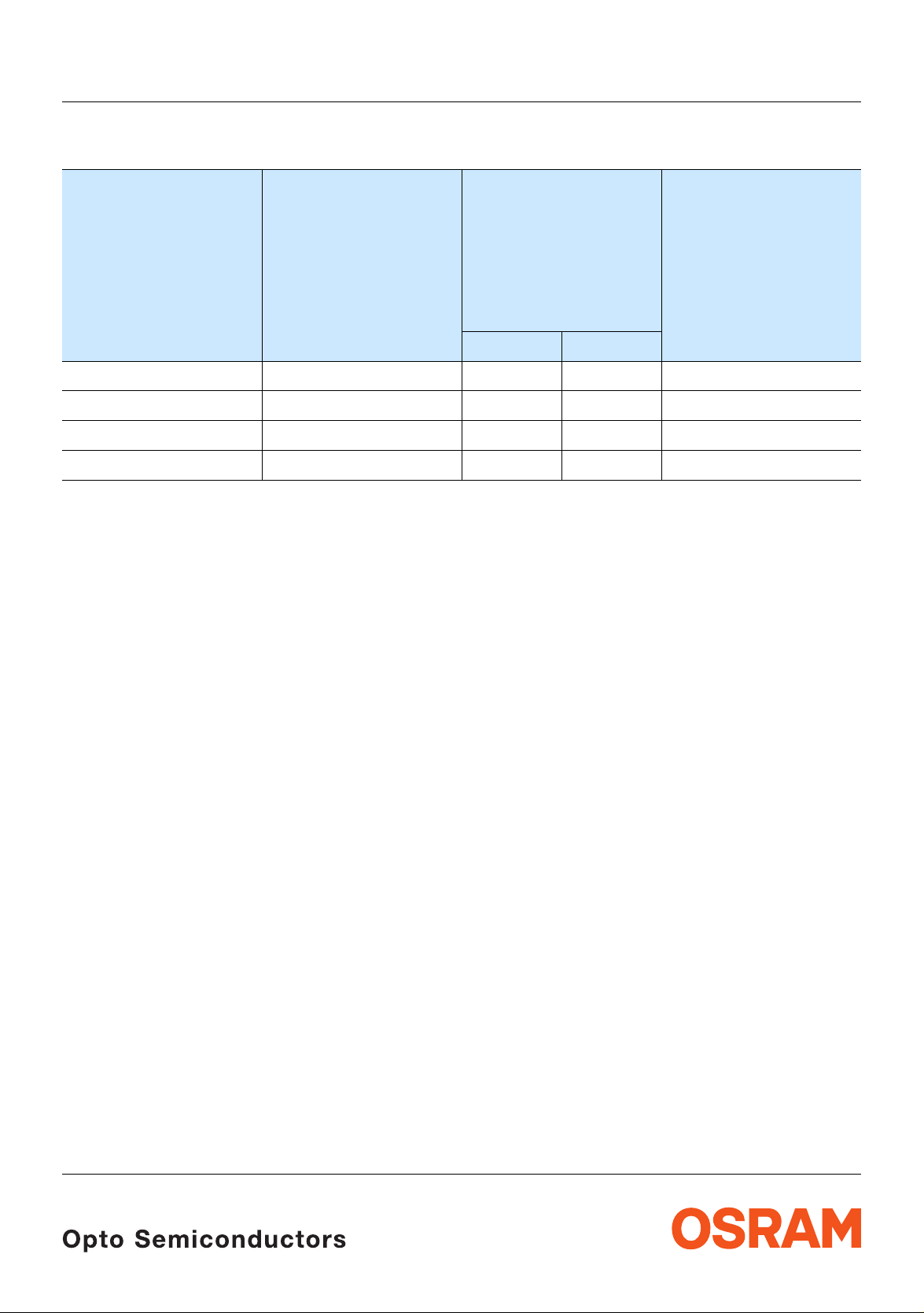
Bestellinformation Ordering Information
1) 2)
Typ
Type
Emissionsfarbe
Color of Emission
Lichtstärke
Luminous
Intensity
1) 2) page 13
I
= 20 mA
F
I
(mcd)
V
min. typ.
LS Q971 super-red 7.1 11 Q65110A4282
LO Q971 orange 4.5 9 Q65110A4285
LY Q971 yellow 2.8 6 Q62703Q4699
LG Q971 green 7.1 10 Q62702P5189
Seite 13
Bestellnummer
Ordering Code
Anm.: Die Standardlieferform von Serientypen beinhaltet alle Gruppen. Einzelne Helligkeitsgruppen
sind nicht bestellbar.
In einer Verpackungseinheit / Gurt ist immer nur eine Helligkeitsgruppe enthalten.
Note: The standard shipping format for serial types includes all groups. Individual brightness groups
cannot be ordered.
No packing unit / tape ever contains more than one brightness group.
2007-10-08 2
Page 3
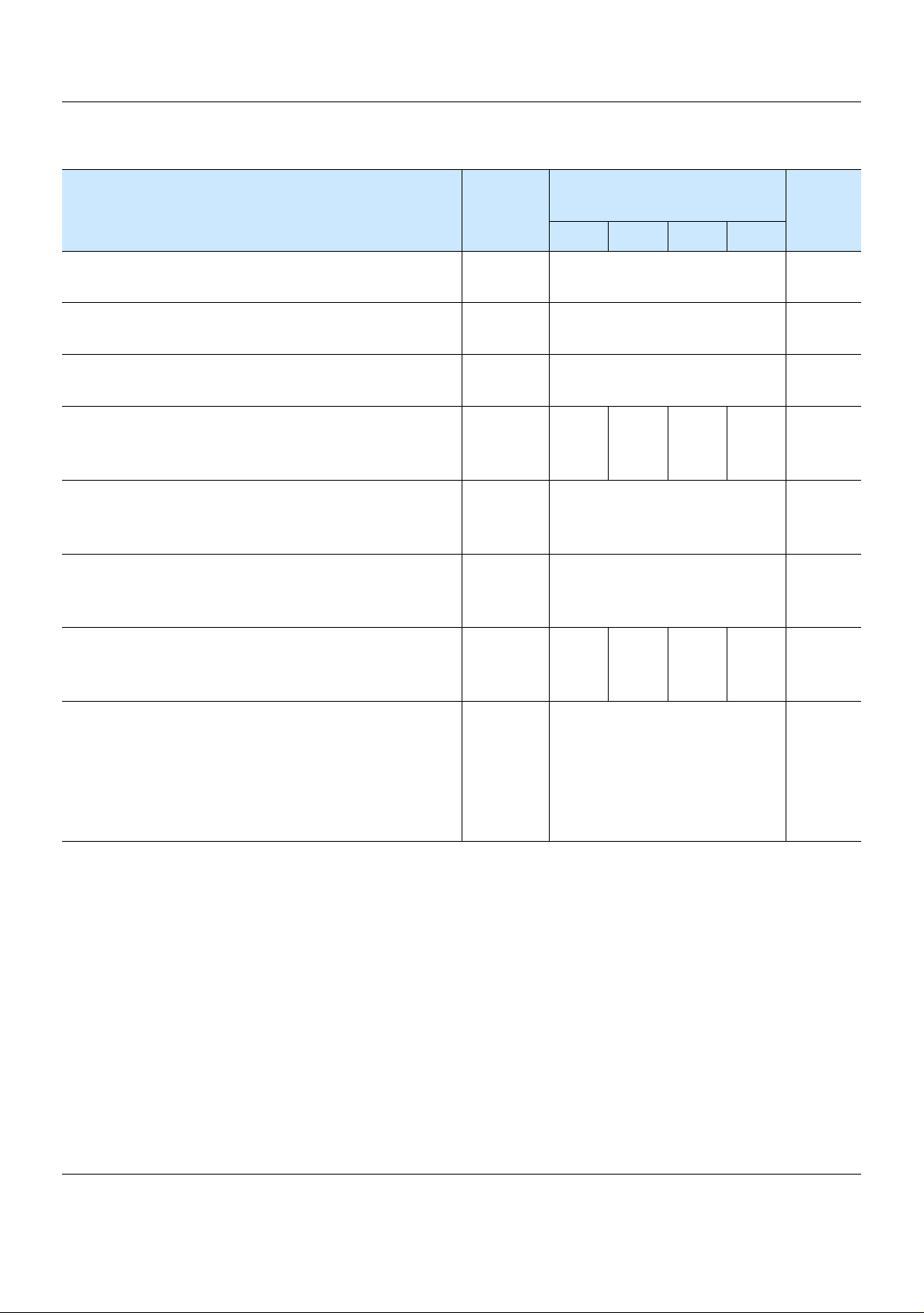
Grenzwerte Maximum Ratings
LS Q971, LO Q971, LY Q971, LG Q971
Bezeichnung
Parameter
Betriebstemperatur
Operating temperature range
Lagertemperatur
Storage temperature range
Sperrschichttemperatur
Junction temperature
Durchlassstrom
Forward current
(TA=25°C)
Stoßstrom
Surge current
t
= 10 μs, D = 0.1, TA=25°C
p
Sperrspannung
Reverse voltage
3)
3) page 13
Seite 13
(TA=25°C)
Symbol
Symbol
T
op
T
stg
T
j
I
F
I
FM
V
R
Wert
Value
Einheit
Unit
LS LO LY LG
– 30 … + 85 °C
– 40 … + 85 °C
+ 95 °C
25 25 20 25 mA
0.1 A
12 V
Leistungsaufnahme
Power consumption
(TA=25°C)
Wärmewiderstand
Thermal resistance
Sperrschicht/Umgebung
Junction/ambient
4) page 13
Sperrschicht/Lötpad
Junction/solder point
4)
Seite 13
P
tot
R
R
th JA
th JS
65 65 50 65 mW
800
K/W
450
K/W
2007-10-08 3
Page 4
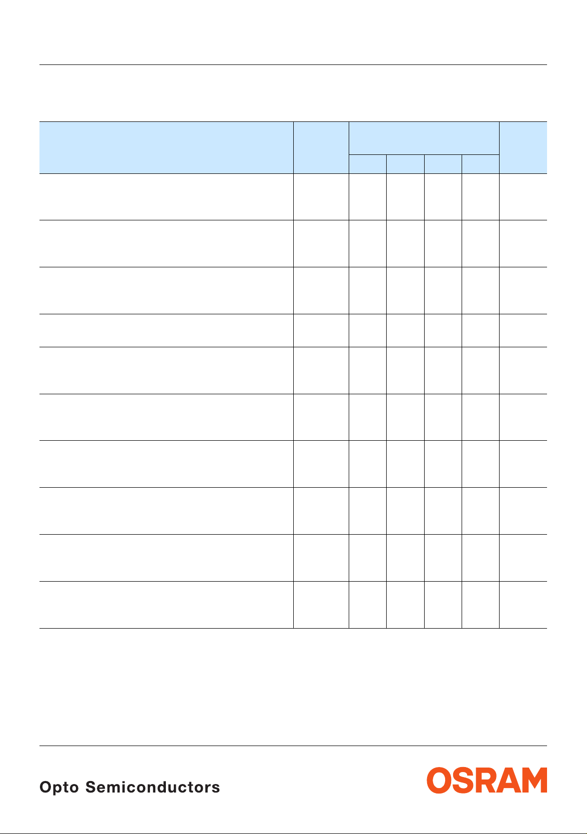
Kennwerte
Characteristics
(TA = 25 °C)
LS Q971, LO Q971, LY Q971, LG Q971
Bezeichnung
Parameter
Wellenlänge des emittierten Lichtes (typ.)
Wavelength at peak emission
I
= 20 mA
F
5)
Dominantwellenlänge
Dominant wavelength
I
= 20 mA
F
Seite 13
5) page 13
Spektrale Bandbreite (typ.)
Spectral bandwidth
I
= 20 mA
F
Abstrahlwinkel bei 50 % IV (Vollwinkel) (typ.)
Viewing angle at 50 % I
Durchlassspannung
Forward voltage
I
= 20 mA
F
6) page 13
6)
Seite 13
V
(typ.)
(max.)
Sperrstrom (typ.)
Reverse current (max.)
V
= 12 V
R
Temperaturkoeffizient von λ
Temperature coefficient of λ
I
= 20 mA; –10°C ≤ T ≤ 100°C
F
Temperaturkoeffizient von λ
Temperature coefficient of λ
I
= 20 mA; –10°C ≤ T ≤ 100°C
F
Temperaturkoeffizient von V
Temperature coefficient of V
I
= 20 mA; –10°C ≤ T ≤ 100°C
F
peak
peak
dom
dom
F
F
(typ.)
(typ.)
(typ.)
Optischer Wirkungsgrad (typ.)
Optical efficiency
I
= 20 mA
F
Symbol
Symbol
Werte
Values
LS LO LY LG
λ
peak
λ
dom
635 610 589 572 nm
628 606 587 570 nm
Δλ 35 35 40 30 nm
2ϕ 160 160 160 160 Grad
V
V
I
R
I
R
TC
TC
TC
η
F
F
λpeak
λdom
V
opt
1.9
2.6
0.02
100
2.1
2.6
0.02
100
2.1
2.6
0.02
100
2.2
2.6
0.02
100
0.11 0.11 0.11 0.10 nm/K
0.06 0.06 0.08 0.06 nm/K
– 1.6 – 1.6 – 1.7 – 1.4 mV/K
1.5 1.5 1.5 2.5 lm/W
Einheit
Unit
deg.
V
V
μA
μA
2007-10-08 4
Page 5

LS Q971, LO Q971, LY Q971, LG Q971
Relative spektrale Emission
Relative Spectral Emission
2)
2) page 13
Seite 13
V(λ) = spektrale Augenempfindlichkeit / Standard eye response curve
I
= f (λ); TA = 25 °C; IF = 20 mA
rel
100
%
I
rel
80
V
λ
60
green
40
20
yellow
orange
super red
OHL02651
0
400
Abstrahlcharakteristik
2)
Radiation Characteristic
I
= f (ϕ); TA = 25 °C
rel
50˚
60˚
70˚
80˚
90˚
450 500 550 600 650 700
nm
λ
Seite 13
2) page 13
0˚10˚20˚40˚ 30˚
ϕ
1.0
0.8
0.6
0.4
0.2
0
OHL00408
100˚
1.0 0.8 0.6 0.4
2007-10-08 5
0˚ 20˚ 40˚ 60˚ 80˚ 100˚ 120˚
Page 6

LS Q971, LO Q971, LY Q971, LG Q971
Durchlassstrom
Forward Current
I
= f (VF); TA = 25 °C
F
2
10
mA
I
F
1
10
0
10
-1
10
1.5
2.0 2.5 3.0 3.5
2)
2) page 13
Seite 13
OHL00636
V
V
F
Maximal zulässiger Durchlassstrom
Max. Permissible Forward Current
I
= f (TA)
F
40
mA
I
F
35
30
green
25
OHL02653
2) 7)
Relative Lichtstärke
Seite 13
Relative Luminous Intensity
I
V/IV(20 mA)
I
Relative Lichtstärke
= f (IF); TA = 25 °C
1
10
I
V
V
(20 mA)
0
10
5
-1
10
5
-2
10
-1 0
10
10 10
55
2)
Seite 13
Relative Luminous Intensity
I
V/IV(25 °C)
I
= f (TA); IF = 20 mA
2
I
V
V
(25 ˚C)
1.6
1.2
super red
orange
yellow
green
2) 7) page 13
OHL00426
12
mA
10
I
F
2) page 13
OHL02652
20
yellow
orange
15
10
5
0
super red
TT
temp. ambient
T
A
temp. solder point
T
S
0
20 40 60 80 100
A
S
˚C
T
2007-10-08 6
0.8
0.4
0
-20 0 20 40 60 ˚C 100
T
j
Page 7

LS Q971, LO Q971, LY Q971, LG Q971
Maßzeichnung
8)
Package Outlines
ø0.5 (ø0.020)
ø0.3 (ø0.012)
Cathode
mark
Seite 13
8) page 13
0.9 (0.035)
0.7 (0.028)
1.7 (0.067)
1.5 (0.059)
0.9 (0.035)
0.7 (0.028)
0.4 (0.016)
0.2 (0.008)
0.9 (0.035)
1.1 (0.043)
0.4 (0.016)
0.2 (0.008)
Soldering terminal
Soldering terminal
0.9 (0.035)
may flow in x, y direction
0.7 (0.028)
0.7 (0.028)
0.5 (0.020)
Cathode mark
C
A
GEOY6989
Gewicht / Approx. weight: 1.4 mg
8)
Gurtung / Polarität und Lage
Seite 13
Verpackungseinheit: 4 Rollen mit 4000/Rolle,
8 mm Gurt, ø180 mm
Method of Taping / Polarity and Orientation
8) page 13
Packing unit: 4 reels with 4000/reel,
8 mm tape, ø180 mm
±0.1 (0.004)
2 (0.079)
±0.1 (0.004)
4 (0.157)
0.2 (0.008)
0.75 (0.030)
±0.05 (0.002)
±0.1 (0.004)
1.5 (0.059)
0.95 (0.037)
4 (0.157)
+0.1 (0.004)
±0.05 (0.002)
±0.1 (0.004)
±0.1 (0.004)
±0.1 (0.004)
1.75 (0.069)
±0.05 (0.002)
1.8 (0.071)
3.5 (0.138)
C
±0.2 (0.008)
8 (0.315)
A
OHAY1539
2007-10-08 7
Page 8

Empfohlenes Lötpaddesign
Recommended Solder Pad
8)
Seite 13
8) page 13
LS Q971, LO Q971, LY Q971, LG Q971
IR Reflow Löten
IR Reflow Soldering
0.7 (0.028)
0.8 (0.031)
0.8 (0.031)
0.8 (0.031)
OHAPY606
Empfohlenes Lötpaddesign verwendbar für CHIPLED und Chipled - Bauform 0603
IR Reflow Löten
8) 9)
Seite 13
Recommended Solder Pad useable for CHIPLED and Chipled - Package 0603
IR Reflow Soldering
8) 9) page 13
2.25 (0.089)
0.225 (0.009)
0.35 (0.014)
0.8 (0.031)
0.3 (0.012)
0.5 (0.020)
2007-10-08 8
0.65 (0.026)
OHPY0203
Page 9

LS Q971, LO Q971, LY Q971, LG Q971
Lötbedingungen Vorbehandlung nach JEDEC Level 2
Soldering Conditions Preconditioning acc. to JEDEC Level 2
IR-Reflow Lötprofil (nach CECC 00802)
IR Reflow Soldering Profile (acc. to CECC 00802)
250
˚C
T
200
150
100
50
0
0:00
2-3 K/s
0:30 1:00 1:30 2:00 2:30 3:00 3:30 4:00 4:30 5:00 5:30
T
= 183 ˚C = 70 s
t
T
max
= 245 ˚C
IR-Reflow Lötprofil für bleifreies Löten (nach J-STD-020B) IR Reflow Soldering Profile for lead free soldering (acc. to J-STD-020B)
300
˚C
250
T
255 ˚C
240 ˚C
217 ˚C
200
Maximum Solder Profile
Recommended Solder Profile
Minimum Solder Profile
30 s max
2-3 K/s
t
10 s min
OHLA0685
min
260 ˚C
245 ˚C
235 ˚C
OHLA0687
+0 ˚C
-5 ˚C
±5 ˚C
+5 ˚C
-0 ˚C
150
120 s max
100
Ramp Up
50
3 K/s (max)
25 ˚C
0
0
50 100 150 200 250 300
2007-10-08 9
Ramp Down
6 K/s (max)
100 s max
s
t
Page 10

Barcode-Produkt-Etikett (BPL) Barcode-Product-Label (BPL)
LS Q971, LO Q971, LY Q971, LG Q971
Gurtverpackung Tape and Reel
OSRAM Opto
Semiconductors
(6P) BATCH NO: Batch Number
Bar Code
Lot Number(1T) LOT NO: (9D) D/C: Date Code
Bar Code
(X) PROD NO: Product Code
D
0
P
0
P
2
Bin1: Bin Information Color 1
Lx xxxx
Product Name
RoHS Compliant
Product Quantity per Reel(Q)QTY:
Bar Code
Sample
W
1
±0.25
13.0
FE
A
N
W
Bin2:
Bin3:
ML2Temp ST
260 C RT
Additional TEXT
R077 DEMY
PACKVAR: Packing Type
X - X - X(G) GROUP:
Forward Voltage Group
Wavelength Group
Brightness Group
OHA12043
P
1
Direction of unreeling
W
2
Label
Gurtvorlauf:
Leader:
Gurtende:
Trailer:
Direction of unreeling
400 mm
400 mm
160 mm
160 mm
OHAY0324
Tape dimensions in mm (inch)
W P
+ 0.3
8
– 0.1
0
4 ± 0.1
(0.157 ± 0.004)
P
1
4 ± 0.1
(0.157 ± 0.004)
P
2
2 ± 0.05
(0.079 ± 0.002)
D
0
1.5 + 0.1
(0.059 + 0.004)
E F
1.75 ± 0.1
(0.069 ± 0.004)
3.5 ± 0.05
(0.138 ± 0.002)
Reel dimensions in mm (inch)
A W N
min
W
1
W
2 max
180 (7) 8 (0.315) 60 (2.362) 8.4 + 2 (0.331 + 0.079) 14.4 (0.567)
2007-10-08 10
Page 11

LS Q971, LO Q971, LY Q971, LG Q971
Trockenverpackung und Materialien
Dry Packing Process and Materials
Moisture-sensitive label or print
L
E
V
l
E
e
e
b
e
L
a
s
l
,
).
e
k
H
d
n
o
a
l
R
c
b
(
r
If
a
y
b
.
it
d
H
i
m
R
u
%
h
0
e
6
e
/
v
i
g
d
t
C
a
˚
re
la
k
a
0
c
e
r
S
f
3
a
N
E
r
s
R
n
p
_
<
i
%
IV
in
f
O
k
0
O
T
s
o
to
T
I
a
r
ta
9
I
e
.
s
S
u
s
C
n
d
)
r
r
<
p
n
o
e
N
o
U
(
e
T
o
u
t
d
rs
H
io
d
E
,
c
o
D
c
t
g
n
s
i
u
o
e
r
2
g
N
j
U
S
a
d
o
in
c
˚C
H
u
7
a
b
s
n
O
E
8
H
o
e
5
C
b
u
s
o
t
A
U
is
T
h
C
T
IS
S
O
O
M
T
P
O
o
m
4
e
2
:
d
,
g
w
d
a
lo
e
b
f
n
d
re
e
e
e
l
p
e
e
a
s
s
o
e
a
,
s
i
h
k
s
l
n
g
n
-p
i
F
r
a
la
in
e
o
b
b
h
f
p
%
it
li
f
s
.
i
I
a
0
f
p
l
h
w
1
b
t
v
e
,
m
d
_
<
r
h
e
e
w
r
e
te
t
t
i
S
o
d
ft
a
n
l
u
y
.
f
n
u
A
I
q
d
1
d
e
o
.
r
o
s
e
y
i
re
r
t
2
b
i
M
o
s
b
t
)
id
r
e
2
a
S
s
r
m
i
ic
)
u
v
o
b
g
e
e
H
a
c
in
D
)
n
k
2
.
a
)
a
re
3
b
e
b
f
l
f
I
a
re
.
e
4
s
g
a
a
B
e
t
a
D
o
M
M
4
˚
C
R
e
s
4
H
e
I
c
a
±
c
2
0
m
e
e
y
M
E
s
h
t
n
s
e
c
e
i
r
v
o
,
c
r
a
b
ti
r
o
.
o
H
R
n
i
k
r
a
o
t
a
m
c
i
t
o
n
ir
u
q
J
/
e
C
P
I
e
t
a
d
im
t
d
n
e
r
u
t
u
is
t
s
i
o
s
i
o
M
o
M
6
i
d
o
r
t
C
b
4
r
h
˚
e
o
l
r
im
<
t
l
it
t
.
p
i
o
3
c
m
e
t
)
t
r
i
o
2
w
t
w
n
a
l
o
C
l
t
t
im
˚
fa
r
e
.
F
a
t
l
t
lo
a
o
e
a
a
a
r
ic
r
F
l
o
t
d
v
th
l
o
i
u
e
n
a
F
o
u
f:
d
l
b
4
i
e
e
w
q
e
l
r
a
F
,
d
l
i
5
c
lo
e
g
a
n
l
o
v
e
e
s
n
5
r
i
e
e
i
e
b
d
t
l
h
v
p
6
L
o
n
e
e
te
e
l
e
v
u
w
e
e
a
k
e
r
L
e
o
s
d
v
a
%
e
L
l
tu
r
m
e
b
e
0
a
s
u
i
r
1
t
e
L
re
m
e
r
o
o
s
e
u
s
f
i
>
t
r
fo
M
,
o
s
u
3
i
k
is
e
t
3
M
o
n
b
is
0
a
,
rd
M
o
l
g
a
D
M
b
r
T
if
C
(
.
a
S
t
r
s
e
e
a
k
s
J
e
Y
r
e
,
C
1
u
e
Y
d
E
o
e
>
1
W
D
H
e
4
E
8
m
e
6
ti
1
:
m
e
r
i
d
o
t
m
e
r
e
i
o
t
l
o
n
m
i
r
F
o
e
t
l
o
p
r
F
o
o
l
o
F
o
e
l
1
l
F
2
e
a
l
v
2
e
e
l
v
3
L
e
e
l
v
L
e
e
v
e
L
r
e
L
re
e
u
t
r
u
t
is
M
A
R
S
O
Desiccant
Anm.: Feuchteempfindliche Produkte sind verpackt in einem Trockenbeutel zusammen mit einem Trockenmittel und
einer Feuchteindikatorkarte
Bezüglich Trockenverpackung finden Sie weitere Hinweise im Internet und in unserem Short Form Catalog im
Kapitel “Gurtung und Verpackung” unter dem Punkt “Trockenverpackung”. Hier sind Normenbezüge, unter
anderem ein Auszug der JEDEC-Norm, enthalten.
Note: Moisture-senisitve product is packed in a dry bag containing des iccant and a humidity card.
Regarding dry pack you will find further information in the internet and in the Short Form Catalog in chapter
“Tape and Reel” under the topic “Dry Pack”. Here you will also find the normative references like JEDEC.
Kartonverpackung und Materialien Transportation Packing and Materials
Barcode label
Do not eat.
Avoid metal contact.
Discard if circles overrun.
bag opening.
Please check the HIC immidiately after
check dot
WET
Comparator
bake units
15%
examine units, if necessary
If wet,
bake units
10%
examine units, if necessary
If wet,
change desiccant
5%
parts still adequately dry.
If wet,
MIL-I-8835
Humidity Indicator
OSRAM
Humidity indicator
Barcode label
OHA00539
O
S
S
em
R
A
ico
M
(6P) BATCH
O
n
d
u
c
to
NO:
(1T) LOT NO
210021998
:
123GH1234
(X) PROD NO:
11
(9D) D/C:
0
0
1
245
(Q)QTY:
2000
Muster
2007-10-08 11
p
t
o
rs
Multi TOPLED
LSY T676
0144
Bin1: P-1-20
Bin2: Q-1-20
Bin3:
ML
2
Temp S
2a
220 C R
3
240 C R
T
260 C
Additional TE
R077
RT
PACKVAR:
XT
(G) GROUP:
R18
DEMY
P-1+Q-1
OHA02624
Page 12

LS Q971, LO Q971, LY Q971, LG Q971
Revision History: 2007-10-08
Previous Version: 2005-06-30
Page Subjects (major changes since last revision) Date of change
9 recommended solder pad
4 forward voltage
3 pad size from 16 mm2 to 5 mm
11 annotations 2002-07-23
3, 4 value (reverse voltage from 5 V to 12 V) 2002-09-18
2 ordering code 2002-09-19
3 ambient temperature 2003-09-04
all new template 2004-03-22
all RoHS compliant 2004-08-12
1 ESD-withstand voltage 2004-08-30
10 Product Label acc. to OS-IN-2005-015 2005-05-18
2
all new colors: super-red, orange 2005-06-30
2 new brightness grouping of LY Q971 - new Q-number 2007-10-08
Attention please!
The information describes the type of component and shall not be considered as assured characteristics.
Terms of delivery and rights to change design reserved. Due to technical requirements components may contain
dangerous substances. For information on the types in question please contact our Sales Organization.
If printed or downloaded, please find the latest version in the Internet.
Packing
Please use the recycling operators known to you. We can also help you – get in touch with your nearest sales office.
By agreement we will take packing material back, if it is sorted. You must bear the costs of transport. For packing
material that is returned to us unsorted or wh ich we are not obliged to accept, we shall hav e to invoice you for any costs
incurred.
Components used in life-support devices or systems must be expressly authorized for such purpose! Critical
components
OSRAM OS.
10) page 13
may only be used in life-support devices or systems
11) page 13
with the express written approval of
2007-10-08 12
Page 13

LS Q971, LO Q971, LY Q971, LG Q971
Fußnoten:
1)
Helligkeitswerte werden mit einer
Stromeinprägedauer von 25
Genauigkeit von ±
2)
Wegen der besonderen Prozessbedingungen bei der
11% ermittelt.
ms und einer
Herstellung von LED können typische oder abgeleitete
technische Parameter nur aufgrund statistischer
Werte wiedergegeben werden. Diese stimmen nicht
notwendigerweise mit den Werten jedes einzelnen
Produktes überein, dessen Werte sich von typischen
und abgeleiteten Werten oder typischen Kennlinien
unterscheiden können. Falls erforderlich, z.B.
aufgrund technischer Verbesserungen, werden diese
typischen Werte ohne weitere Ankündigung geändert.
3)
Die LED kann kurzzeitig in Sperrichtung betrieben
werden.
4)
Montage auf PC-Board FR 4 (Padgröße ≥ 5 mm2)
5)
Wellenlängen werden mit einer Stromeinprägedauer
von 25
6)
7)
ms und einer Genauigkeit von ±1 nm ermittelt.
Spannungswerte werden mit einer
Stromeinprägedauer von 1
von ±0,1
V ermittelt.
ms und einer Genauigkeit
Im gestrichelten Bereich der Kennlinien muss mit
erhöhten Helligkeitsunterschieden zwischen
Leuchtdioden innerhalb einer Verpackungseinheit
gerechnet werden.
8)
Maße werden wie folgt angegeben: mm (inch)
9)
Empfohlene Lötpastendicke: 120 µm
10)
Ein kritisches Bauteil ist ein Bauteil, das in
lebenserhaltenden Apparaten oder Systemen
eingesetzt wird und dessen Defekt voraussichtlich zu
einer Fehlfunktion dieses lebenserhaltenden
Apparates oder Systems führen wird oder die
Sicherheit oder Effektivität dieses Apparates oder
Systems beeinträchtigt.
11)
Lebenserhaltende Apparate oder Systeme sind für
(a) die Implantierung in den menschlichen Körper
oder
(b) für die Lebenserhaltung bestimmt.
Falls sie versagen, kann davon ausgega ngen werden,
dass die Gesundheit und das Leben des Patienten in
Gefahr ist.
Remarks:
1)
Brightness groups are tested at a current pulse
duration of 25
2)
Due to the special conditions of the manufacturing
ms and a tolerance of ± 11%.
processes of LED, the typical data or calculated
correlations of technical parameters can only reflect
statistical figures. These do not necessarily
correspond to the actual parameters of each single
product, which could differ from the typical data and
calculated correlations or the typical characteristic
line. If requested, e.g. because of technical
improvements, th ese typ . data w ill be changed without
any further notice.
3)
Driving the LED in reverse direction is suitable for
short term application.
4)
Mounted on PC board FR 4 (pad size ≥ 5 mm2)
5)
Wavelengths are tested at a current pulse duration of
25
ms and a tolerance of ±1 nm.
6)
Forward voltages are tested at a current pulse
duration of 1
7)
In the range where the line of the graph is broken , you
ms and a tolerance of ±0.1 V.
must expect higher brightness differences between
single LEDs within one packing unit.
8)
Dimensions are specified as follows: mm (inch).
9)
Recommended thickness of solder paste: 120 µm
10)
A critical component is a component used in a
life-support device or system whose failure can
reasonably be expected to cause the failure of that
life-support device or system, or to affect its safety or
the effectiveness of that device or system.
11)
Life support devices or systems are intended
(a) to be implanted in the human body,
or
(b) to support and/or maintain and sustain human life.
If they fail, it is reasonable to assume that the health
and the life of the user may be endangered.
Published by
OSRAM Opto Semiconductors GmbH
Wernerwerkstrasse 2, D-93049 Regensburg
www.osram-os.com
© All Rights Reserved.
2007-10-08 13
 Loading...