

Page 1
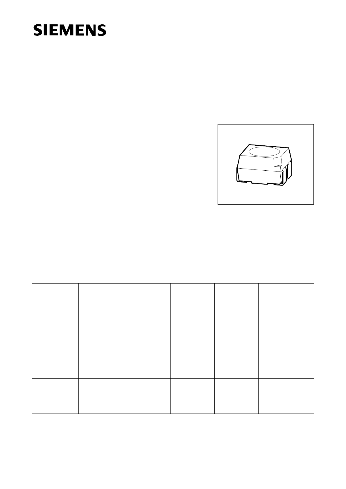
Multi TOPLED
®
Bright Green Die
Besondere Merkmale
● Gehäusebauform: P-LCC-4
● Gehäusefarbe: weiß
● als optischer Indikator einsetzbar
● zur Hinterleuchtung, Lichtleiter- und Linseneinkopplung
● für alle SMT-Bestück- und Löttechniken geeignet
● gegurtet (8-mm-Filmgurt)
● Störimpulsfest nach DIN 40839
LOG T671, LSG T671
Features
● P-LCC-4 package
● color of package: white
● for use as optical indicator
● for backlighting, optical coupling into light pipes and lenses
● suitable for all SMT assembly and soldering methods
● available taped on reel (8 mm tape)
● load dump resistant acc. to DIN 40839
Typ
Emissionsfarbe
Farbe der
Lichtaustritts-
Lichtstärke
fläche
Type
LOG T671-HO
LOG T671-LO
Color of
Emission
orange/
green
Color of the
Light Emitting
Area
Luminous
Intensity
I
= 10 mA
F
I
(mcd)
V
colorless clear ≥ 2.5
(8.0 typ.)
≥ 10.0
(15.0 typ.)
Lichtstrom
Luminous
Flux
I
= 10 mA
F
ΦV (mlm)
24 (typ.)
45 (typ.)
VPL06837
Bestellnummer
Ordering Code
Q62703-Q3632
Q62703-Q3633
LSG T671-HK
LSG T671-J
LSG T671-K
LSG T671-JL
Streuung der Lichtstärke in einer Verpackungseinheit I
Luminous intensity ratio in one packaging unit I
super-red/
green
colorless clear 2.5 ... 12.5
4.0 ... 8.0
6.3 ... 12.5
6.3 ... 20.0
/ I
V max
V max
/ I
V min
≤ 2.0.
18 (typ.)
30 (typ.)
-
V min
Q62703-Q3154
Q62703-Q3156
Q62703-Q3157
Q62703-Q3155
≤ 2.0.
Semiconductor Group 1 11.96
Page 2
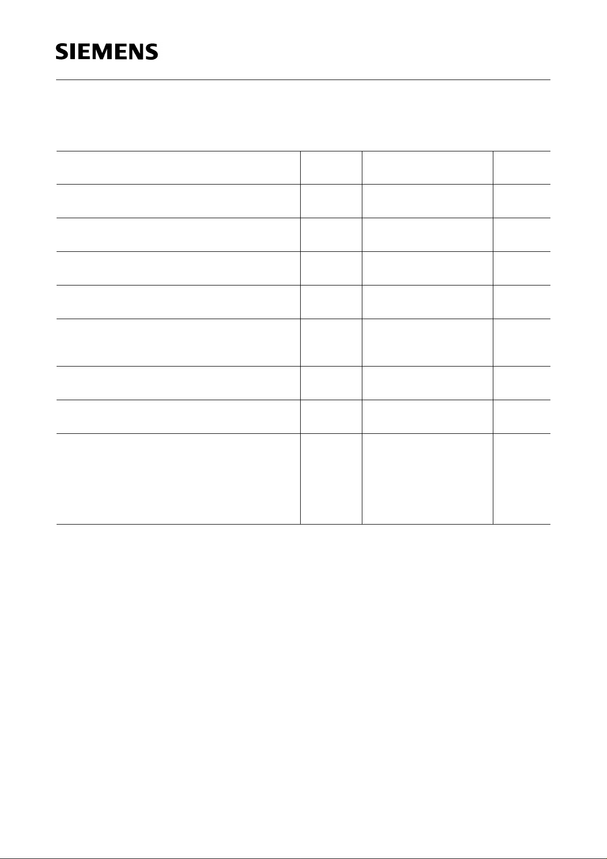
Grenzwerte
Maximum Ratings
LOG T671, LSG T671
Bezeichnung
Parameter
Betriebstemperatur
Operating temperature range
Lagertemperatur
Storage temperature range
Sperrschichttemperatur
Junction temperature
Durchlaßstrom
Forward current
Stoßstrom
Surge current
t ≤ 10 µs, D = 0.005
Sperrspanung
Reverse voltage
Verlustleistung
Power dissipation
Wärmewiderstand
Thermal resistance
Sperrschicht / Umgebung
Junction / air
)
Montage auf PC-board*
mounted on PC board*) (pad size ≥ 16 mm2)
(Padgröße ≥ 16 mm2)
Symbol
Symbol
T
op
T
stg
T
j
I
F
I
FM
V
R
P
tot
R
th JA
Werte
Values
Einheit
Unit
– 55 ... + 100 ˚C
– 55 ... + 100 ˚C
+ 100 ˚C
30 mA
0.5 A
5V
100 mW
400 K/W
)
PC-board: FR4
*
Semiconductor Group 2
Page 3
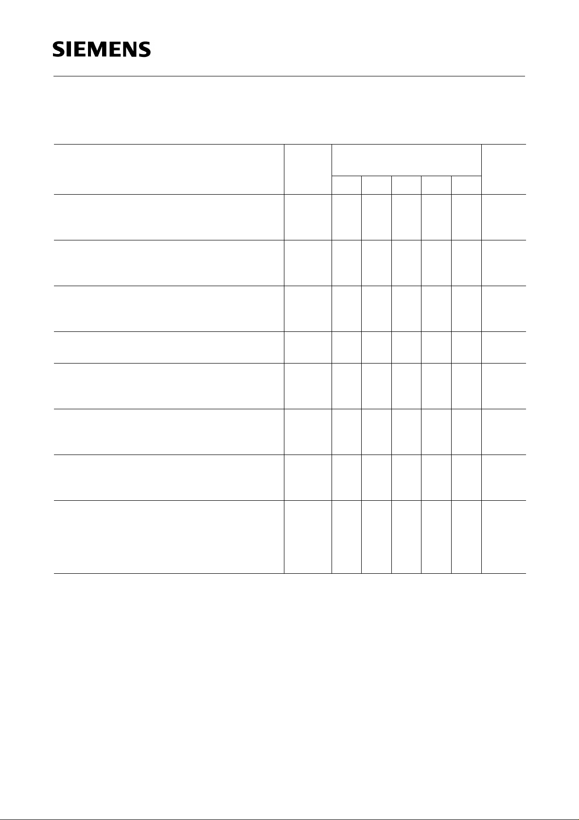
Kennwerte (TA = 25 ˚C)
Characteristics
LOG T671, LSG T671
Bezeichnung
Parameter
Wellenlänge des emittierten Lichtes (typ.)
Wavelength at peak emission (typ.)
I
= 10 mA
F
Dominantwellenlänge (typ.)
Dominant wavelength (typ.)
I
= 10 mA
F
Spektrale Bandbreite bei 50 %
Spectral bandwidth at 50 % I
I
= 10 mA
F
Abstrahlwinkel bei 50 %
Viewing angle at 50 % I
I
v
I
rel max
rel max
(Vollwinkel)
v
(typ.)
(typ.)
Durchlaßspannung (typ.)
Forward voltage (max.)
I
= 10 mA
F
Sperrstrom (typ.)
Reverse current (max.)
V
= 5 V
R
Kapazität (typ.)
Capacitance
V
= 0 V, f = 1 MHz
R
Schaltzeiten:
Switching times:
I
from 10 % to 90 % (typ.)
V
I
from 90 % to 10 % (typ.)
V
I
= 100 mA, tp = 10 µs, RL= 50 Ω
F
Symbol
Symbol
Werte
Values
Einheit
Unit
LS LO LY LG LP
λ
λ
peak
dom
635 610 586 565 557 nm
628 605 590 570 560 nm
∆λ 45 40 45 25 22 nm
2ϕ 120 120 120 120 120 Grad
deg.
V
V
I
I
C
t
t
F
F
R
R
0
r
f
2.0
2.6
2.0
2.6
2.0
2.6
2.0
2.6
2.0
2.6VV
0.01100.01100.01100.01100.0110µA
µA
128 101515pF
300
150
300
150
300
150
450
200
450
200nsns
Semiconductor Group 3
Page 4

LOG T671, LSG T671
Relative spektrale Emission I
= f (λ), TA= 25 ˚C, IF= 10 mA
rel
Relative spectral emission
V(λ) = spektrale Augenempfindlichkeit
Standard eye response curve
Abstrahlcharakteristik I
Radiation characteristic
= f (ϕ)
rel
Semiconductor Group 4
Page 5

LOG T671, LSG T671
Durchlaßstrom IF = f (VF)
Forward current
T
= 25 ˚C
A
Relative Lichtstärke IV/I
V(10 mA)
Relative luminous intensity
T
= 25 ˚C
A
= f (IF)
Zulässige Impulsbelastbarkeit
I
= f (tp)
F
Permissible pulse handling capability
Duty cycle D = parameter, TA = 25 ˚C
Maximal zulässiger Durchlaßstrom
Max. permissible forward current
I
= f (TA)
F
Semiconductor Group 5
Page 6

LOG T671, LSG T671
Wellenlänge der Strahlung λ
Wavelength at peak emission
I
= 10 mA
F
peak
= f (TA)
Dominantwellenlänge λ
Dominant wavelength
I
= 10 mA
F
dom
= f (TA)
Durchlaßspannung
Forward voltage
I
= 10 mA
F
V
= f (TA)
F
Relative Lichtstärke
I
/ I
V
V(25 ˚C )
Relative luminous intensity
I
= 10 mA
F
= f (TA)
Semiconductor Group 6
Page 7

Maßzeichnung (Maße in mm, wenn nicht anders angegeben)
Package Outlines (Dimensions in mm, unless otherwise specified)
LOG T671, LSG T671
L S G T671
LED Emission color 1 Emission color 2 Package
cathode: pin 1 cathode: pin 3
Kathodenkennung: abgeschrägte Ecke
Cathode mark: bevelled edge
GPL06837
Semiconductor Group 7
 Loading...