

Page 1
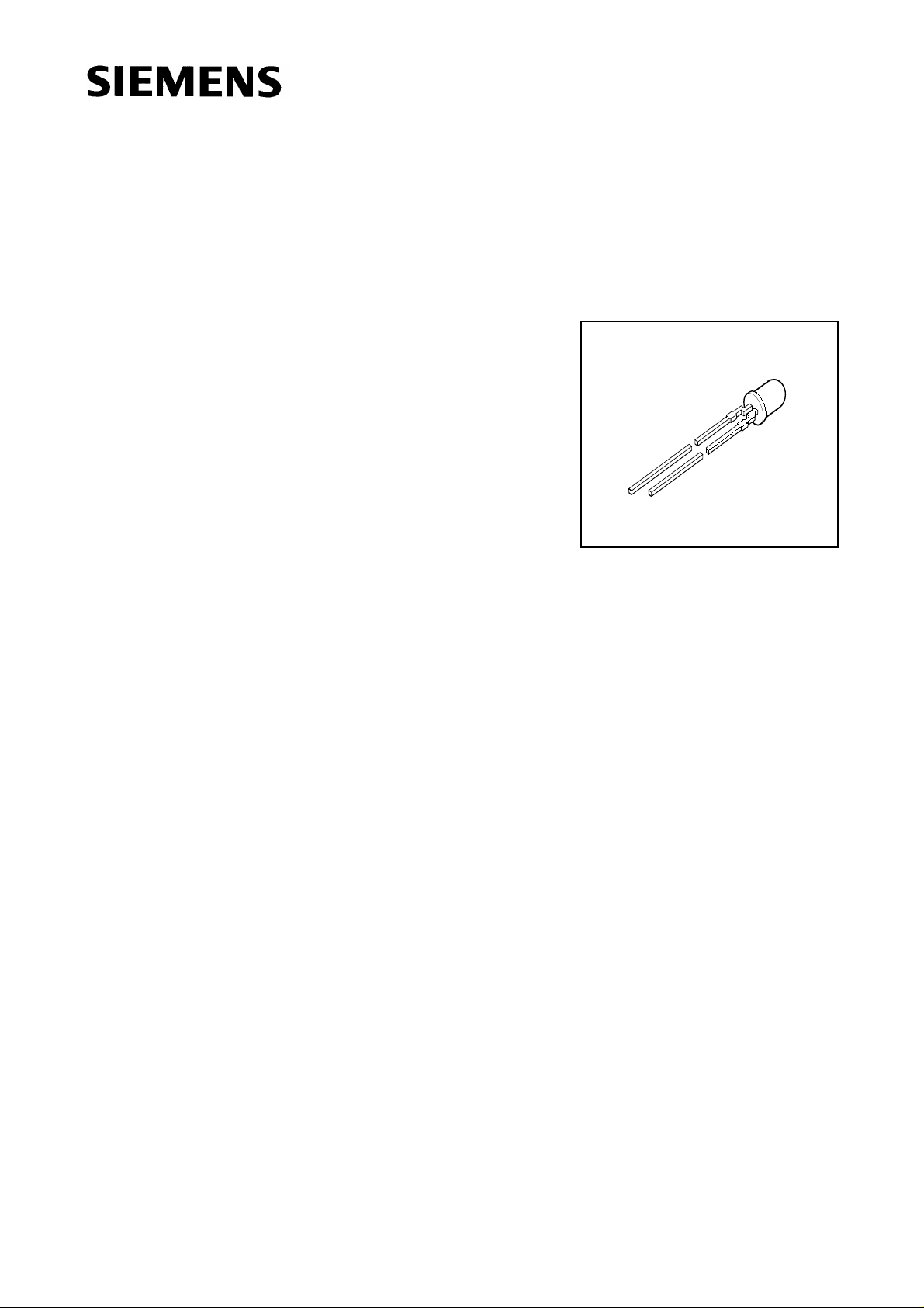
Hyper 3 mm (T1) LED, Diffused
Hyper-Bright, Wide-Angle LED
Besondere Merkmale
● eingefärbtes, diffuses Gehäuse
● zur Einkopplung in Lichtleiter
● als optischer Indikator einsetzbar
● Lötspieße mit Aufsetzebene
● gegurtet lieferbar
● Störimpulsfest nach DIN 40839
Features
● colored, diffused package
● optical coupling into light pipes
● for use as optical indicator
● solder leads with stand-off
● available taped on reel
● load dump resistant acc. to DIN 40839
LS 3386, LA 3386, LO 3386
LY 3386
Semiconductor Group 1 1998-09-18
Page 2
LS 3386, LA 3386, LO 3386, LY 3386
Typ
Type
LS 3386-LP
LS 3386-M
LS 3386-N
LS 3386-P
LS 3386-MQ
LA 3386-MQ
LA 3386-N
LA 3386-P
LA 3386-Q
LA 3386-NR
LO 3386-MQ
LO 3386-N
LO 3386-P
LO 3386-Q
LO 3386-NR
Emissionsfarbe
Color of
Emission
Gehäusefarbe
Color of
Package
Lichtstärke
Luminous
Intensity
I
= 20 mA
F
I
(mcd)
V
super-red red diffused 10 ... 80
16 ... 32
25 ... 50
40 … 80
16 … 125
amber orange diffused 16 … 125
25 … 50
40 … 80
63 … 125
25 … 200
orange orange diffused 16 … 125
25 … 50
40 … 80
63 … 125
25 … 200
Bestellnummer
Ordering Code
Q62703-Q3579
Q62703-Q3581
Q62703-Q3582
Q62703-Q3709
Q62703-Q3580
Q62703-Q3886
Q62703-Q3887
Q62703-Q3888
Q62703-Q3889
Q62703-Q3890
Q62703-Q3891
Q62703-Q3892
Q62703-Q3893
Q62703-Q3894
Q62703-Q3895
LY 3386-MQ
yellow yellow diffused 16 … 125
LY 3386-N
LY 3386-P
LY 3386-Q
LY 3386-NR
Streuung der Lichtstärke in einer Verpackungseinheit I
Luminous intensity ratio in one packaging unit I
V max
/ I
V max
V min
25 … 50
40 … 80
63 … 125
25 … 200
/ I
V min
≤ 2.0.
Q62703-Q3896
Q62703-Q3897
Q62703-Q3898
Q62703-Q3899
Q62703-Q3900
≤ 2.0.
Semiconductor Group 2 1998-09-18
Page 3
Grenzwerte
Maximum Ratings
LS 3386, LA 3386, LO 3386, LY 3386
Bezeichnung
Parameter
Betriebstemperatur
Operating temperature range
Lagertemperatur
Storage temperature range
Sperrschichttemperatur
Junction temperature
Durchlaßstrom
Forward current
Stoßstrom
Surge current
t ≤ 10 µs, D = 0.005
Sperrspanung
Reverse voltage
Verlustleistung
Power dissipation
T
≤ 25 ˚C
A
Wärmewiderstand
Thermal resistance
Sperrschicht / Umgebung
Junction / air
1)
1)
Symbol
Symbol
T
op
T
stg
T
j
I
F
I
FM
V
R
P
tot
R
th JA
Werte
Values
Einheit
Unit
LS, LO, LA LY
– 55... + 100 ˚C
– 55... + 100 ˚C
+ 100 ˚C
30 20 mA
1 0.2 A
3V
80 55 mW
500 K/W
1)
Belastung in Sperrichtung sollte vermieden werden.
1)
Reverse biasing should be avoided.
Semiconductor Group 3 1998-09-18
Page 4

Kennwerte (TA = 25 ˚C)
Characteristics
LS 3386, LA 3386, LO 3386, LY 3386
Bezeichnung
Parameter
Wellenlänge des emittierten Lichtes (typ.)
Wavelength at peak emission (typ.)
I
= 20 mA
F
Dominantwellenlänge (typ.)
Dominant wavelength (typ.)
I
= 20 mA
F
Spektrale Bandbreite bei 50% I
Spectral bandwidth at 50% I
I
= 20 mA
F
rel max
rel max
(typ.)
(typ.)
Abstrahlwinkel bei 50% Iv (Vollwinkel)
Viewing angle at 50% I
v
Durchlaßspannung (typ.)
Forward voltage (max.)
I
= 20 mA
F
Sperrstrom (typ.)
Reverse current (max.)
V
= 3 V
R
Temperaturkoeffizient von λ
Temperature coefficient of λ
Temperaturkoeffizient von λ
dom(IF
dom(IF
,
peak
= 20 mA)
= 20 mA)
IF = 20 mA (typ.)
Temperature coefficient of λ
peak
,
IF = 20 mA (typ.)
Symbol
Symbol
Werte
Values
Einheit
Unit
LS LA LO LY
λ
λ
peak
dom
645 622 610 591 nm
632 615 605 587 nm
∆λ 16 16 16 15 nm
2ϕ 100 100 100 100 Grad
deg.
V
V
I
R
I
R
TC
TC
F
F
λ
λ
2.0
2.6
2.0
2.6
2.0
2.6
2.0
2.6
V
V
0.01100.01100.01100.0110µA
µA
0.014 0.062 0.067 0.096 nm/K
0.14 0.13 0.13 0.13 nm/K
Temperaturkoeffizient von VF, IF = 20 mA (typ.)
TC
V
– 1.95 – 1.78 – 1.67 – 2.51 mV/K
Temperature coefficient of VF, IF = 20 mA (typ.)
Semiconductor Group 4 1998-09-18
Page 5

LS 3386, LA 3386, LO 3386, LY 3386
Relative spektrale Emission I
= f (λ), TA= 25 ˚C, IF= 20 mA
rel
Relative spectral emission
V (λ) = spektrale Augenempfindlichkeit
Standard eye response curve
100
%
Ι
rel
80
60
40
20
OHL00235
V
λ
yellow
orange
amber
super-red
0
400
450 500 550 600 650 700nm
Abstrahlcharakteristik
Radiation characteristic
50
60
70
80
I
rel
= f (ϕ)
λ
0102040 30
φ
1.0
0.8
0.6
0.4
0.2
OHL01681
90
100
1.0 0.8 0.6 0.4
0
02040 60 80 100 120
Semiconductor Group 5 1998-09-18
Page 6

LS 3386, LA 3386, LO 3386, LY 3386
Durchlaßstrom IF = f (VF)
Forward current
T
= 25˚C
A
2
10
mA
Ι
5
F
1
10
5
0
10
5
-1
10
1.4 1.8 2.2 2.6 3.0 V 3.4
1.0
OHL00232
V
F
Maximal zulässiger Durchlaßstrom
Max. permissible forward current
I
= f (TA)
F
35
mA
Ι
F
30
25
yellow
20
15
10
5
0
0 20 40 60 80 C 100
OHL00248
Τ
A
Relative Lichtstärke IV/I
V(20 mA)
Relative luminous intensity
T
= 25˚C
A
1
10
Ι
V
Ι
V
(20 mA)
0
10
5
-1
10
5
superred
yellow
orange/amber
10
-2
5
-3
10
10
-1
0
10
55mA
= f (IF)
1
10
OHL00233
10
Ι
F
Relative Lichtstärke IV/ I
V(25˚C )
= f (TA)
Relative luminous intensity
I
= 20 mA
F
OHL00238
Ι
V
Ι
V
(25 C)
2.0
1.6
orange
yellow
amber
super-red
1.2
0.8
orange
0.4
2
0
-20 0 20 40 60 C 100
yellow
amber
super-red
T
A
Semiconductor Group 6 1998-09-18
Page 7

LS 3386, LA 3386, LO 3386, LY 3386
Zulässige Impulsbelastbarkeit IF = f (tp)
Permissible pulse handling capability
LS, LA, LO
Duty cycle D = parameter, TA = 25 ˚C
=
T
OHL00322
Ι
F
1
10
A
Ι
5
F
=
D
t
p
t
p
T
D
10
0
5
0.005
0.01
0.02
0.05
0.1
0.2
0.5
-1
10
5
Zulässige Impulsbelastbarkeit IF = f (tp)
Permissible pulse handling capability
LY
Duty cycle D = parameter, TA = 25 ˚C
=
T
OHL00316
Ι
F
0
10
A
Ι
F
5
=
D
t
p
t
p
T
D
0.005
0.01
0.02
0.05
10
0.1
-1
0.2
5
0.5
10
-2
-5
10
-410-310-210-1100101102
10s
t
p
10
-2
-5
10
-410-310-210-1100101102
Maßzeichnung (Maße in mm, wenn nicht anders angegeben)
Package Outlines (Dimensions in mm, unless otherwise specified)
spacing
2.54 mm
Collector/
Cathode
Area not flat
0.7
0.4
0.6
1.8
1.2
29.0
27.0
0.4
0.8
0.4
1.1
0.9
4.8
4.4
6.1
5.7
3.7
3.5
2.7
2.1
ø2.7
ø2.9
Chip position
3.4
3.1
GEX06710
0.6
0.4
10s
t
p
Kathodenkennzeichnung: Kürzerer Lötspieß
Cathode mark: Short solder lead
Semiconductor Group 7 1998-09-18
 Loading...