

Page 1
查询LMP7718MME供应商
LMP7717/LMP7718
88 MHz, Precision, Low Noise, 1.8V CMOS Input,
Decompensated Operational Amplifier
November 6, 2007
LMP7717/LMP7718 88 MHz, Precision, Low Noise, 1.8V CMOS Input, Decompensated
Operational Amplifier
General Description
The LMP7717 (single) and the LMP7718 (dual) low noise,
CMOS input operational amplifiers offer a low input voltage
noise density of 5.8 nV/
(LMP7717) of quiescent current. The LMP7717/LMP7718 are
stable at a gain of 10 and have a gain bandwidth (GBW)
product of 88 MHz. The LMP7717/LMP7718 have a supply
voltage range of 1.8V to 5.5V and can operate from a single
supply. The LMP7717/LMP7718 each feature a rail-to-rail
output stage. Both amplifiers are part of the LMP® precision
amplifier family and are ideal for a variety of instrumentation
applications.
The LMP7717 family provides optimal performance in low
voltage and low noise systems. A CMOS input stage, with
typical input bias currents in the range of a few femto-Amperes, and an input common mode voltage range, which
includes ground, make the LMP7717/LMP7718 ideal for low
power sensor applications where high speeds are needed.
The LMP7717/LMP7718 are manufactured using National’s
advanced VIP50 process. The LMP7717 is offered in either a
5-Pin SOT23 or an 8-Pin SOIC package. The LMP7718 is
offered in either the 8-Pin SOIC or the 8-Pin MSOP.
while consuming only 1.15 mA
Features
(Typical 5V supply, unless otherwise noted)
Input offset voltage ±150 µV (max)
■
Input referred voltage noise 5.8 nV/√Hz
■
Input bias current 100 fA
■
Gain bandwidth product 88 MHz
■
Supply voltage range 1.8V to 5.5V
■
Supply current per channel
■
LMP7717 1.15 mA
—
LMP7718 1.30 mA
—
Rail-to-Rail output swing
■
@ 10 kΩ load 25 mV from rail
—
@ 2 kΩ load 45 mV from rail
—
Guaranteed 2.5V and 5.0V performance
■
Total harmonic distortion 0.04% @1 kHz, 600Ω
■
Temperature range −40°C to 125°C
■
Applications
ADC interface
■
Photodiode amplifiers
■
Active filters and buffers
■
Low noise signal processing
■
Medical instrumentation
■
Sensor interface applications
■
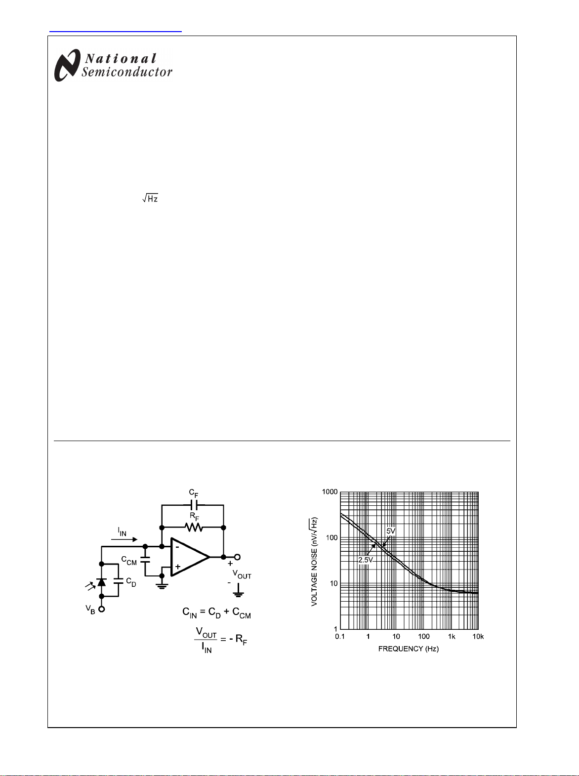
Typical Application
Photodiode Transimpedance Amplifier
LMP® is a registered trademark of National Semiconductor Corporation.
© 2007 National Semiconductor Corporation 300108 www.national.com
30010869
Input Referred Voltage Noise vs. Frequency
30010839
Page 2

Absolute Maximum Ratings (Note 1)
If Military/Aerospace specified devices are required,
please contact the National Semiconductor Sales Office/
Distributors for availability and specifications.
ESD Tolerance (Note 2)
Human Body Model 2000V
LMP7717/LMP7718
Machine Model 200V
VIN Differential
Supply Voltage (V+ – V−)
Input/Output Pin Voltage V+ +0.3V, V− −0.3V
Storage Temperature Range −65°C to 150°C
Junction Temperature (Note 3) +150°C
±0.3V
6.0V
Soldering Information
Infrared or Convection (20 sec) 235°C
Wave Soldering Lead Temp (10 sec) 260°C
Operating Ratings (Note 1)
Temperature Range (Note 3) −40°C to 125°C
Supply Voltage (V+ – V−)
−40°C ≤ TA ≤ 125°C
0°C ≤ TA ≤ 125°C
Package Thermal Resistance (θJA (Note 3))
5-Pin SOT23 180°C/W
8-Pin SOIC 190°C/W
8-Pin MSOP 236°C/W
2.5V Electrical Characteristics (Note 4)
Unless otherwise specified, all limits are guaranteed for TA = 25°C, V+ = 2.5V, V− = 0V, VCM = V+/2 = VO. Boldface limits apply at
the temperature extremes.
Symbol Parameter Conditions Min
(Note 6)
V
OS
TC VOSInput Offset Average Drift
I
B
I
OS
CMRR Common Mode Rejection Ratio
PSRR Power Supply Rejection Ratio
CMVR Input Common-Mode Voltage
A
VOL
V
OUT
Input Offset Voltage ±20 ±180
LMP7717 −1.0
(Note 7)
Input Bias Current VCM = 1.0V
Input Offset Current VCM = 1.0V
Range
Open Loop Gain V
Output Swing High
Output Swing Low
LMP7718 −1.8
−40°C ≤ TA ≤ 85°C
(Notes 8, 9)
−40°C ≤ TA ≤ 125°C
(Note 9)
0V ≤ VCM ≤ 1.4V
2.0V ≤ V+ ≤ 5.5V, VCM = 0V
1.8V ≤ V+ ≤ 5.5V, VCM = 0V
CMRR ≥ 60 dB
CMRR ≥ 55 dB
= 0.15V to 2.2V,
OUT
RL = 2 kΩ to V+/2
V
= 0.15V to 2.2V,
OUT
RL = 10 kΩ to V+/2
RL = 2 kΩ to V+/2
RL = 10 kΩ to V+/2
RL = 2 kΩ to V+/2
RL = 10 kΩ to V+/2
LMP7717 88
LMP7718 84
LMP7717 92
LMP7718 90
83
80
85
80
85 98
−0.3
−0.3
82
80
88
86
0.05 1
0.05 1
.006 0.5
25 70
20 60
30 70
15 60
Typ
(Note 5)
94
100
1.5
98
92
110
95
Max
(Note 6)
±480
±4
25
100
50
1.5
77
66
73
62
2.0V to 5.5V
1.8V to 5.5V
Units
µV
μV/°C
pA
pA
dB
dB
V
dB
mV from
rail
www.national.com 2
Page 3

LMP7717/LMP7718
I
OUT
I
S
Output Short Circuit Current Sourcing to V
VIN = 200 mV (Note 10)
Sinking to V
VIN = –200 mV (Note 10)
Supply Current per Amplifier LMP7717 0.95 1.30
−
36
47
30
+
7.5
15
5
1.65
LMP7718 per channel 1.1 1.5
1.85
SR Slew Rate AV = +10, Rising (10% to 90%)
AV = +10, Falling (90% to 10%)
GBWP Gain Bandwidth Product
e
n
i
n
Input-Referred Voltage Noise f = 1 kHz 6.2
Input-Referred Current Noise f = 1 kHz 0.01
THD+N Total Harmonic Distortion +
AV = +10, RL = 10 kΩ
f = 1 kHz, AV = 1, RL = 600Ω
0.01 %
32
24
88 MHz
Noise
5V Electrical Characteristics (Note 4)
Unless otherwise specified, all limits are guaranteed for TA = 25°C, V+ = 5V, V− = 0V, VCM = V+/2 = VO. Boldface limits apply at
the temperature extremes.
Symbol Parameter Conditions Min
(Note 6)
V
OS
TC VOSInput Offset Average Drift
I
B
Input Offset Voltage ±10 ±150
LMP7717 −1.0
(Note 7)
Input Bias Current VCM = 2.0V
LMP7718 −1.8
−40°C ≤ TA ≤ 85°C
(Notes 8, 9)
−40°C ≤ TA ≤ 125°C
I
OS
Input Offset Current VCM = 2.0V
(Note 9)
CMRR Common Mode Rejection Ratio
0V ≤ VCM ≤ 3.7V
85
80
PSRR Power Supply Rejection Ratio
2.0V ≤ V+ ≤ 5.5V, VCM = 0V
85
80
85 98
−0.3
−0.3
82
CMVR Input Common-Mode Voltage
Range
A
VOL
Open Loop Gain V
1.8V ≤ V+ ≤ 5.5V, VCM = 0V
CMRR ≥ 60 dB
CMRR ≥ 55 dB
= 0.3V to 4.7V,
OUT
RL = 2 kΩ to V+/2
LMP7717 88
LMP7718 84
80
V
= 0.3V to 4.7V,
OUT
RL = 10 kΩ to V+/2
LMP7717 92
88
LMP7718 90
86
0.1 1
0.1 1
.01 0.5
Typ
(Note 5)
100
100
4
107
90
110
95
Max
(Note 6)
±450
±4
25
100
50
4
mA
mA
V/μs
nV/
pA/
Units
µV
μV/°C
pA
pA
dB
dB
V
dB
3 www.national.com
Page 4

V
OUT
Output Swing High
RL = 2 kΩ to V+/2
LMP7717 35 70
LMP7718 45 80
25 60
LMP7717/LMP7718
Output Swing Low
RL = 10 kΩ to V+/2
RL = 2 kΩ to V+/2
LMP7717 42 70
LMP7718 50 80
25 60
46
60
38
10.5
21
6.5
I
OUT
I
S
RL = 10 kΩ to V+/2
Output Short Circuit Current Sourcing to V
−
VIN = 200 mV (Note 10)
Sinking to V
+
VIN = –200 mV (Note 10)
Supply Current per Amplifier LMP7717 1.15 1.40
LMP7718 per channel 1.30 1.70
SR Slew Rate AV = +10, Rising (10% to 90%) 35
AV = +10, Falling (90% to 10%) 28
GBWP Gain Bandwidth Product
e
n
i
n
Input-Referred Voltage Noise f = 1 kHz 5.8
Input-Referred Current Noise f = 1 kHz 0.01
THD+N Total Harmonic Distortion +
AV = +10, RL = 10 kΩ
f = 1 kHz, AV = 1, RL = 600Ω
88 MHz
0.01 %
Noise
77
77
66
73
78
66
1.75
2.05
mV from
rail
mA
mA
V/μs
nV/
pA/
Note 1: Absolute Maximum Ratings indicate limits beyond which damage to the device may occur. Operating Ratings indicate conditions for which the device is
intended to be functional, but specific performance is not guaranteed. For guaranteed specifications and the test conditions, see the Electrical Characteristics
Tables.
Note 2: Human Body Model, applicable std. MIL-STD-883, Method 3015.7. Machine Model, applicable std. JESD22-A115-A (ESD MM std. of JEDEC)
Field-Induced Charge-Device Model, applicable std. JESD22-C101-C (ESD FICDM std. of JEDEC).
Note 3: The maximum power dissipation is a function of T
PD = (T
Note 4: Electrical Table values apply only for factory testing conditions at the temperature indicated. Factory testing conditions result in very limited self-heating
of the device such that TJ = TA. No guarantee of parametric performance is indicated in the electrical tables under conditions of internal self-heating where TJ >
TA.
Note 5: Typical values represent the most likely parametric norm as determined at the time of characterization. Actual typical values may vary over time and will
also depend on the application and configuration. The typical values are not tested and are not guaranteed on shipped production material.
Note 6: Limits are 100% production tested at 25°C. Limits over the operating temperature range are guaranteed through correlations using the statistical quality
control (SQC) method.
Note 7: Offset voltage average drift is determined by dividing the change in VOS by temperature change.
Note 8: Positive current corresponds to current flowing into the device.
Note 9: Input bias current and input offset current are guaranteed by design
Note 10: The short circuit test is a momentary test, the short circuit duration is 1.5 ms.
- TA)/θJA. All numbers apply for packages soldered directly onto a PC Board.
J(MAX)
, θJA. The maximum allowable power dissipation at any ambient temperature is
J(MAX)
www.national.com 4
Page 5
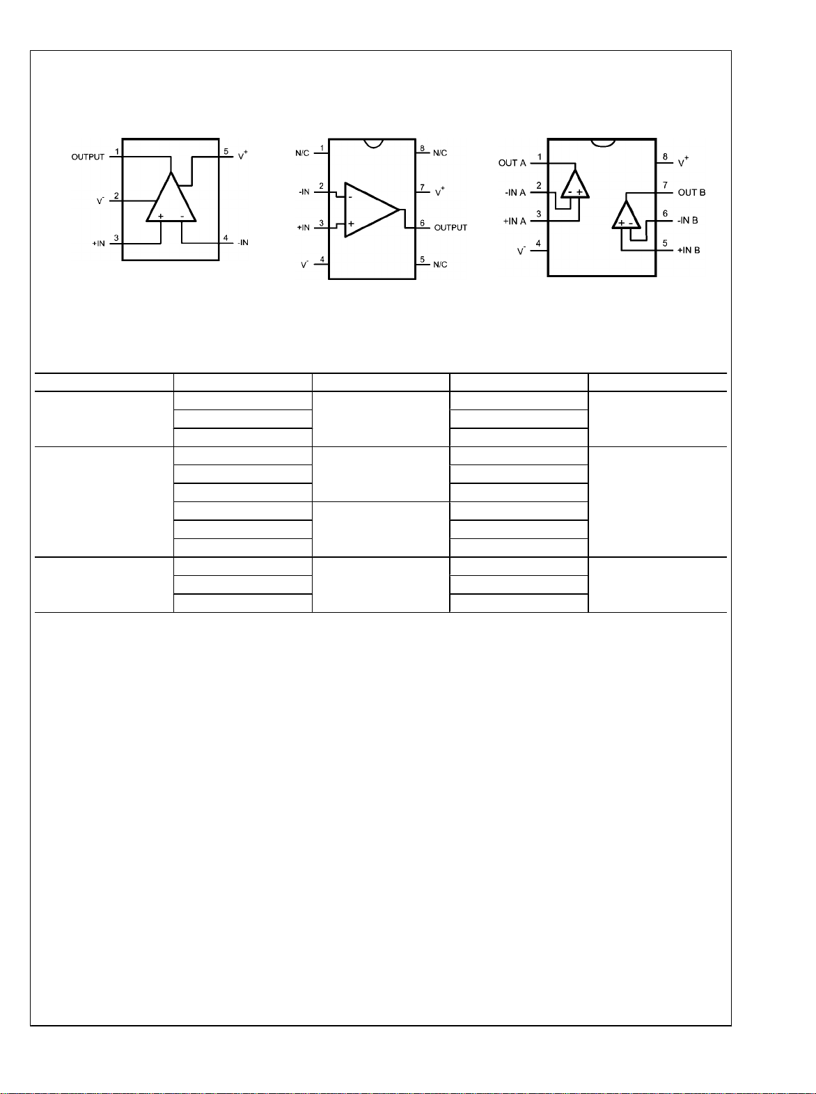
Connection Diagrams
LMP7717/LMP7718
5-Pin SOT23 (LMP7717)
Top View
30010801
8-Pin SOIC (LMP7717)
Top View
8-Pin SOIC/MSOP (LMP7718)
30010885
Ordering Information
Package Part Number Package Marking Transport Media NSC Drawing
5-Pin SOT23
8-Pin SOIC
8-Pin MSOP
LMP7717MF
AT4A
LMP7717MFX 3k Units Tape and Reel
LMP7717MA
LMP7717MAE 250 Units Tape and Reel
LMP7717MAX 2.5k Units Tape and Reel
LMP7718MA
LMP7718MAE 250 Units Tape and Reel
LMP7718MAX 2.5k Units Tape and Reel
LMP7718MM
LMP7718MMX 3.5k Units Tape and Reel
LMP7717MA
LMP7718MA
AP4A
1k Units Tape and Reel
95 Units/Rail
95 Units/Rail
1k Units Tape and Reel
30010802
MF05ALMP7717MFE 250 Units Tape and Reel
M08A
MUA08ALMP7718MME 250 Units Tape and Reel
5 www.national.com
Page 6

Typical Performance Characteristics Unless otherwise specified, T
VS = V+ - V−, VCM = VS/2.
= 25°C, V– = 0, V+ = 5V,
A
TCVOS Distribution (LMP7717)
LMP7717/LMP7718
TCVOS Distribution (LMP7717)
30010890
Offset Voltage Distribution
30010891
Offset Voltage Distribution
30010892
Supply Current vs. Supply Voltage (LMP7717)
30010805
www.national.com 6
VOS vs. V
30010893
CM
30010809
Page 7

LMP7717/LMP7718
VOS vs. V
CM
VOS vs. Supply Voltage
30010851
VOS vs. V
CM
Slew Rate vs. Supply Voltage
30010811
Input Bias Current vs. V
CM
30010812
30010862
Input Bias Current vs. V
30010852
CM
30010887
7 www.national.com
Page 8
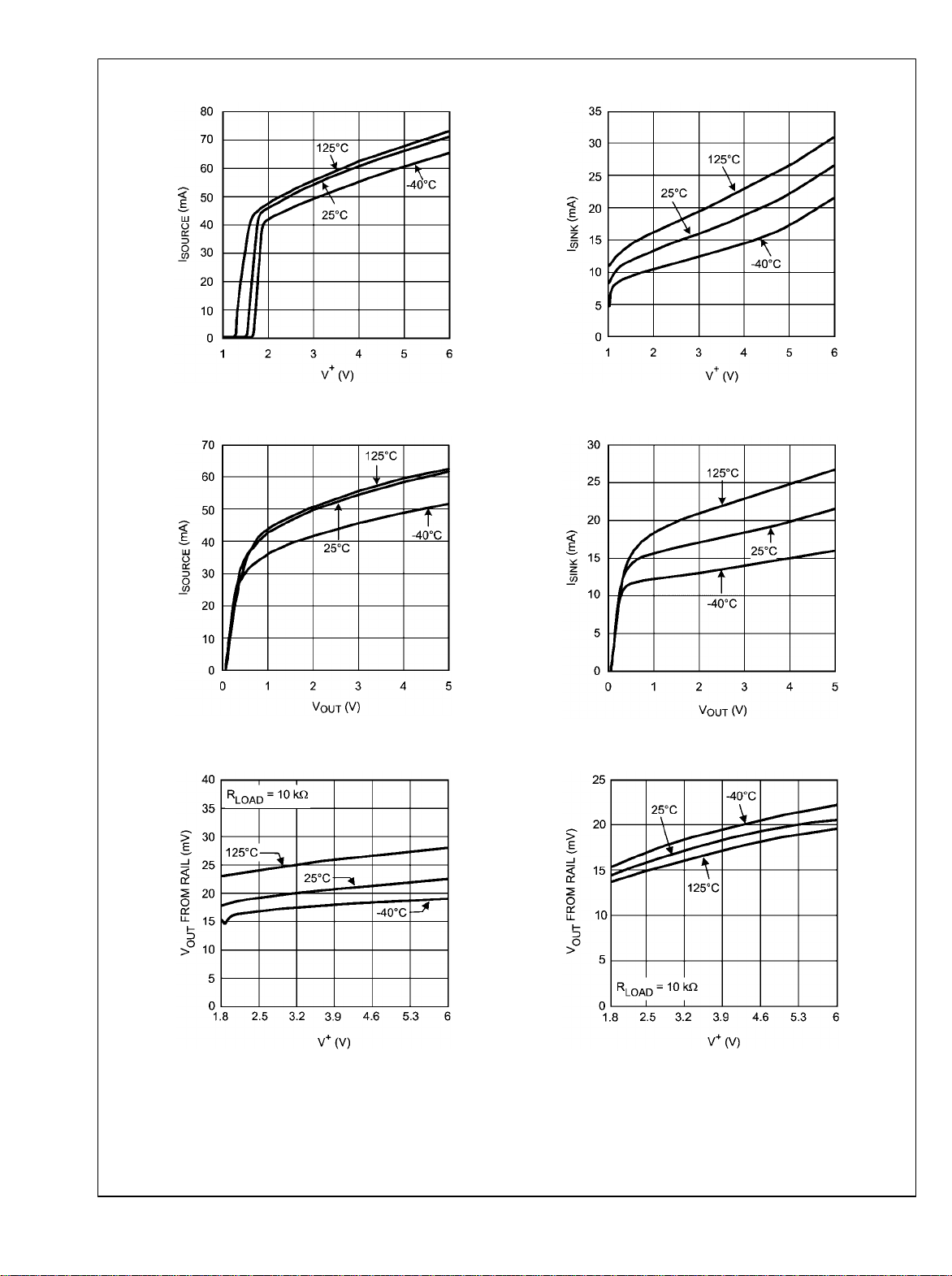
Sourcing Current vs. Supply Voltage
LMP7717/LMP7718
Sinking Current vs. Supply Voltage
30010820
Sourcing Current vs. Output Voltage
30010850
Positive Output Swing vs. Supply Voltage
30010819
Sinking Current vs. Output Voltage
30010854
Negative Output Swing vs. Supply Voltage
30010817
www.national.com 8
30010815
Page 9

LMP7717/LMP7718
Positive Output Swing vs. Supply Voltage
30010816
Positive Output Swing vs. Supply Voltage
Negative Output Swing vs. Supply Voltage
30010814
Negative Output Swing vs. Supply Voltage
30010818
Input Referred Voltage Noise vs. Frequency
30010839
Overshoot and Undershoot vs. C
30010813
LOAD
30010830
9 www.national.com
Page 10

LMP7717/LMP7718
THD+N vs. Frequency
THD+N vs. Frequency
THD+N vs. Peak-to-Peak Output Voltage (V
30010874
Open Loop Gain and Phase
30010826
OUT
30010804
)
THD+N vs. Peak-to-Peak Output Voltage (V
30010875
OUT
)
Closed Loop Output Impedance vs. Frequency
30010806
www.national.com 10
30010832
Page 11

LMP7717/LMP7718
Crosstalk Rejection
30010880
Large Signal Transient Response, AV = +10
Small Signal Transient Response, AV = +10
30010853
Small Signal Transient Response, AV = +10
30010855
Large Signal Transient Response, AV = +10
30010863
30010857
PSRR vs. Frequency
30010870
11 www.national.com
Page 12

LMP7717/LMP7718
CMRR vs. Frequency
Input Common Mode Capacitance vs. V
CM
30010856
30010876
www.national.com 12
Page 13

LMP7717/LMP7718
Application Information
ADVANTAGES OF THE LMP7717/LMP7718
Wide Bandwidth at Low Supply Current
The LMP7717/LMP7718 are high performance op amps that
provide a GBW of 88 MHz with a gain of 10 while drawing a
low supply current of 1.15 mA. This makes them ideal for providing wideband amplification in data acquisition applications.
With the proper external compensation the LMP7717 can be
operated at gains of ±1 and still maintain much faster slew
rates than comparable unity gain stable amplifiers. The increase in bandwidth and slew rate is obtained without any
additional power consumption over the LMP7715.
Low Input Referred Noise and Low Input Bias Current
The LMP7717/LMP7718 have a very low input referred voltage noise density (5.8 nV/
ensures a small input bias current (100 fA) and low input referred current noise (0.01 pA/ ). This is very helpful in
maintaining signal integrity, and makes the LMP7717/
LMP7718 ideal for audio and sensor based applications.
Low Supply Voltage
The LMP7717 and the LMP7718 have performance guaranteed at 2.5V and 5V supply. These parts are guaranteed to
be operational at all supply voltages between 2.0V and 5.5V,
for ambient temperatures ranging from −40°C to 125°C, thus
utilizing the entire battery lifetime. The LMP7717/LMP7718
are also guaranteed to be operational at 1.8V supply voltage,
for temperatures between 0°C and 125°C optimizing their usage in low-voltage applications.
at 1 kHz). A CMOS input stage
The LMP7717/LMP7718 require a gain of ±10 to be stable.
However, with an external compensation network (a simple
RC network) these parts can be stable with gains of ±1 and
still maintain the higher slew rate. Looking at the Bode plots
for the LMP7717 and its closest equivalent unity gain stable
op amp, the LMP7715, one can clearly see the increased
bandwidth of the LMP7717. Both plots are taken with a parallel combination of 20 pF and 10 kΩ for the output load.
30010822
FIGURE 1. LMP7717 A
vs. Frequency
VOL
RRO and Ground Sensing
Rail-to-Rail output swing provides the maximum possible dynamic range. This is particularly important when operating at
low supply voltages. An innovative positive feedback scheme
is used to boost the current drive capability of the output
stage. This allows the LMP7717/LMP7718 to source more
than 40 mA of current at 1.8V supply. This also limits the performance of the these parts as comparators, and hence the
usage of the LMP7717 and the LMP7718 in an open-loop
configuration is not recommended. The input common-mode
range includes the negative supply rail which allows direct
sensing at ground in single supply operation.
Small Size
The small footprints of the LMP7717 packages and the
LMP7718 packages save space on printed circuit boards, and
enable the design of smaller electronic products, such as cellular phones, pagers, or other portable systems. Long traces
between the signal source and the op amp make the signal
path more susceptible to noise pick up.
The physically smaller LMP7717 or LMP7718 packages allow
the op amp to be placed closer to the signal source, thus reducing noise pickup and maintaining signal integrity.
USING THE DECOMPENSATED LMP7717
Advantages of Decompensated Op Amp
A unity gain stable op amp, which is fully compensated, is
designed to operate with good stability down to gains of ±1.
The large amount of compensation does provide an op amp
that is relatively easy to use; however, a decompensated op
amp is designed to maximize the bandwidth and slew rate
without any additional power consumption. This can be very
advantageous.
30010823
FIGURE 2. LMP7715 A
vs. Frequency
VOL
Figure 1 shows the much larger 88 MHz bandwidth of the
LMP7717 as compared to the 17 MHz bandwidth of the
LMP7715 shown in Figure 2. The decompensated LMP7717
has five times the bandwidth of the LMP7715.
What is a Decompensated Op Amp?
The differences between the unity gain stable op amp and the
decompensated op amp are shown in Figure 3. This Bode plot
assumes an ideal two pole system. The dominant pole of the
decompensated op amp is at a higher frequency, f1, as compared to the unity gain stable op amp which is at fd as shown
in Figure 3. This is done in order to increase the speed capability of the op amp while maintaining the same power dissipation of the unity gain stable op amp. The LMP7717/
LMP7718 have a dominant pole at 8.6 Hz. The unity gain stable LMP7715/LMP7716 have their dominant pole at 1.6 Hz.
13 www.national.com
Page 14

LMP7717/LMP7718
30010825
30010824
FIGURE 3. Open Loop Gain for Unity Gain Stable Op Amp
and Decompensated Op Amp
Having a higher frequency for the dominate pole will result in:
1.
The DC open loop gain (A
frequency.
2.
A wider closed loop bandwidth.
3.
Better slew rate due to reduced compensation
) extending to a higher
VOL
capacitance within the op amp.
The second open loop pole (f2) for the LMP7717/LMP7718
occurs at 45 MHz. The unity gain (fu’) occurs after the second
pole at 51 MHz. An ideal two pole system would give a phase
margin of 45° at the location of the second pole. The
LMP7717/LMP7718 have parasitic poles close to the second
pole, giving a phase margin closer to 0°. Therefore it is necessary to operate the LMP7717/LMP7718 at a closed loop
gain of 10 or higher, or to add external compensation in order
to assure stability.
For the LMP7715, the gain bandwidth product occurs at 17
MHz. The curve is constant from fd to fu which occurs before
the second pole.
For the LMP7717/LMP7718 the GBW = 88 MHz and is constant between f1 and f2. The second pole at f2 occurs before
A
=1. Therefore fu’ occurs at 51 MHz, well before the GBW
VOL
frequency of 88 MHz. For decompensated op amps the unity
gain frequency and the GBW are no longer equal. G
minimum gain for stability and for the LMP7717/LMP7718 this
min
is the
is a gain of 10 or 20 dB.
FIGURE 4. LMP7717 with Lead-Lag Compensation for
Inverting Configuration
To cover how to calculate the compensation network values
it is necessary to introduce the term called the feedback factor
or F. The feedback factor F is the feedback voltage VA-V
across the op amp input terminals relative to the op amp output voltage V
OUT
.
From feedback theory the classic form of the feedback equation for op amps is:
A is the open loop gain of the amplifier and AF is the loop gain.
Both are highly important in analyzing op amps. Normally AF
>>1 and so the above equation reduces to:
Deriving the equations for the lead-lag compensation is beyond the scope of this datasheet. The derivation is based on
the feedback equations that have just been covered. The inverse of feedback factor for the circuit in Figure 4 is:
B
Input Lead-Lag Compensation
The recommended technique which allows the user to compensate the LMP7717/LMP7718 for stable operation at any
gain is lead-lag compensation. The compensation components added to the circuit allow the user to shape the feedback
function to make sure there is sufficient phase margin when
the loop gain is as low as 0 dB and still maintain the advantages over the unity gain op amp. Figure 4 shows the leadlag configuration. Only RC and C are added for the necessary
compensation.
www.national.com 14
(1)
where 1/F's pole is located at
(2)
1/F's zero is located at
(3)
Page 15

(4)
The circuit gain for Figure 4 at low frequencies is −RF/RIN, but
F, the feedback factor is not equal to the circuit gain. The
feedback factor is derived from feedback theory and is the
same for both inverting and non-inverting configurations. Yes,
the feedback factor at low frequencies is equal to the gain for
the non-inverting configuration.
(5)
From this formula, we can see that
•
1/F's zero is located at a lower frequency compared with
1/F's pole.
•
1/F's value at low frequency is 1 + RF/RIN.
•
This method creates one additional pole and one
additional zero.
•
This pole-zero pair will serve two purposes:
To raise the 1/F value at higher frequencies prior to its
—
intercept with A, the open loop gain curve, in order to
meet the G
some overcompensation will be necessary for good
= 10 requirement. For the LMP7717
min
stability.
To achieve the previous purpose above with no
—
additional loop phase delay.
Please note the constraint 1/F ≥ G
only in the vicinity where the open loop gain A and 1/F inter-
needs to be satisfied
min
sect; 1/F can be shaped elsewhere as needed. The 1/F pole
must occur before the intersection with the open loop gain A.
In order to have adequate phase margin, it is desirable to follow these two rules:
Rule 1
1/F and the open loop gain A should intersect at the
frequency where there is a minimum of 45° of phase
margin. When over-compensation is required the intersection point of A and 1/F is set at a frequency
where the phase margin is above 45°, therefore increasing the stability of the circuit.
Rule 2
1/F’s pole should be set at least one decade below
the intersection with the open loop gain A in order to
take advantage of the full 90° of phase lead brought
by 1/F’s pole which is F’s zero. This ensures that the
effect of the zero is fully neutralized when the 1/F and
A plots intersect each other.
Calculating Lead-Lag Compensation for LMP7717
Figure 5 is the same plot as Figure 1, but the A
curves have been redrawn as smooth lines to more readily
and phase
VOL
show the concepts covered, and to clearly show the key parameters used in the calculations for lead-lag compensation.
30010848
FIGURE 5. LMP7717/LMP7718 Simplified Bode Plot
To obtain stable operation with gains under 10 V/V the open
loop gain margin must be reduced at high frequencies to
where there is a 45° phase margin when the gain margin of
the circuit with the external compensation is 0 dB. The pole
and zero in F, the feedback factor, control the gain margin at
the higher frequencies. The distance between F and A
the gain margin; therefore, the unity gain point (0 dB) is where
F crosses the A
VOL
curve.
VOL
is
For the example being used RIN = RF for a gain of −1. Therefore F = 6 dB at low frequencies. At the higher frequencies
the minimum value for F is 18 dB for 45° phase margin. From
Equation 5 we have the following relationship:
Now set RF = RIN = R. With these values and solving for R
we have RC = R/5.9. Note that the value of C does not affect
the ratio between the resistors. Once the value of the resistors
is set, then the position of the pole in F must be set. A 2 kΩ
resistor is used for RF and RIN in this design. Therefore the
value for RC is set at 330Ω, the closest standard value for 2
kΩ/5.9.
Rewriting Equation 2 to solve for the minimum capacitor value
gives the following equation:
C = 1/(2πfpRC)
The feedback factor curve, F, intersects the A
about 12 MHz. Therefore the pole of F should not be any
curve at
VOL
larger than 1.2 MHz. Using this value and RC = 330Ω the
minimum value for C is 390 pF. Figure 6 shows that there is
too much overshoot, but the part is stable. Increasing C to 2.2
nF did not improve the ringing, as shown in Figure 7.
LMP7717/LMP7718
C
15 www.national.com
Page 16

LMP7717/LMP7718
30010803
FIGURE 6. First Try at Compensation, Gain = −1
30010807
FIGURE 7. C Increased to 2.2 nF, Gain = −1
Some over-compensation appears to be needed for the desired overshoot characteristics. Instead of intersecting the
A
curve at 18 dB, 2 dB of over-compensation will be used,
VOL
and the A
tion 5 for 20 dB, or 10 V/V, the closest standard value of R
curve will be intersected at 20 dB. Using Equa-
VOL
is 240Ω. The following two waveforms show the new resistor
value with C = 390 pF and 2.2 nF. Figure 9 shows the final
compensation and a very good response for the 1 MHz
square wave.
30010810
FIGURE 9. RC = 240Ω and C = 2.2 nF, Gain = −1
To summarize, the following steps were taken to compensate
the LMP7717 for a gain of −1:
1.
Values for Rc and C were calculated from the Bode plot
to give an expected phase margin of 45°. The values
were based on RIN = RF = 2 kΩ. These calculations gave
Rc = 330Ω and C = 390 pF.
2.
To reduce the ringing C was increased to 2.2 nF which
moved the pole of F, the feedback factor, farther away
from the A
3.
There was still too much ringing so 2 dB of over-
VOL
curve.
compensation was added to F. This was done by
decreasing RC to 240Ω.
The LMP7715 is the fully compensated part which is comparable to the LMP7717. Using the LMP7715 in the same setup,
but removing the compensation network, provided the response shown in Figure 10 .
C
30010808
FIGURE 8. RC = 240Ω and C = 390 pF, Gain = −1
www.national.com 16
30010821
FIGURE 10. LMP7715 Response
For large signal response the rise and fall times are dominated by the slew rate of the op amps. Even though both parts
are quite similar the LMP7717 will give rise and fall times
about 2.5 times faster than the LMP7715. This is possible
because the LMP7717 is a decompensated op amp and even
though it is being used at a gain of −1, the speed is preserved
by using a good technique for external compensation.
Page 17

LMP7717/LMP7718
Non-Inverting Compensation
For the non-inverting amp the same theory applies for establishing the needed compensation. When setting the inverting
configuration for a gain of −1, F has a value of 2. For the noninverting configuration both F and the actual gain are the
same, making the non-inverting configuration more difficult to
compensate. Using the same circuit as shown in Figure 4, but
setting up the circuit for non-inverting operation (gain of +2)
results in similar performance as the inverting configuration
with the inputs set to half the amplitude to compensate for the
additional gain. Figure 11 below shows the results.
than the fully compensated parts. Figure 13 shows the gain =
1, or the buffer configuration, for these parts.
30010884
FIGURE 13. LMP7717 with Lead-Lag Compensation for
Non-Inverting Configuration
Figure 13 is the result of using Equation 5 and additional experimentation in the lab. RP is not part of Equation 5, but it is
necessary to introduce another pole at the input stage for
good performance at gain = +1. Equation 5 is shown below
with RIN = ∞.
30010882
FIGURE 11. RC = 240Ω and C = 2.2 nF, Gain = +2
30010883
FIGURE 12. LMP7715 Response Gain = +2
The response shown in Figure 11 is close to the response
shown in Figure 9. The part is actually slightly faster in the
non-inverting configuration. Decreasing the value of RC to
around 200Ω can decrease the negative overshoot but will
have slightly longer rise and fall times. The other option is to
add a small resistor in series with the input signal. Figure 12
shows the performance of the LMP7715 with no compensation. Again the decompensated parts are almost 2.5 times
faster than the fully compensated op amp.
The most difficult op amp configuration to stabilize is the gain
of +1. With proper compensation the LMP7717/LMP7718 can
be used in this configuration and still maintain higher speeds
Using 2 kΩ for RF and solving for RC gives RC = 2000/6.9 =
290Ω. The closest standard value for RC is 300Ω. After some
fine tuning in the lab RC = 330Ω and RP = 1.5 kΩ were chosen
as the optimum values. RP together with the input capacitance
at the non-inverting pin inserts another pole into the compensation for the LMP7717. Adding this pole and slightly reducing
the compensation for 1/F (using a slightly higher resistor value
for RC) gives the optimum response for a gain of +1. Figure
14 is the response of the circuit shown in Figure 13. Figure
15 shows the response of the LMP7715 in the buffer config-
uration with no compensation and RP = RF = 0.
30010888
FIGURE 14. RC = 330Ω and C = 10 nF, Gain = +1
17 www.national.com
Page 18

LMP7717/LMP7718
30010861
FIGURE 16. Transimpedance Amplifier
30010889
FIGURE 15. LMP7715 Response Gain = +1
With no increase in power consumption the decompensated
op amp offers faster speed than the compensated equivalent
part . These examples used RF = 2 kΩ. This value is high
enough to be easily driven by the LMP7717/LMP7718, yet
small enough to minimize the effects from the parasitic capacitance of both the PCB and the op amp.
Note: When using the LMP7717/LMP7718, proper high frequency PCB layout must be followed. The GBW of these parts
is 88 MHz, making the PCB layout significantly more critical
than when using the compensated counterparts which have
a GBW of 17 MHz.
TRANSIMPEDANCE AMPLIFIER
An excellent application for either the LMP7717 or the
LMP7718 is as a transimpedance amplifier. With a GBW
product of 88 MHz these parts are ideal for high speed data
transmission by light. The circuit shown on the front page of
the datasheet is the circuit used to test the
LMP7717/LMP7718 as transimpedance amplifiers. The only
change is that VB is tied to the VCC of the part, thus the direction of the diode is reversed from the circuit shown on the front
page.
Very high speed components were used in testing to check
the limits of the LMP7717/LMP7718 in a transimpedance
configuration. The photodiode part number is PIN-HR040
from OSI Optoelectronics. The diode capacitance for this part
is only about 7 pF for the 2.5V bias used (VCC to virtual
ground). The rise time for this diode is 1 nsec. A laser diode
was used for the light source. Laser diodes have on and off
times under 5 nsec. The speed of the selected optical components allowed an accurate evaluation of the LMP7717 as
a transimpedance amplifier. Nationals evaluation board for
decompensated op amps, PN 551013271-001 A, was used
and only minor modifications were necessary and no traces
had to be cut.
Figure 16 is the complete schematic for a transimpedance
amplifier. Only the supply bypass capacitors are not shown.
CD represents the photodiode capacitance which is given on
its datasheet. CCM is the input common mode capacitance of
the op amp and, for the LMP7717 it is shown in the last graph
of the Typical Performance Characteristics section of this
datasheet. In Figure 16 the inverting input pin of the LMP7717
is kept at virtual ground. Even though the diode is connected
to the 2.5V line, a power supply line is AC ground, thus CD is
connected to ground.
Figure 17 shows the schematic needed to derive F, the feedback factor, for a transimpedance amplifier. In this figure
CD + CCM = CIN. Therefore it is critical that the designer knows
the diode capacitance and the op amp input capacitance. The
photodiode is close to an ideal current source once its capacitance is included in the model. What kind of circuit is this?
Without CF there is only an input capacitor and a feedback
resistor. This circuit is a differentiator! Remember, differentiator circuits are inherently unstable and must be compensated. In this case CF compensates the circuit.
30010864
FIGURE 17. Transimpedance Feedback Model
www.national.com 18
Page 19

LMP7717/LMP7718
Using feedback theory, F = VA/V
divider giving the following equation:
, this becomes a voltage
OUT
The noise gain is 1/F. Because this is a differentiator circuit,
a zero must be inserted. The location of the zero is given by:
CF has been added for stability. The addition of this part adds
a pole to the circuit. The pole is located at:
To attain maximum bandwidth and still have good stability the
pole is to be located on the open loop gain curve which is A.
If additional compensation is required one can always increase the value of CF, but this will also reduce the bandwidth
of the circuit. Therefore A = 1/F, or AF = 1. For A the equation
is:
The expression f
For a unity gain stable part this is the frequency where A = 1.
For the LMP7717 f
in the following equation:
is the gain bandwidth product of the part.
GBW
= 88 MHz. Multiplying A and F results
GBW
After a bit of algebraic manipulation the above equation reduces to:
In the above equation the only unknown is CF. In trying to
solve this equation the fourth power of CF must be dealt with.
An excel spread sheet with this equation can be used and all
the known values entered. Then through iteration, the value
of CF when both sides are equal will be found. That is the
correct value for CF and of course the closest standard value
is used for CF.
Before moving to the lab, the transfer function of the transimpedance amplifier must be found and the units must be in
Ohms.
The LMP7717 was evaluated for RF = 10 kΩ and 100 kΩ,
representing a somewhat lower gain configuration and with
the 100 kΩ feedback resistor a fairly high gain configuration.
The RF = 10 kΩ is covered first. Looking at the Input Common
Mode Capacitance vs. VCM chart for CCM for the operating
point selected CCM = 15 pF. Note that for split supplies VCM =
2.5V, CIN = 22 pF and f
culated value is 1.75 pF, so 1.8 pF is selected for use.
= 88 MHz. Solving for CF the cal-
GBW
Checking the frequency of the pole finds that it is at 8.8 MHz,
which is right at the minimum gain recommended for this part.
Some over compensation was necessary for stability and the
final selected value for CF is 2.7 pF. This moves the pole to
5.9 MHz. Figure 18 and Figure 19 show the rise and fall times
obtained in the lab with a 1V output swing. The laser diode
was difficult to drive due to thermal effects making the starting
and ending point of the pulse quite different, therefore the two
separate scope pictures.
For the above equation s = jω. To find the actual amplitude of
the equation the square root of the square of the real and
imaginary parts are calculated. At the intersection of F and A,
we have:
30010894
FIGURE 18. Fall Time
19 www.national.com
Page 20

LMP7717/LMP7718
30010895
FIGURE 19. Rise Time
In Figure 18 the ringing and the hump during the on time is
from the laser. The higher drive levels for the laser gave ringing in the light source as well as light changing from the
thermal characteristics. The hump is due to the thermal characteristics.
Solving for CF using a 100 kΩ feedback resistor, the calculated value is 0.54 pF. One of the problems with more gain is
the very small value for CF. A 0.5 pF capacitor was used, its
measured value being 0.64 pF. For the 0.64 pF location the
pole is at 2.5 MHz. Figure 20 shows the response for a 1V
output.
30010896
FIGURE 20. High Gain Response
A transimpedance amplifier is an excellent application for the
LMP7717. Even with the high gain using a 100 kΩ feedback
resistor, the bandwidth is still well over 1 MHz. Other than a
little over compensation for the 10 kΩ feedback resistor configuration using the LMP7717 was quite easy. Of course a
very good board layout was also used for this test.
www.national.com 20
Page 21

Physical Dimensions inches (millimeters) unless otherwise noted
LMP7717/LMP7718
NS Package Number MF05A
5-Pin SOT23
8-Pin SOIC
NS Package Number M08A
21 www.national.com
Page 22

LMP7717/LMP7718
NS Package Number MUA08A
8-Pin MSOP
www.national.com 22
Page 23

LMP7717/LMP7718
23 www.national.com
Page 24

Notes
For more National Semiconductor product information and proven design tools, visit the following Web sites at:
Products Design Support
Amplifiers www.national.com/amplifiers WEBENCH www.national.com/webench
Audio www.national.com/audio Analog University www.national.com/AU
Clock Conditioners www.national.com/timing App Notes www.national.com/appnotes
Data Converters www.national.com/adc Distributors www.national.com/contacts
Displays www.national.com/displays Green Compliance www.national.com/quality/green
Operational Amplifier
Ethernet www.national.com/ethernet Packaging www.national.com/packaging
Interface www.national.com/interface Quality and Reliability www.national.com/quality
LVDS www.national.com/lvds Reference Designs www.national.com/refdesigns
Power Management www.national.com/power Feedback www.national.com/feedback
Switching Regulators www.national.com/switchers
LDOs www.national.com/ldo
LED Lighting www.national.com/led
PowerWise www.national.com/powerwise
Serial Digital Interface (SDI) www.national.com/sdi
Temperature Sensors www.national.com/tempsensors
Wireless (PLL/VCO) www.national.com/wireless
THE CONTENTS OF THIS DOCUMENT ARE PROVIDED IN CONNECTION WITH NATIONAL SEMICONDUCTOR CORPORATION
(“NATIONAL”) PRODUCTS. NATIONAL MAKES NO REPRESENTATIONS OR WARRANTIES WITH RESPECT TO THE ACCURACY
OR COMPLETENESS OF THE CONTENTS OF THIS PUBLICATION AND RESERVES THE RIGHT TO MAKE CHANGES TO
SPECIFICATIONS AND PRODUCT DESCRIPTIONS AT ANY TIME WITHOUT NOTICE. NO LICENSE, WHETHER EXPRESS,
IMPLIED, ARISING BY ESTOPPEL OR OTHERWISE, TO ANY INTELLECTUAL PROPERTY RIGHTS IS GRANTED BY THIS
DOCUMENT.
TESTING AND OTHER QUALITY CONTROLS ARE USED TO THE EXTENT NATIONAL DEEMS NECESSARY TO SUPPORT
NATIONAL’S PRODUCT WARRANTY. EXCEPT WHERE MANDATED BY GOVERNMENT REQUIREMENTS, TESTING OF ALL
PARAMETERS OF EACH PRODUCT IS NOT NECESSARILY PERFORMED. NATIONAL ASSUMES NO LIABILITY FOR
APPLICATIONS ASSISTANCE OR BUYER PRODUCT DESIGN. BUYERS ARE RESPONSIBLE FOR THEIR PRODUCTS AND
APPLICATIONS USING NATIONAL COMPONENTS. PRIOR TO USING OR DISTRIBUTING ANY PRODUCTS THAT INCLUDE
NATIONAL COMPONENTS, BUYERS SHOULD PROVIDE ADEQUATE DESIGN, TESTING AND OPERATING SAFEGUARDS.
EXCEPT AS PROVIDED IN NATIONAL’S TERMS AND CONDITIONS OF SALE FOR SUCH PRODUCTS, NATIONAL ASSUMES NO
LIABILITY WHATSOEVER, AND NATIONAL DISCLAIMS ANY EXPRESS OR IMPLIED WARRANTY RELATING TO THE SALE
AND/OR USE OF NATIONAL PRODUCTS INCLUDING LIABILITY OR WARRANTIES RELATING TO FITNESS FOR A PARTICULAR
PURPOSE, MERCHANTABILITY, OR INFRINGEMENT OF ANY PATENT, COPYRIGHT OR OTHER INTELLECTUAL PROPERTY
RIGHT.
LIFE SUPPORT POLICY
NATIONAL’S PRODUCTS ARE NOT AUTHORIZED FOR USE AS CRITICAL COMPONENTS IN LIFE SUPPORT DEVICES OR
SYSTEMS WITHOUT THE EXPRESS PRIOR WRITTEN APPROVAL OF THE CHIEF EXECUTIVE OFFICER AND GENERAL
COUNSEL OF NATIONAL SEMICONDUCTOR CORPORATION. As used herein:
Life support devices or systems are devices which (a) are intended for surgical implant into the body, or (b) support or sustain life and
whose failure to perform when properly used in accordance with instructions for use provided in the labeling can be reasonably expected
to result in a significant injury to the user. A critical component is any component in a life support device or system whose failure to perform
can be reasonably expected to cause the failure of the life support device or system or to affect its safety or effectiveness.
National Semiconductor and the National Semiconductor logo are registered trademarks of National Semiconductor Corporation. All other
brand or product names may be trademarks or registered trademarks of their respective holders.
LMP7717/LMP7718 88 MHz, Precision, Low Noise, 1.8V CMOS Input, Decompensated
Copyright© 2007 National Semiconductor Corporation
For the most current product information visit us at www.national.com
www.national.com
National Semiconductor
Americas Customer
Support Center
Email:
new.feedback@nsc.com
Tel: 1-800-272-9959
National Semiconductor Europe
Customer Support Center
Fax: +49 (0) 180-530-85-86
Email: europe.support@nsc.com
Deutsch Tel: +49 (0) 69 9508 6208
English Tel: +49 (0) 870 24 0 2171
Français Tel: +33 (0) 1 41 91 8790
National Semiconductor Asia
Pacific Customer Support Center
Email: ap.support@nsc.com
National Semiconductor Japan
Customer Support Center
Fax: 81-3-5639-7507
Email: jpn.feedback@nsc.com
Tel: 81-3-5639-7560
 Loading...