

Page 1
LM628/LM629
Precision Motion Controller
General Description
The LM628/LM629 are dedicated motion-control processors
designed for use with a variety of DC and brushless DC
servo motors, and other servomechanisms which provide a
quadrature incremental position feedback signal. The parts
perform theintensive, real-time computational tasks required
for high performance digital motion control. The host control
software interface is facilitated by a high-level command set.
The LM628 has an 8-bit output which can drive either an
8-bit or a 12-bit DAC. The components required to build a
servo system are reduced to the DC motor/actuator, an incremental encoder, a DAC, a power amplifier, and the
LM628. An LM629-based system is similar, except that it
provides an 8-bit PWM output for directly driving H-switches.
The parts are fabricated in NMOS and packaged in a 28-pin
dual in-line package or a 24-pin surface mount package
(LM629 only). Both 6 MHz and 8 MHz maximum frequency
versions are available with the suffixes -6 and -8, respectively, used to designate the versions. They incorporate an
SDA core processor and cells designed by SDA.
Features
n 32-bit position, velocity, and acceleration registers
n Programmable digital PID filter with 16-bit coefficients
n Programmable derivative sampling interval
n 8- or 12-bit DAC output data (LM628)
n 8-bit sign-magnitude PWM output data (LM629)
n Internal trapezoidal velocity profile generator
n Velocity, target position, and filter parameters may be
changed during motion
n Position and velocity modes of operation
n Real-time programmable host interrupts
n 8-bit parallel asynchronous host interface
n Quadrature incremental encoder interface with index
pulse input
n Available in a 28-pin dual in-line package or a 24-pin
surface mount package (LM629 only)
TRI-STATE®is a registered trademark of National Semiconductor Corporation.
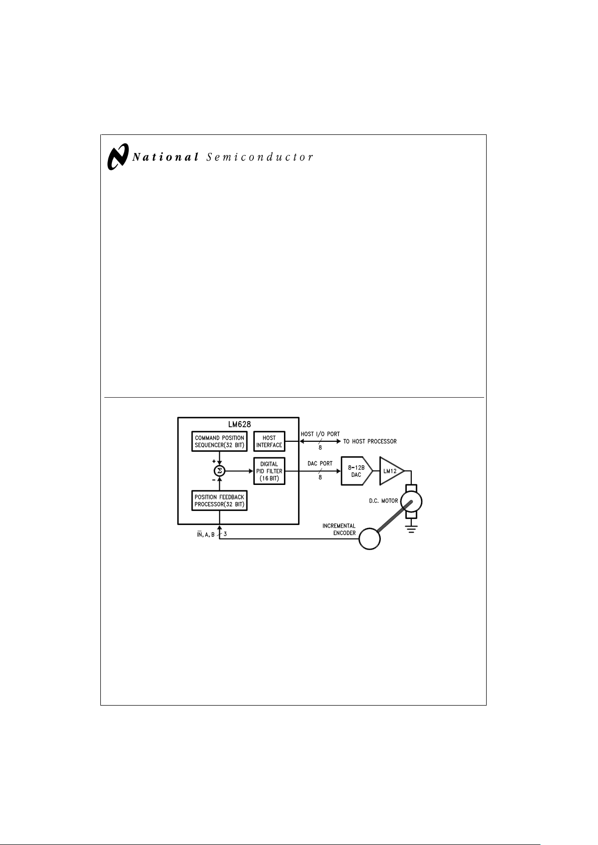
DS009219-1
FIGURE 1. Block Diagram
November 1999
LM628/LM629 Precision Motion Controller
© 1999 National Semiconductor Corporation DS009219 www.national.com
Page 2
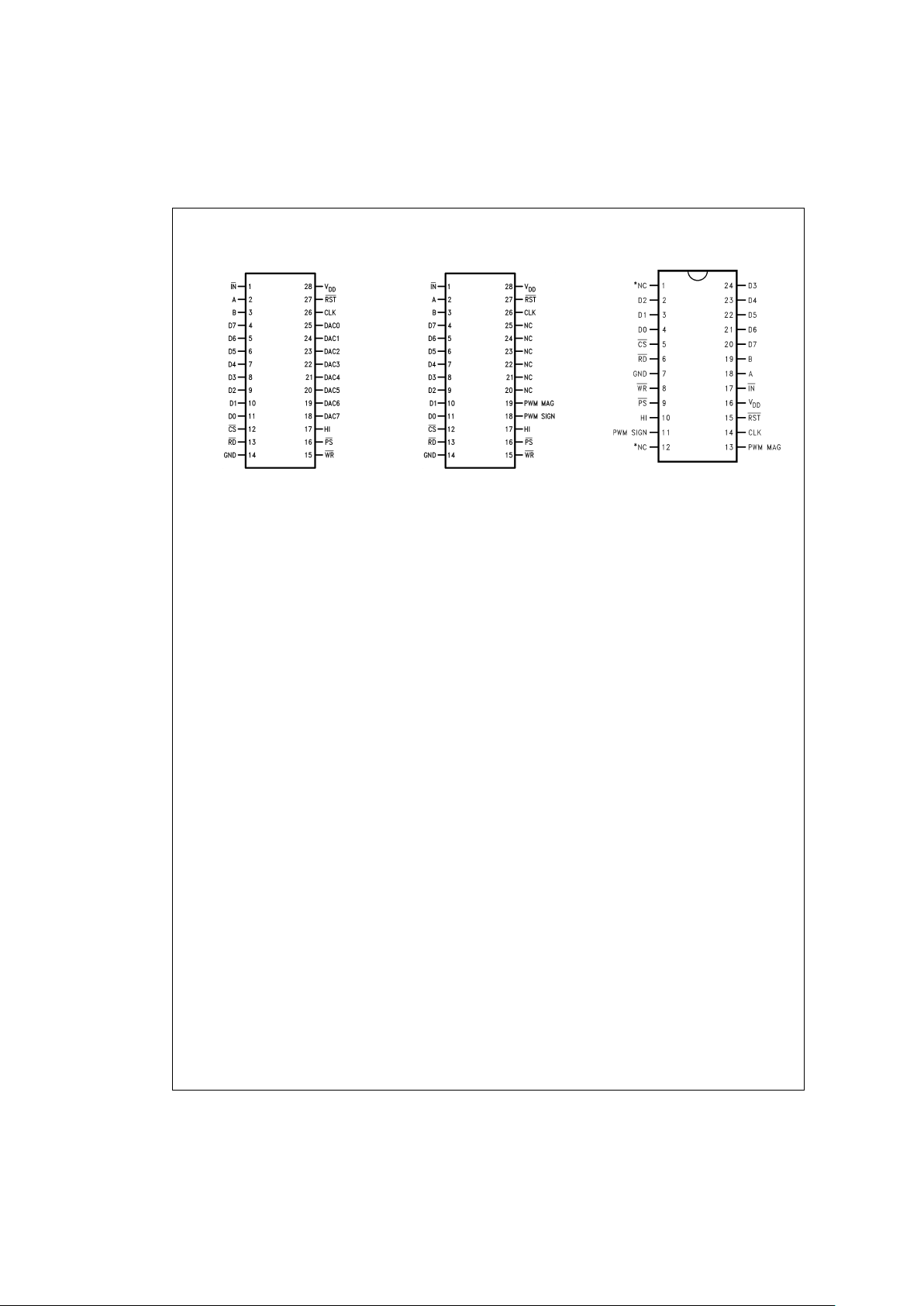
Connection Diagrams
LM628N
DS009219-2
LM629N
DS009219-3
LM629M
DS009219-21
*Do not connect.
Order Number LM629M-6, LM629M-8, LM628N-6, LM628N-8, LM629N-6 or LM629N-8
See NS Package Number M24B or N28B
LM628/LM629
www.national.com 2
Page 3
Absolute Maximum Ratings (Note 1)
If Military/Aerospace specified devices are required,
please contact the National Semiconductor Sales Office/
Distributors for availability and specifications.
Voltage at Any Pin with
Respect to GND −0.3V to +7.0V
Ambient Storage Temperature −65˚C to +150˚C
Lead Temperature
28-pin Dual In-Line
Package (Soldering, 4 sec.) 260˚C
24-pin Surface Mount
Package (Soldering, 10 sec.) 300˚C
Maximum Power Dissipation
(T
A
≤ 85˚C, (Note 2) 605 mW
ESD Tolerance
(C
ZAP
=
120 pF, R
ZAP
=
1.5k) 2000V
Operating Ratings
Temperature Range −40˚C<T
A
<
+85˚C
Clock Frequency:
LM628N-6, LM629N-6,
LM629M-6 1.0 MHz
<
f
CLK
<
6.0 MHz
LM628N-8, LM629N-8,
LM629M-8 1.0 MHz
<
f
CLK
<
8.0 MHz
V
DD
Range 4.5V<V
DD
<
5.5V
DC Electrical Characteristics
(VDDand TAper Operating Ratings; f
CLK
=
6 MHz)
Symbol Parameter Conditions Tested Limits Units
Min Max
I
DD
Supply Current Outputs Open 110 mA
INPUT VOLTAGES
V
IH
Logic 1 Input Voltage 2.0 V
V
IL
Logic 0 Input Voltage 0.8 V
I
IN
Input Currents 0 ≤ VIN≤ V
DD
−10 10 µA
OUTPUT VOLTAGES
V
OH
Logic 1 I
OH
=
−1.6 mA 2.4 V
V
OL
Logic 0 I
OL
=
1.6 mA 0.4 V
I
OUT
TRI-STATE®Output Leakage Current 0 ≤ V
OUT
≤ V
DD
−10 10 µA
AC Electrical Characteristics
(VDDand TAper Operating Ratings; f
CLK
=
6 MHz; C
LOAD
=
50 pF; Input Test Signal t
r
=
t
f
=
10 ns)
Timing Interval T
#
Tested Limits Units
Min Max
ENCODER AND INDEX TIMING (See
Figure 2
)
Motor-Phase Pulse Width T1
µs
Dwell-Time per State T2
µs
Index Pulse Setup and Hold T3 0 µs
(Relative to A and B Low)
CLOCK AND RESET TIMING (See
Figure 3
)
Clock Pulse Width
LM628N-6, LM629N-6, LM629M-6 T4 78 ns
LM628N-8, LM629N-8, LM629M-8 T4 57 ns
Clock Period
LM628N-6, LM629N-6, LM629M-6 T5 166 ns
LM628N-8, LM629N-8, LM629M-8 T5 125 ns
Reset Pulse Width T6
µs
LM628/LM629
www.national.com3
Page 4

AC Electrical Characteristics (Continued)
(VDDand TAper Operating Ratings; f
CLK
=
6 MHz; C
LOAD
=
50 pF; Input Test Signal t
r
=
t
f
=
10 ns)
Timing Interval T
#
Tested Limits Units
Min Max
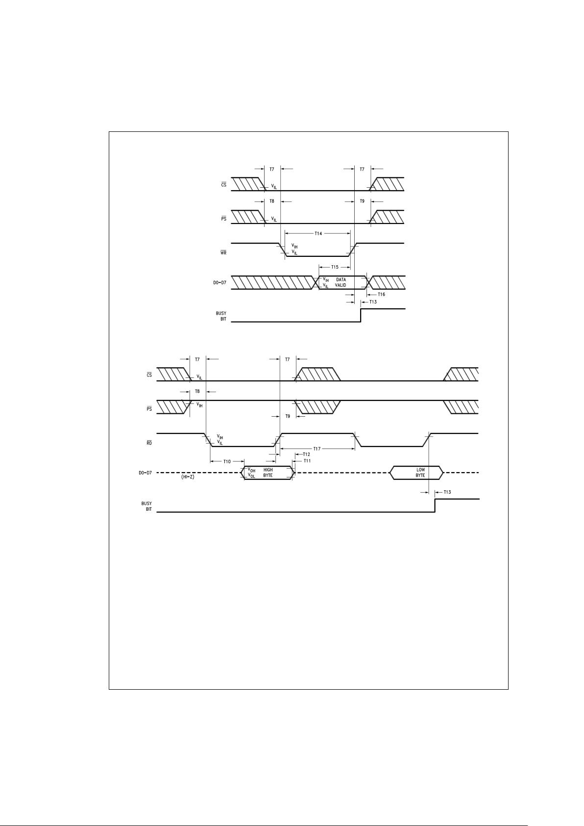
STATUS BYTE READ TIMING (See
Figure 4
)
Chip-Select Setup/Hold Time T7 0 ns
Port-Select Setup Time T8 30 ns
Port-Select Hold Time T9 30 ns
Read Data Access Time T10 180 ns
Read Data Hold Time T11 0 ns
RD High to Hi-Z Time
T12 180 ns
COMMAND BYTE WRITE TIMING (See
Figure 5
)
Chip-Select Setup/Hold Time T7 0 ns
Port-Select Setup Time T8 30 ns
Port-Select Hold Time T9 30 ns
Busy Bit Delay T13 (Note 3) ns
WR Pulse Width
T14 100 ns
Write Data Setup Time T15 50 ns
Write Data Hold Time T16 120 ns
DATA WORD READ TIMING (See
Figure 6
)
Chip-Select Setup/Hold Time T7 0 ns
Port-Select Setup Time T8 30 ns
Port-Select Hold Time T9 30 ns
Read Data Access Time T10 180 ns
Read Data Hold Time T11 0 ns
RD High to Hi-Z Time
T12 180 ns
Busy Bit Delay T13 (Note 3) ns
Read Recovery Time T17 120 ns
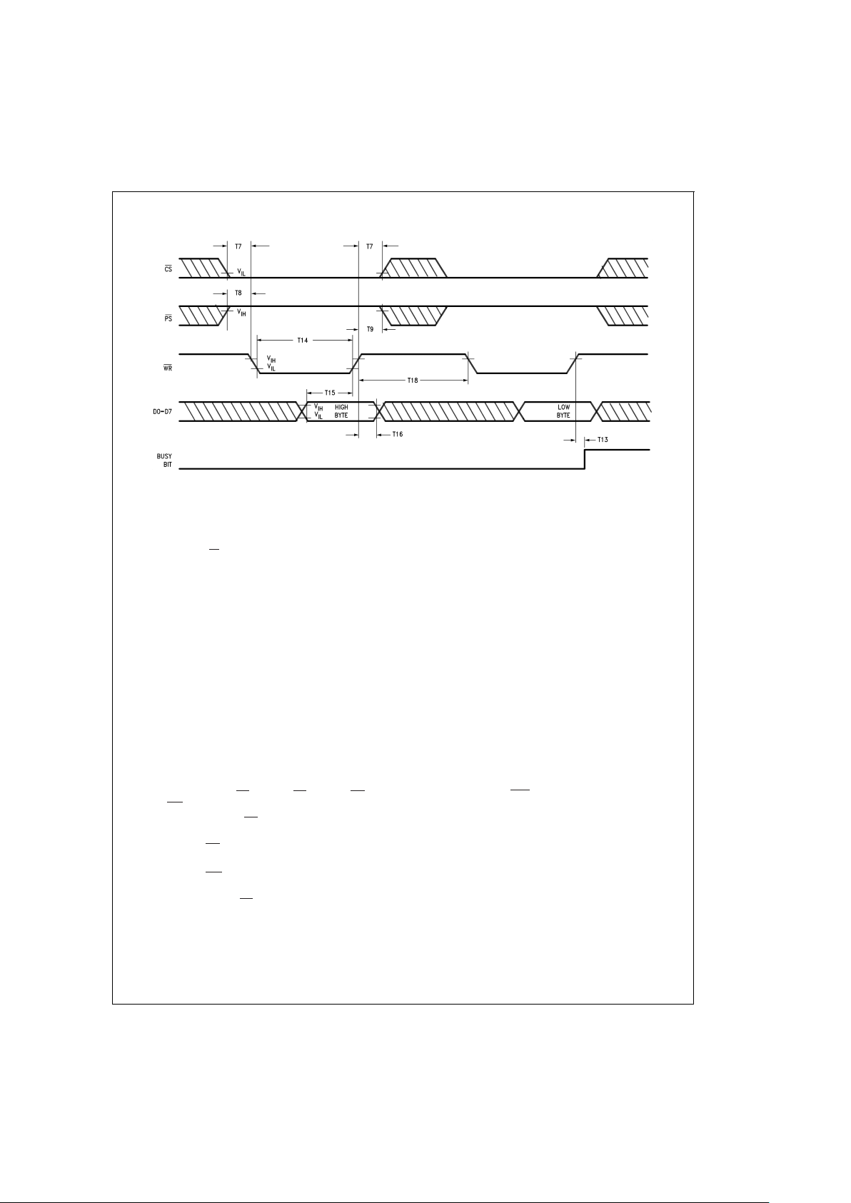
DATA WORD WRITE TIMING (See
Figure 7
)
Chip-Select Setup/Hold Time T7 0 ns
Port-Select Setup Time T8 30 ns
Port-Select Hold Time T9 30 ns
Busy Bit Delay T13 (Note 3) ns
WR Pulse Width
T14 100 ns
Write Data Setup Time T15 50 ns
Write Data Hold Time T16 120 ns
Write Recovery Time T18 120 ns
Note 1: Absolute Maximum Ratings indicate limits beyond which damage to the device may occur. DC and AC electrical specifications do not apply when operating
the device beyond the above Operating Ratings.
Note 2: When operating at ambient temperatures above 70˚C, the device must be protected against excessive junction temperatures. Mounting the package on a
printed circuit board having an area greater than three square inches and surrounding the leads and body with wide copper traces and large, uninterrupted areas of
copper, such as a ground plane, suffices. The 28-pin DIP (N) and the 24-pin surface mount package (M) are molded plastic packages with solid copper lead frames.
Most of the heat generated at the die flows from the die, through the copper lead frame, and into copper traces on the printed circuit board. The copper traces act
as a heat sink. Double-sided or multi-layer boards provide heat transfer characteristics superior to those of single-sided boards.
Note 3: In order to read the busy bit, the status byte must first be read. The time required to read the busy bit far exceeds the time the chip requires to set the busy
bit. It is, therefore, impossible to test actual busy bit delay. The busy bit is guaranteed to be valid as soon as the user is able to read it.
LM628/LM629
www.national.com 4
Page 5
AC Electrical Characteristics (Continued)
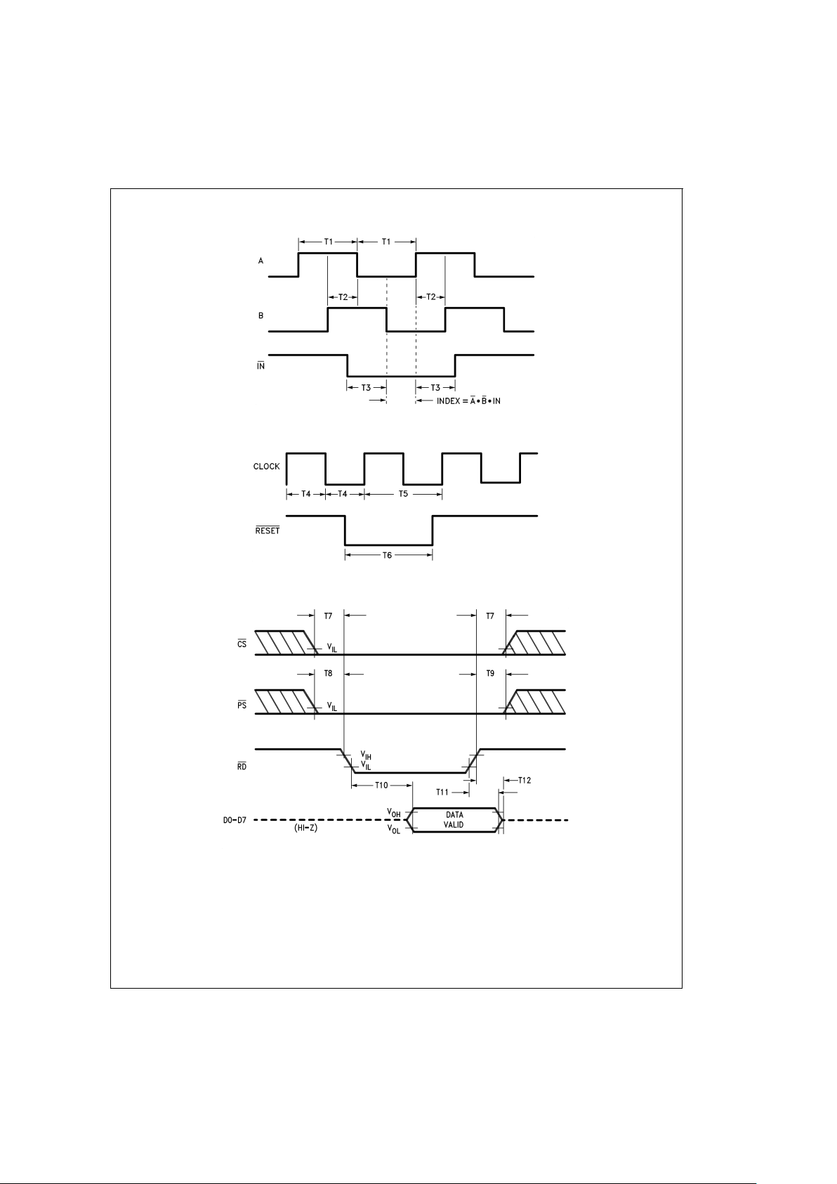
DS009219-4
FIGURE 2. Quadrature Encoder Input Timing
DS009219-5
FIGURE 3. Clock and Reset Timing
DS009219-6
FIGURE 4. Status Byte Read Timing
LM628/LM629
www.national.com5
Page 6
AC Electrical Characteristics (Continued)
DS009219-7
FIGURE 5. Command Byte Write Timing
DS009219-8
FIGURE 6. Data Word Read Timing
LM628/LM629
www.national.com 6
Page 7
AC Electrical Characteristics (Continued)
Pinout Description
(See Connection Diagrams) Pin numbers for the 24-pin surface mount package are indicated in parentheses.
Pin 1 (17), Index (IN) Input: Receives optional index pulse
from the encoder. Must be tied high if not used. The index
position is read when Pins 1, 2, and 3 are low.
Pins 2 and 3 (18 and 19), Encoder Signal (A, B) Inputs:
Receive the two-phase quadrature signals provided by the
incremental encoder. When the motor is rotating in the positive (“forward”) direction, the signal at Pin 2 leads the signal
at Pin 3 by 90 degrees. Note that the signals at Pins 2 and 3
must remain at each encoder state (See
Figure 9
) for a minimum of 8 clock periods in order to be recognized. Because
of a four-to-one resolution advantage gained by the method
of decoding the quadrature encoder signals, this corresponds to a maximum encoder-state capture rate of 1.0 MHz
(f
CLK
=
8.0 MHz) or 750 kHz (f
CLK
=
6.0 MHz). For other
clock frequencies the encoder signals must also remain at
each state a minimum of 8 clock periods.
Pins 4 to 11 (20 to 24 and 2 to 4), Host I/O Port (D0 to D7):
Bi-directional data port which connects to host computer/
processor. Used for writing commands and data to the
LM628, and for reading the status byte and data from the
LM628, as controlled by CS (Pin 12), PS (Pin 16), RD (Pin
13), and WR (Pin 15).
Pin 12 (5), Chip Select (CS ) Input: Used to select the
LM628 for writing and reading operations.
Pin 13 (6), Read (RD ) Input: Used to read status and data.
Pin 14 (7), Ground (GND): Power-supply return pin.
Pin 15 (8), Write (WR ) Input: Used to write commands and
data.
Pin 16 (9), Port Select (PS ) Input: Used to select com-
mand or data port. Selects command port when low, data
port when high. The following modes are controlled by Pin
16:
1. Commands are written to the command port (Pin 16
low),
2. Status byte is read from command port (Pin 16 low), and
3. Data is written and read via the data port (Pin 16 high).
Pin 17 (10), Host Interrupt (HI) Output: This active-high
signal alerts the host (via a host interrupt service routine)
that an interrupt condition has occurred.
Pins 18 to 25, DAC Port (DAC0 to DAC7): Output port
which is used in three different modes:
1. LM628 (8-bit output mode): Outputs latched data to the
DAC. The MSB is Pin 18 and the LSB is Pin 25.
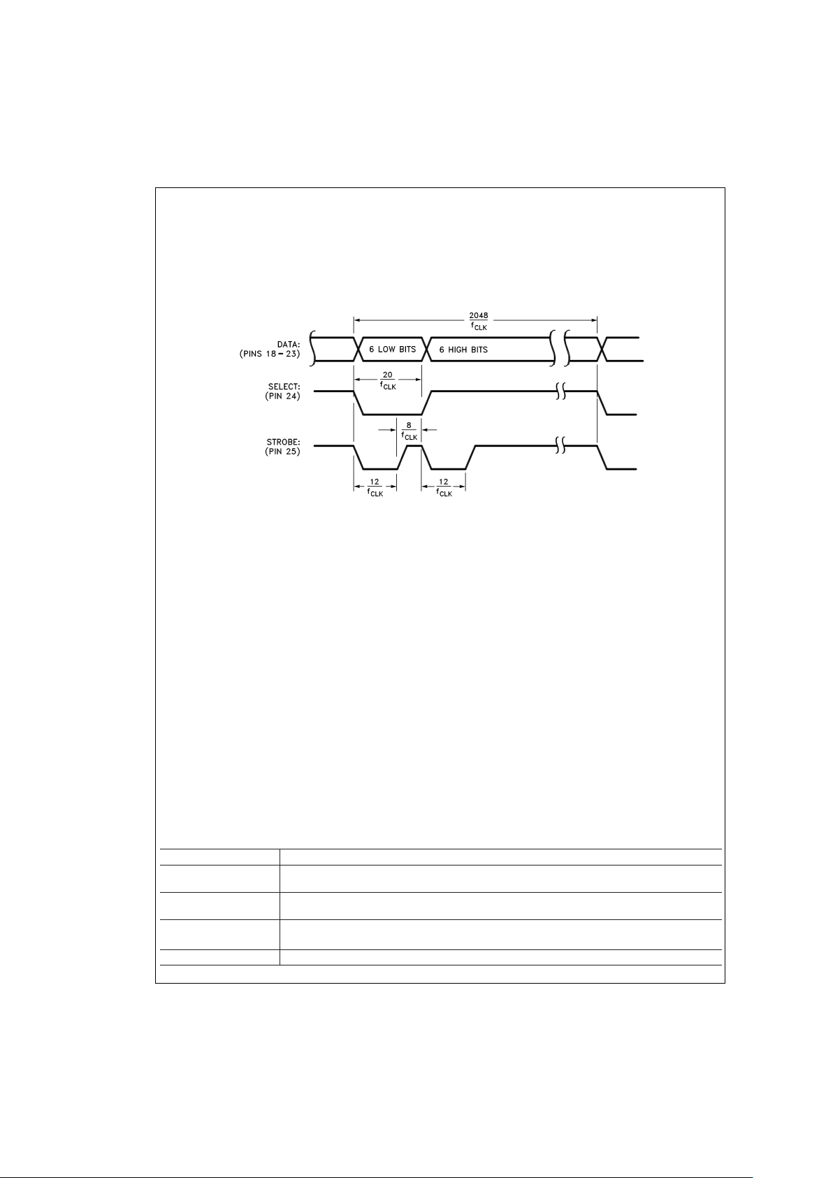
2. LM628 (12-bit output mode): Outputs two, multiplexed
6-bit words. The less-significant word is output first. The
MSB is on Pin 18 and the LSB is on Pin 23. Pin 24 is
used to demultiplex the words; Pin 24 is low for the
less-significant word. The positive-going edge of the signal on Pin 25 is used to strobe the output data.
Figure 8
shows the timing of the multiplexed signals.
3. LM629 (sign/magnitude outputs): Outputs a PWM sign
signal on Pin 18 (11 for surface mount), and a PWM
magnitude signal on Pin 19 (13 for surface mount). Pins
20 to 25 are not used in the LM629.
Figure 11
shows the
PWM output signal format.
Pin 26 (14), Clock (CLK) Input: Receives system clock.
Pin 27 (15), Reset (RST) Input: Active-low, positive-edge
triggered, resets the LM628 to the internal conditions shown
below. Note that the reset pulse must be logic low for a minimum of 8 clock periods. Reset does the following:
1. Filter coefficient and trajectory parameters are zeroed.
2. Sets position error threshold to maximum value (7FFF
hex), and effectively executes command LPEI.
3. The SBPA/SBPR interrupt is masked (disabled).
4. The five other interrupts are unmasked (enabled).
5. Initializes current position to zero, or “home” position.
6. Sets derivative sampling interval to 2048/f
CLK
or 256 µs
for an 8.0 MHz clock.
7. DAC port outputs 800 hex to “zero” a 12-bit DAC and
then reverts to 80 hex to “zero” an 8-bit DAC.
DS009219-9
FIGURE 7. Data Word Write Timing
LM628/LM629
www.national.com7
Page 8
Pinout Description (Continued)
Immediately after releasing the reset pin from the LM628,
the status port should read “00”. If the reset is successfully
completed, the status word will change to hex “84” or “C4”
within 1.5 ms. If the status word has not changed from hex
“00” to “84” or “C4” within 1.5 ms, perform another reset and
repeat the above steps. To be certain that the reset was
properly performed, execute a RSTI command. If the chip
has reset properly, the status byte will change from hex “84”
or “C4” to hex “80” or “C0”. If this does not occur, perform another reset and repeat the above steps.
Pin 28 (16), Supply Voltage (V
DD
): Power supply voltage
(+5V).
Theory of Operation
INTRODUCTION
The typical system block diagram (See
Figure 1
) illustrates a
servo system built using the LM628. The host processor
communicates with the LM628 through an I/O port to facilitate programming a trapezoidal velocity profile and a digital
compensation filter. The DAC output interfaces to an external digital-to-analog converter to produce the signal that is
power amplified and applied to the motor.An incremental encoder provides feedback for closing the position servo loop.
The trapezoidal velocity profile generator calculates the required trajectory for either position or velocity mode of operation. In operation, the LM628 subtracts the actual position
(feedback position) from the desired position (profile generator position), and the resulting position error is processed by
the digital filter to drive the motor to the desired position.
Table1
provides a brief summary of specifications offered by
the LM628/LM629:
POSITION FEEDBACK INTERFACE
The LM628 interfaces to a motor via an incremental encoder.
Three inputs are provided: two quadrature signal inputs, and
an index pulse input. The quadrature signals are used to
keep track of the absolute position of the motor. Each time a
logic transition occurs at one of the quadrature inputs, the
LM628 internal position register is incremented or decremented accordingly. This provides four times the resolution
over the number of lines provided by the encoder. See
Fig-
ure 9
. Each of the encoder signal inputs is synchronized with
the LM628 clock.
The optional index pulse output provided by some encoders
assumes the logic-low state once per revolution. If the
LM628 is so programmed by the user, it will record the absolute motor position in a dedicated register (the index register)
at the time when all three encoder inputs are logic low.
If the encoder does not provide an index output, the LM628
index input can also be used to record the home position of
the motor. In this case, typically,the motor will close a switch
which is arranged to cause a logic-low level at the index input, and the LM628 will record motor position in the index
register and alert (interrupt) the host processor. Permanently
grounding the index input will cause the LM628 to malfunction.
TABLE 1. System Specifications Summary
Position Range −1,073,741,824 to 1,073,741,823 counts
Velocity Range 0 to 1,073,741,823/2
16
counts/sample; ie, 0 to 16,383 counts/sample, with a resolution of 1/2
16
counts/sample
Acceleration Range 0 to 1,073,741,823/2
16
counts/sample/sample; ie, 0 to 16,383 counts/sample/sample, with a
resolution of 1/2
16
counts/sample/sample
Motor Drive Output LM628: 8-bit parallel output to DAC, or 12-bit multiplexed output to DAC
LM629: 8-bit PWM sign/magnitude signals
Operating Modes Position and Velocity
DS009219-10
FIGURE 8. 12-Bit Multiplexed Output Timing
LM628/LM629
www.national.com 8
Page 9

Theory of Operation (Continued)
TABLE 1. System Specifications Summary (Continued)
Feedback Device Incremental Encoder (quadrature signals; support for index pulse)
Control Algorithm Proportional Integral Derivative (PID) (plus programmable integration limit)
Sample Intervals Derivative Term: Programmable from 2048/f
CLK
to (2048*256)/f
CLK
in steps of 2048/f
CLK
(256
to 65,536 µs for an 8.0 MHz clock).
Proportional and Integral: 2048/f
CLK
VELOCITY PROFILE (TRAJECTORY) GENERATION
The trapezoidal velocity profile generator computes the desired position of the motor versus time. In the position mode
of operation, the host processor specifies acceleration, maximum velocity, and final position. The LM628 uses this information to affect the move by accelerating as specified until
the maximum velocity is reached or until deceleration must
begin to stop at the specified final position. The deceleration
rate is equal to the acceleration rate. At any time during the
move the maximum velocity and/or the target position may
be changed, and the motor will accelerate or decelerate accordingly.
Figure 10
illustrates two typical trapezoidal veloc-
ity profiles.
Figure 10
(a) shows a simple trapezoid, while
Fig-
ure 10
(b) is an example of what the trajectory looks like
when velocity and position are changed at different times
during the move.
When operating in the velocity mode, the motor accelerates
to the specified velocity at the specified acceleration rate and
maintains the specified velocity until commanded to stop.
The velocity is maintained by advancing the desired position
at a constant rate. If there are disturbances to the motion
during velocity mode operation, the long-time average velocity remains constant. If the motor is unable to maintain the
specified velocity (which could be caused by a locked rotor,
for example), the desired position will continue to be increased, resulting in a very large position error. If this condi-
DS009219-11
FIGURE 9. Quadrature Encoder Signals
DS009219-12
FIGURE 10. Typical Velocity Profiles
LM628/LM629
www.national.com9
Page 10

Theory of Operation (Continued)
tion goes undetected, and the impeding force on the motor is
subsequently released, the motor could reach a very high
velocity in order to catch up to the desired position (which is
still advancing as specified). This condition is easily detected; see commands LPEI and LPES.
All trajectory parameters are 32-bit values. Position is a
signed quantity. Acceleration and velocity are specified as
16-bit, positive-only integers having 16-bit fractions. The integer portion of velocity specifies how many counts per sampling interval the motor will traverse. The fractional portion
designates an additional fractional count per sampling interval. Although the position resolution of the LM628 is limited
to integer counts, the fractional counts provide increased average velocity resolution. Acceleration is treated in the same
manner. Each sampling interval the commanded acceleration value is added to the current desired velocity to generate
a new desired velocity (unless the command velocity has
been reached).
One determines the trajectory parameters for a desired
move as follows. If, for example, one has a 500-line shaft encoder,desires that the motor accelerate at one revolution per
second per second until it is moving at 600 rpm, and then decelerate to a stop at a position exactly 100 revolutions from
the start, one would calculate the trajectory parameters as
follows:
let P=target position (units=encoder counts)
let R=encoder lines
*
4 (system resolution)
then R=500
*
4=2000
and P=2000
*
desired number of revolutions
P=2000
*
100 revs=200,000 counts (value to load)
P (coding)=00030D40 (hex code written to LM628)
let V=velocity (units=counts/sample)
let T=sample time (seconds)=341 µs (with 6 MHz
clock)
let C=conversion factor=1 minute/60 seconds
then V=R
*T*C*
desired rpm
and V=2000
*
341E−6*1/60*600 rpm
V=6.82 counts/sample
V (scaled)=6.82
*
65,536=446,955.52
V (rounded)=446,956 (value to load)
V (coding)=0006D1EC (hex code written to LM628)
let A=acceleration (units=counts/sample/sample)
A=R
*T*T*
desired acceleration (rev/sec/sec)
then A=2000
*
341E−6*341E-6*1 rev/sec/sec
and A=2.33E−4 counts/sample/sample
A (scaled)=2.33E−4
*
65,536=15.24
A (rounded)=15 (value to load)
A (coding)=0000000F (hex code written to LM628)
The above position, velocity, and acceleration values must
be converted to binary codes to be loaded into the LM628.
The values shown for velocity and acceleration must be multiplied by 65,536 (as shown) to adjust for the required
integer/fraction format of the input data. Note that after scaling the velocity and acceleration values, literal fractional data
cannot be loaded; the data must be rounded and converted
to binary. The factor of four increase in system resolution is
due to the method used to decode the quadrature encoder
signals, see
Figure 9
.
PID COMPENSATION FILTER
The LM628 uses a digital Proportional Integral Derivative
(PID) filter to compensate the control loop. The motor is held
at the desired position by applying a restoring force to the
motor that is proportional to the position error, plus the integral of the error, plus the derivative of the error.The following
discrete-time equation illustrates the control performed by
the LM628:
(1)
where u(n) is the motor control signal output at sample time
n, e(n) is the position error at sample time n, n' indicates sampling at the derivative sampling rate, and
kp, ki, and kd are the discrete-time filter parameters
loaded by the users.
The first term, the proportional term, provides a restoring
force porportional to the position error, just as does a spring
obeying Hooke’s law. The second term, the integration term,
provides a restoring force that grows with time, and thus ensures that the static position error is zero. If there is a constant torque loading, the motor will still be able to achieve
zero position error.
The third term, the derivative term, provides a force proportional to the rate of change of position error. It acts just like
viscous damping in a damped spring and mass system (like
a shock absorber in an automobile). The sampling interval
associated with the derivative term is user-selectable; this
capability enables the LM628 to control a wider range of inertial loads (system mechanical time constants) by providing
a better approximation of the continuous derivative. In general, longer sampling intervals are useful for low-velocity operations.
In operation, the filter algorithm receives a 16-bit error signal
from the loop summing-junction. The error signal is saturated
at 16 bits to ensure predictable behavior. In addition to being
multiplied by filter coefficient kp, the error signal is added to
an accumulation of previous errors (to form the integral signal) and, at a rate determined by the chosen
derivative
sampling interval, the previous error is subtracted from it (to form
the derivative signal). All filter multiplications are 16-bit operations; only the bottom 16 bits of the product are used.
The integral signal is maintained to 24 bits, but only the top
16 bits are used. This scaling technique results in a more usable (less sensitive) range of coefficient ki values. The 16
bits are right-shifted eight positions and multiplied by filter
coefficient ki to form the term which contributes to the motor
control output. The absolute magnitude of this product is
compared to coefficient il, and the lesser, appropriately
signed magnitude then contributes to the motor control signal.
The derivative signal is multiplied by coefficient kd each
de-
rivative
sampling interval. This product contributes to the mo-
tor control output
every
sample interval, independent of the
user-chosen
derivative
sampling interval.
The kp, limited ki, and kd product terms are summed to form
a 16-bit quantity.Depending on the output mode (wordsize),
either the top 8 or top 12 bits become the motor control output signal.
LM628/LM629
www.national.com 10
Page 11

Theory of Operation (Continued)
LM628 READING AND WRITING OPERATIONS
The host processor writes commands to the LM628 via the
host I/O port when Port Select (PS ) input (Pin 16) is logic
low. The desired command code is applied to the parallel
port line and the Write (WR ) input (Pin 15) is strobed. The
command byte is latched into the LM628 on the rising edge
of the WR input. When writing command bytes it is necessary to first read the status byte and check the state of a flag
called the “busy bit” (Bit 0). If the busy bit is logic high, no
command write may take place. The busy bit is never high
longer than 100 µs, and typically falls within 15 µs to 25 µs.
The host processor reads the LM628 status byte in a similar
manner: by strobing the Read (RD ) input (Pin 13) when PS
(Pin 16) is low; status information remains valid as long as
RD is low.
Writing and reading data to/from the LM628 (as opposed to
writing commands and reading status) are done with PS (Pin
16) logic high. These writes and reads are always an integral
number (from one to seven) of two-byte words, with the first
byte of each word being the more significant. Each byte requires a write (WR ) or read (RD ) strobe. When transferring
data words (byte-pairs), it is necessary to first read the status
byte and check the state of the busy bit. When the busy bit is
logic low, the user may then sequentially transfer both bytes
comprising a data word, but the busy bit must again be
checked and found to be low before attempting to transfer
the next byte pair (when transferring multiple words). Data
transfers are accomplished via LM628-internal interrupts
(which are not nested); the busy bit informs the host processor when the LM628 may not be interrupted for data transfer
(or a command byte). If a command is written when the busy
bit is high, the command will be ignored.
The busy bit goes high immediately after writing a command
byte, or reading or writing a second byte of data (See
Figure
5
thru
Figure 7
).
MOTOR OUTPUTS
The LM628 DAC output port can be configured to provide either a latched eight-bit parallel output or a multiplexed 12-bit
output. The 8-bit output can be directly connected to a
flow-through (non-input-latching) D/A converter; the 12-bit
output can be easily demultiplexed using an external 6-bit
latch and an input-latching 12-bit D/A converter. The DAC
output data is offset-binary coded; the 8-bit code for zero is
80 hex and the 12-bit code for zero is 800 hex. Values less
than these cause a negative torque to be applied to the motor and, conversely, larger values cause positive motor
torque. The LM628, when configured for 12-bit output, provides signals which control the demultiplexing process. See
for details.
The LM629 provides 8-bit, sign and magnitude PWM output
signals for directly driving switch-mode motor-drive amplifiers.
Figure 11
shows the format of the PWM magnitude out-
put signal.
TABLE 2. LM628 User Command Set
Command Type Description Hex Data Note
Bytes
RESET Initialize Reset LM628 00 0 1
PORT8 Initialize Select 8-Bit Output 05 0 2
PORT12 Initialize Select 12-Bit Output 06 0 2
DFH Initialize Define Home 02 0 1
SIP Interrupt Set Index Position 03 0 1
LPEI Interrupt Interrupt on Error 1B 2 1
LPES Interrupt Stop on Error 1A 2 1
SBPA Interrupt Set Breakpoint, Absolute 20 4 1
SBPR Interrupt Set Breakpoint, Relative 21 4 1
DS009219-13
FIGURE 11. PWM Output Signal Format (Sign output (pin 18) not shown)
LM628/LM629
www.national.com11
Page 12

Theory of Operation (Continued)
TABLE 2. LM628 User Command Set (Continued)
Command Type Description Hex Data Note
Bytes
MSKI Interrupt Mask Interrupts 1C 2 1
RSTI Interrupt Reset Interrupts 1D 2 1
LFIL Filter Load Filter Parameters 1E 2 to 10 1
UDF Filter Update Filter 04 0 1
LTRJ Trajectory Load Trajectory 1F 2 to 14 1
STT Trajectory Start Motion 01 0 3
RDSTAT Report Read Status Byte None 1 1, 4
RDSIGS Report Read Signals Register 0C 2 1
RDIP Report Read Index Position 09 4 1
RDDP Report Read Desired Position 08 4 1
RDRP Report Read Real Position 0A 4 1
RDDV Report Read Desired Velocity 07 4 1
RDRV Report Read Real Velocity 0B 2 1
RDSUM Report Read Integration Sum 0D 2 1
Note 4: Commands may be executed “On the Fly” during motion.
Note 5: Commands not applicable to execution during motion.
Note 6: Command may be executed during motion if acceleration parameter was not changed.
Note 7: Command needs no code because the command port status-byte read is totally supported by hardware.
User Command Set
GENERAL
The following paragraphs describe the user command set of
the LM628. Some of the commands can be issued alone and
some require a supporting data structure. As examples, the
command STT (STarT motion) does not require additional
data; command LFIL (Load FILter parameters) requires additional data (derivative-term sampling interval and/or filter
parameters).
Commands are categorized by function: initialization, interrupt control, filter control, trajectory control, and data reporting. The commands are listed in
Table2
and described in the
following paragraphs. Along with each command name is its
command-byte code, the number of accompanying data
bytes that are to be written (or read), and a comment as to
whether the command is executable during motion.
Initialization Commands
The following four LM628 user commands are used primarily
to initialize the system for use.
RESET COMMAND: RESET the LM628
Command Code: 00 Hex
Data Bytes: None
Executable During Motion: Yes
This command (and the hardware reset input, Pin 27) results
in setting the following data items to zero: filter coefficients
and their input buffers, trajectory parameters and their input
buffers, and the motor control output. A zero motor control
output is a half-scale, offset-binary code: (80 hex for the 8-bit
output mode; 800 hex for 12-bit mode). During reset, the
DAC port outputs 800 hex to “zero” a 12-bit DAC and reverts
to 80 hex to “zero” an 8-bit DAC. The command also clears
five of the six interrupt masks (only the SBPA/SBPR interrupt
is masked), sets the output port size to 8 bits, and defines
the current absolute position as home. Reset, which may be
executed at any time, will be completed in less than 1.5 ms.
Also see commands PORT8 and PORT12.
PORT8 COMMAND: Set Output PORT Size to 8 Bits
Command Code: 05 Hex
Data Bytes: None
Executable During Motion: Not Applicable
The default output port size of the LM628 is 8 bits; so the
PORT8 command need not be executed when using an 8-bit
DAC. This command must not be executed when using a
12-bit converter; it will result in erratic, unpredictable motor
behavior. The 8-bit output port size is the required selection
when using the LM629, the PWM-output version of the
LM628.
PORT12 COMMAND: Set Output PORT Size to 12 Bits
Command Code: 06 Hex
Data Bytes: None
Executable During Motion: Not Applicable
When a 12-bit DAC is used, command PORT12 should be
issued very early in the initialization process. Because use of
this command is determined by system hardware, there is
only one foreseen reason to execute it later: if the RESET
command is issued (because an 8-bit output would then be
selected as the default) command PORT12 should be immediately executed. This command must not be issued when
using an 8-bit converter or the LM629, the PWM-output version of the LM628.
DFH COMMAND: DeFine Home
Command Code: 02 Hex
Data Bytes: None
Executable During Motion: Yes
LM628/LM629
www.national.com 12
Page 13

Initialization Commands (Continued)
This command declares the current position as “home”, or
absolute position 0 (Zero). If DFH is executed during motion
it will not affect the stopping position of the on-going move
unless command STT is also executed.
Interrupt Control Commands
The following seven LM628 user commands are associated
with conditions which can be used to interrupt the host computer. In order for any of the potential interrupt conditions to
actually interrupt the host via Pin 17, the corresponding bit in
the interrupt mask data associated with command MSKI
must have been set to logic high (the non-masked state).
The identity of all interrupts is made known to the host via
reading and parsing the status byte. Even if all interrupts are
masked off via command MSKI, the state of each condition
is still reflected in the status byte. This feature facilitates polling the LM628 for status information, as opposed to interrupt
driven operation.
SIP COMMAND: Set Index Position
Command Code: 03 Hex
Data Bytes: None
Executable During Motion: Yes
After this command is executed, the absolute position which
corresponds to the occurrence of the next index pulse input
will be recorded in the index register, and bit 3 of the status
byte will be set to logic high. The position is recorded when
both encoder-phase inputs and the index pulse input are
logic low. This register can then be read by the user (see description for command RDIP) to facilitate aligning the definition of home position (see description of command DFH)
with an index pulse. The user can also arrange to have the
LM628 interrupt the host to signify that an index pulse has
occurred. See the descriptions for commands MSKI and
RSTI.
LPEI COMMAND: Load Position Error for Interrupt
Command Code: 1B Hex
Data Bytes: Two
Data Range: 0000 to 7FFF Hex
Executable During Motion: Yes
An excessive position error (the output of the loop summing
junction) can indicate a serious system problem; e.g., a
stalled rotor. Instruction LPEI allows the user to input a
threshold for position error detection. Error detection occurs
when the absolute magnitude of the position error exceeds
the threshold, which results in bit 5 of the status byte being
set to logic high. If it is desired to also stop (turn off) the motor upon detecting excessive position error, see command
LPES, below. The first byte of threshold data written with
command LPEI is the more significant. The user can have
the LM628 interrupt the host to signify that an excessive position error has occurred. See the descriptions for commands MSKI and RSTI.
LPES COMMAND: Load Position Error for Stopping
Command Code: 1A Hex
Data Bytes: Two
Data Range: 0000 to 7FFF Hex
Executable During Motion: Yes
Instruction LPES is essentially the same as command LPEI
above, but adds the feature of turning off the motor upon detecting excessive position error. The motor drive is not actually switched off, it is set to half-scale, the offset-binary code
for zero. As with command LPEI, bit 5 of the status byte is
also set to logic high. The first byte of threshold data written
with command LPES is the more significant. The user can
have the LM628 interrupt the host to signify that an excessive position error has occurred. See the descriptions for
commands MSKI and RSTI.
SBPA COMMAND:
Command Code: 20 Hex
Data Bytes: Four
Data Range: C0000000 to 3FFFFFFF Hex
Executable During Motion: Yes
This command enables the user to set a breakpoint in terms
of absolute position. Bit 6 of the status byte is set to logic
high when the breakpoint position is reached. This condition
is useful for signaling trajectory and/or filter parameter updates. The user can also arrange to have the LM628 interrupt the host to signify that a breakpoint position has been
reached. See the descriptions for commands MSKI and
RSTI.
SBPR COMMAND:
Command Code: 21 Hex
Data Bytes: Four
Data Range: See Text
Executable During Motion: Yes
This command enables the user to set a breakpoint in terms
of relative position. As with command SBPA, bit 6 of the status byte is set to logic high when the breakpoint position
(relative to the current commanded target position) is
reached. The relative breakpoint input value must be such
that when this value is added to the target position the result
remains within the absolute position range of the system
(C0000000 to 3FFFFFFF hex). This condition is useful for
signaling trajectory and/or filter parameter updates. The user
can also arrange to have the LM628 interrupt the host to signify that a breakpoint position has been reached. See the descriptions for commands MSKI and RSTI.
MSKI COMMAND: MaSK Interrupts
Command Code: 1C Hex
Data Bytes: Two
Data Range: See Text
Executable During Motion: Yes
The MSKI command lets the user determine which potential
interrupt condition(s) will interrupt the host. Bits 1 through 6
of the status byte are indicators of the six conditions which
are candidates for host interrupt(s). When interrupted, the
host then reads the status byte to learn which condition(s)
occurred. Note that the MSKI command is immediately followed by two data bytes. Bits 1 through 6 of the second (less
significant) byte written determine the masked/unmasked
status of each potential interrupt. Any zero(s) in this 6-bit
field will mask the corresponding interrupt(s); any one(s) enable the interrupt(s). Other bits comprising the two bytes
have no effect. The mask controls only the host interrupt process; reading the status byte will still reflect the actual conditions independent of the mask byte. See
Table 3
.
LM628/LM629
www.national.com13
Page 14

Interrupt Control Commands
(Continued)
TABLE 3. Mask and Reset Bit Allocations for Interrupts
Bit Position Function
Bits 15 thru 7 Not Used
Bit 6 Breakpoint Interrupt
Bit 5 Position-Error Interrupt
Bit 4 Wrap-Around Interrupt
Bit 3 Index-Pulse Interrupt
Bit 2 Trajectory-Complete Interrupt
Bit 1 Command-Error Interrupt
Bit 0 Not Used
RSTI COMMAND: ReSeT Interrupts
Command Code: 1D Hex
Data Bytes: Two
Data Range: See Text
Executable During Motion: Yes
When one of the potential interrupt conditions of
Table3
occurs, command RSTI is used to reset the corresponding interrupt flag bit in the status byte. The host may reset one or
all flag bits. Resetting them one at a time allows the host to
service them one at a time according to a priority programmed by the user. As in the MSKI command, bits 1
through 6 of the second (less significant) byte correspond to
the potential interrupt conditions shown in
Table 3
. Also see
description of RDSTAT command. Any zero(s) in this 6-bit
field reset the corresponding interrupt(s). The remaining bits
have no effect.
Filter Control Commands
The following two LM628 user commands are used for setting the derivative-term sampling interval, for adjusting the
filter parameters as required to tune the system, and to control the timing of these system changes.
LFIL COMMAND: Load FILter Parameters
Command Code: 1E Hex
Data Bytes: Two to Ten
Data Ranges…
Filter Control Word: See Text
Filter Coefficients: 0000to 7FFF Hex (Pos Only)
Integration Limit: 0000 to 7FFF Hex (Pos Only)
Executable During Motion: Yes
The filter parameters (coefficients) which are written to the
LM628 to control loop compensation are: kp, ki, kd, and il (integration limit). The integration limit (il) constrains the contribution of the integration term
(see Eq. 1) to values equal to or less than a user-defined
maximum value; this capability minimizes integral or reset
“wind-up” (an overshooting effect of the integral action). The
positive-only input value is compared to the absolute magni-
tude of the integration term; when the magnitude of integration term value exceeds il, the il value (with appropriate sign)
is substituted for the integration term value.
The derivative-term sampling interval is also programmable
via this command. After writing the command code, the first
two data bytes that are written specify the derivative-term
sampling interval and which of the four filter parameters is/
are to be written via any forthcoming data bytes. The first
byte written is the more significant. Thus the two data bytes
constitute a filter control word that informs the LM628 as to
the nature and number of any following data bytes. See
Table 4
.
TABLE 4. Filter Control word Bit Allocation
Bit Position Function
Bit 15 Derivative Sampling Interval Bit 7
Bit 14 Derivative Sampling Interval Bit 6
Bit 13 Derivative Sampling Interval Bit 5
Bit 12 Derivative Sampling Interval Bit 4
Bit 11 Derivative Sampling Interval Bit 3
Bit 10 Derivative Sampling Interval Bit 2
Bit 9 Derivative Sampling Interval Bit 1
Bit 8 Derivative Sampling Interval Bit 0
Bit 7 Not Used
Bit 6 Not Used
Bit 5 Not Used
Bit 4 Not Used
Bit 3 Loading kp Data
Bit 2 Loading ki Data
Bit 1 Loading kd Data
Bit 0 Loading il Data
Bits 8 through 15 select the derivative-term sampling interval. See
Table 5
. The user must locally save and restore
these bits during successive writes of the filter control word.
Bits 4 through 7 of the filter control word are not used.
Bits 0 to 3 inform the LM628 as to whether any or all of the
filter parameters are about to be written. The user may
choose to update any or all (or none) of the filter parameters.
Those chosen for updating are so indicated by logic one(s) in
the corresponding bit position(s) of the filter control word.
The data bytes specified by and immediately following the filter control word are written in pairs to comprise 16-bit words.
The order of sending the data words to the LM628 corresponds to the descending order shown in the above description of the filter control word; i.e., beginning with kp, then ki,
kd and il. The first byte of each word is the more-significant
byte. Prior to writing a word (byte pair) it is necessary to
check the busy bit in the status byte for readiness. The required data is written to the primary buffers of a
double-buffered scheme by the above described operations;
it is not transferred to the secondary (working) registers until
the UDF command is executed. This fact can be used advantageously; the user can input numerous data ahead of
their actual use. This simple pipeline effect can relieve potential host computer data communications bottlenecks, and
facilitates easier synchronization of multiple-axis controls.
UDF COMMAND: UpDate Filter
Command Code: 04 Hex
Data Bytes: None
LM628/LM629
www.national.com 14
Page 15

Filter Control Commands (Continued)
Executable During Motion: Yes
The UDF command is used to update the filter parameters,
the specifics of which have been programmed via the LFIL
command. Any or all parameters (derivative-term sampling
interval, kp, ki, kd, and/or il) may be changed by the appropriate command(s), but command UDF must be executed to
affect the change in filter tuning. Filter updating is synchronized with the calculations to eliminate erratic or spurious
behavior.
Trajectory Control Commands
The following two LM628 user commands are used for setting the trajectory control parameters (position, velocity, acceleration), mode of operation (position or velocity), and direction (velocity mode only) as required to describe a
desired motion or to select the mode of a manually directed
stop, and to control the timing of these system changes.
LTRJ COMMAND: Load TRaJectory Parameters
Command Code: 1F Hex
Data Bytes: Two to Fourteen
Data Ranges…
Trajectory Control
Word: See Text
Position: C0000000 to 3FFFFFFF Hex
Velocity: 00000000 to 3FFFFFFF Hex
(Pos Only)
Acceleration: 00000000 to 3FFFFFFF Hex
(Pos Only)
Executable During
Motion: Conditionally, See Text
TABLE 5. Derivative-Term Sampling Interval Selection Codes
Bit Position Selected Derivative
15 14 13 12 11 10 9 8 Sampling Interval
00000000256µs
00000001512µs
00000010768µs
000000111024 µs, etc…
thru 1111111165,536 µs
Note 8: Sampling intervals shown are when using an 8.0 MHz clock. The 256 corresponds to 2048/8 MHz; sample intervals must be scaled for other clock frequencies.
The trajectory control parameters which are written to the
LM628 to control motion are: acceleration, velocity, and position. In addition, indications as to whether these three parameters are to be considered as absolute or relative inputs,
selection of velocity mode and direction, and manual stopping mode selection and execution are programmable via
this command. After writing the command code, the first two
data bytes that are written specify which parameter(s) is/are
being changed. The first byte written is the more significant.
Thus the two data bytes constitute a trajectory control word
that informs the LM628 as to the nature and number of any
following data bytes. See
Table 6
.
TABLE 6. Trajectory Control Word Bit Allocation
Bit Position Function
Bit 15 Not Used
Bit 14 Not Used
Bit 13 Not Used
Bit 12 Forward Direction (Velocity Mode Only)
Bit 11 Velocity Mode
Bit 10 Stop Smoothly (Decelerate as
Programmed)
Bit 9 Stop Abruptly (Maximum Deceleration)
Bit 8 Turn Off Motor (Output Zero Drive)
Bit 7 Not Used
Bit 6 Not Used
Bit Position Function
Bit 5 Acceleration Will Be Loaded
Bit 4 Acceleration Data Is Relative
Bit 3 Velocity Will Be Loaded
Bit 2 Velocity Data Is Relative
Bit 1 Position Will Be Loaded
Bit 0 Position Data Is Relative
Bit 12 determines the motor direction when in the velocity
mode.A logic one indicates forward direction. This bit has no
effect when in position mode.
Bit 11 determines whether the LM628 operates in velocity
mode (Bit 11 logic one) or position mode (Bit 11 logic zero).
Bits 8 through 10 are used to select the method of
manually
stopping
the motor. These bits are
not
provided for one to
merely specify the desired
mode
of stopping, in position
mode operations, normal stopping is always smooth and occurs automatically at the end of the specified trajectory. Under exceptional circumstances it may be desired to manually
intervene with the trajectory generation process to affect a
premature stop. In velocity mode operations, however, the
normal means of stopping
is
via bits 8 through 10 (usually bit
10). Bit 8 is set to logic one to stop the motor by turning off
motor drive output (outputting the appropriate offset-binary
code to apply zero drive to the motor); bit 9 is set to one to
stop the motor abruptly (at maximum available acceleration,
by setting the target position equal to the current position);
and bit 10 is set to one to stop the motor smoothly by using
LM628/LM629
www.national.com15
Page 16

Trajectory Control Commands
(Continued)
the current user-programmed acceleration value. Bits 8
through 10 are to be used
exclusively;
only one bit should be
a logic one at any time.
Bits 0 through 5 inform the LM628 as to whether any or all of
the trajectory controlling parameters are about to be written,
and whether the data should be interpreted as absolute or
relative. The user may choose to update any or all (or none)
of the trajectory parameters. Those chosen for updating are
so indicated by logic one(s) in the corresponding bit position(s). Any parameter may be changed while the motor is in
motion; however, if acceleration is changed then the next
STT command must not be issued until the LM628 has completed the current move or has been manually stopped.
The data bytes specified by and immediately following the
trajectory control word are written in pairs which comprise
16-bit words. Each data item (parameter) requires two 16-bit
words; the word and byte order is most-to-least significant.
The order of sending the parameters to the LM628 corresponds to the descending order shown in the above description of the trajectory control word; i.e., beginning with acceleration, then velocity, and finally position.
Acceleration and velocity are 32 bits, positive only, but range
only from 0 (00000000 hex) to [2
30
]−1 (3FFFFFFF hex). The
bottom 16 bits of both acceleration and velocity are scaled
as fractional data; therefore, the least-significant integer data
bit for these parameters is bit 16 (where the bits are numbered 0 through 31). Todetermine the coding for a given velocity, for example, one multiplies the desired velocity (in
counts per sample interval) times 65,536 and converts the
result to binary. The units of acceleration are counts per
sample per sample. The value loaded for acceleration must
not exceed the value loaded for velocity.Position is a signed,
32-bit integer, but ranges only from −[2
30
] (C0000000 hex) to
[2
30
]−1 (3FFFFFFF Hex).
The required data is written to the primary buffers of a
double-buffered scheme by the above described operations;
it is not transferred to the secondary (working) registers until
the STT command is executed. This fact can be used advantageously; the user can input numerous data ahead of their
actual use. This simple pipeline effect can relieve potential
host computer data communications bottlenecks, and facilitates easier synchronization of multiple-axis controls.
STT COMMAND: STarT Motion Control
Command Code: 01 Hex
Data Bytes: None
Executable During Motion: Yes, if acceleration has not
been changed
The STT command is used to execute the desired trajectory,
the specifics of which have been programmed via the LTRJ
command. Synchronization of multi-axis control (to within
one sample interval) can be arranged by loading the required trajectory parameters for each (and every) axis and
then simultaneously issuing a single STT command to all
axes. This command may be executed at any time, unless
the acceleration value has been changed and a trajectory
has not been completed or the motor has not been manually
stopped. If STT is issued during motion and acceleration has
been changed, a command error interrupt will be generated
and the command will be ignored.
Data Reporting Commands
The following seven LM628 user commands are used to obtain data from various registers in the LM628. Status, position, and velocity information are reported. With the exception of RDSTAT, the data is read from the LM628 data port
after first writing the corresponding command to the command port.
RDSTAT COMMAND: ReaD STATus Byte
Command Code: None
Byte Read: One
Data Range: See Text
Executable During Motion: Yes
The RDSTATcommand is really not a command, but is listed
with the other commands because it is used very frequently
to control communications with the host computer. There is
no identification code; it is directly supported by the hardware and may be executed at any time. The single-byte status read is selected by placing CS , PS and RD at logic zero.
See
Table 7
.
TABLE 7. Status Byte Bit Allocation
Bit Position Function
Bit 7 Motor Off
Bit 6 Breakpoint Reached [Interrupt]
Bit 5 Excessive Position Error [Interrupt]
Bit 4 Wraparound Occurred [Interrupt]
Bit 3 Index Pulse Observed [Interrupt]
Bit 2 Trajectory Complete [Interrupt]
Bit 1 Command Error [Interrupt]
Bit 0 Busy Bit
Bit 7, the motor-off flag, is set to logic one when the motor
drive output is off (at the half-scale, offset-binary code for
zero). The motor is turned off by any of the following conditions: power-up reset, command RESET, excessive position
error (if command LPES had been executed), or when command LTRJ is used to manually stop the motor via turning
the motor off. Note that when bit 7 is set in conjunction with
command LTRJ for producing a manual, motor-off stop, the
actual setting of bit 7 does not occur until command STT is
issued to affect the stop. Bit 7 is cleared by command STT,
except as described in the previous sentence.
Bit 6, the breakpoint-reached interrupt flag, is set to logic one
when the position breakpoint loaded via command SBPAor
SBPR has been exceeded. The flag is functional independent of the host interrupt mask status. Bit 6 is cleared via
command RSTI.
Bit 5, the excessive-position-error interrupt flag, is set to
logic one when a position-error interrupt condition exists.
This occurs when the error threshold loaded via command
LPEI or LPES has been exceeded. The flag is functional independent of the host interrupt mask status. Bit 5 is cleared
via command RSTI.
Bit 4, the wraparound interrupt flag, is set to logic one when
a numerical “wraparound” has occurred. To “wraparound”
means to exceed the position address space of the LM628,
which could occur during velocity mode operation. If a wraparound has occurred, then position information will be in error and this interrupt helps the user to ensure position data
integrity.The flag is functional independent of the host interrupt mask status. Bit 4 is cleared via command RSTI.
LM628/LM629
www.national.com 16
Page 17

Data Reporting Commands (Continued)
Bit 3, the index-pulse acquired interrupt flag, is set to logic
one when an index pulse has occurred (if command SIP had
been executed) and indicates that the index position register
has been updated. The flag is functional independent of the
host interrupt mask status. Bit 3 is cleared by command
RSTI.
Bit 2, the trajectory complete interrupt flag, is set to logic one
when the trajectory programmed by the LTRJ command and
initiated by the STT command has been completed. Because of overshoot or a limiting condition (such as commanding the velocity to be higher than the motor can
achieve), the motor may not yet be at the final commanded
position. This bit is the logical OR of bits 7 and 10 of the Signals Register, see command RDSIGS below. The flag functions independently of the host interrupt mask status. Bit 2 is
cleared via command RSTI.
Bit 1, the command-error interrupt flag, is set to logic one
when the user attempts to read data when a write was appropriate (or vice versa). The flag is functional independent
of the host interrupt mask status. Bit 1 is cleared via command RSTI.
Bit 0, the busy flag, is frequently tested by the user (via the
host computer program) to determine the busy/ready status
prior to writing and reading any data. Such writes and reads
may be executed only when bit 0 is logic zero (not busy). Any
command or data writes when the busy bit is high will be ignored. Any data reads when the busy bit is high will read the
current contents of the I/O port buffers, not the data expected by the host. Such reads or writes (with the busy bit
high) will not generate a command-error interrupt.
RDSIGS COMMAND: ReaD SIGnalS Register
Command Code: 0C Hex
Bytes Read: Two
Data Range: See Text
Executable During Motion: Yes
The LM628 internal “signals” register may be read using this
command. The first byte read is the more significant. The
less significant byte of this register (with the exception of bit
0) duplicates the status byte. See
Table 8
.
TABLE 8. Signals Register Bit Allocation
Bit
Position
Function
Bit 15 Host Interrupt
Bit 14 Acceleration Loaded (But Not Updated)
Bit 13 UDF Executed (But Filter Not yet Updated)
Bit 12 Forward Direction
Bit 11 Velocity Mode
Bit 10 On Target
Bit 9 Turn Off upon Excessive Position Error
Bit 8 Eight-Bit Output Mode
Bit 7 Motor Off
Bit 6 Breakpoint Reached [Interrupt]
Bit 5 Excessive Position Error [Interrupt]
Bit 4 Wraparound Occurred [Interrupt]
Bit 3 Index Pulse Acquired [Interrupt]
Bit 2 Trajectory Complete [Interrupt]
Bit
Position
Function
Bit 1 Command Error [Interrupt]
Bit 0 Acquire Next Index (SIP Executed)
Bit 15, the host interrupt flag, is set to logic one when the
host interrupt output (Pin 17) is logic one. Pin 17 is set to
logic one when any of the six host interrupt conditions occur
(if the corresponding interrupt has not been masked). Bit 15
(and Pin 17) are cleared via command RSTI.
Bit 14, the acceleration-loaded flag, is set to logic one when
acceleration data is written to the LM628. Bit 14 is cleared by
the STT command.
Bit 13, the UDF-executed flag, is set to logic one when the
UDF command is executed. Because bit 13 is cleared at the
end of the sampling interval in which it has been set, this signal is very short-lived and probably not very profitable for
monitoring.
Bit 12, the forward direction flag, is meaningful only when the
LM628 is in velocity mode. The bit is set to logic one to indicate that the desired direction of motion is “forward”; zero indicates “reverse” direction. Bit 12 is set and cleared via command LTRJ. The actual setting and clearing of bit 12 does
not occur until command STT is executed.
Bit 11, the velocity mode flag, is set to logic one to indicate
that the user has selected (via command LTRJ) velocity
mode. Bit 11 is cleared when position mode is selected (via
command LTRJ). The actual setting and clearing of bit 11
does not occur until command STT is executed.
Bit 10, the on-target flag, is set to logic one when the trajectory generator has completed its functions for the last-issued
STT command. Bit 10 is cleared by the next STT command.
Bit 9, the turn-off on-error flag, is set to logic one when command LPES is executed. Bit 9 is cleared by command LPEI.
Bit 8, the 8-bit output flag, is set to logic one when the LM628
is reset, or when command PORT8 is executed. Bit 8 is
cleared by command PORT12.
Bits 0 through 7 replicate the status byte (see ), with the exception of bit 0. Bit 0, the acquire next index flag, is set to
logic one when command SIP is executed; it then remains
set until the next index pulse occurs.
RDIP COMMAND: ReaD Index Position
Command Code: 09 Hex
Bytes Read: Four
Data Range: C0000000 to 3FFFFFFF Hex
Executable During Motion: Yes
This command reads the position recorded in the index register. Reading the index register can be part of a system error checking scheme. Whenever the SIP command is executed, the new index position minus the old index position,
divided by the incremental encoder resolution (encoder lines
times four), should always be an integral number. The RDIP
command facilitates acquiring these data for host-based calculations. The command can also be used to identify/verify
home or some other special position. The bytes are read in
most-to-least significant order.
RDDP COMMAND: ReaD Desired Position
Command Code: 08 Hex
Bytes Read: Four
Data Range: C0000000 to 3FFFFFFF Hex
Executable During Motion: Yes
LM628/LM629
www.national.com17
Page 18

Data Reporting Commands (Continued)
This command reads the instantaneous desired (current
temporal
) position output of the profile generator. This is the
“setpoint” input to the position-loop summing junction. The
bytes are read in most-to-least significant order.
RDRP COMMAND: ReaD Real Position
Command Code: 0A Hex
Bytes Read: Four
Data Range: C0000000 to 3FFFFFFF Hex
Executable During Motion: Yes
This command reads the current actual position of the motor.
This is the feedback input to the loop summing junction. The
bytes are read in most-to-least significant order.
RDDV COMMAND: ReaD Desired Velocity
Command Code: 07 Hex
Bytes Read: Four
Data Range: C0000001 to 3FFFFFFF
Executable During Motion: Yes
This command reads the integer and fractional portions of
the instantaneous desired (current
temporal
) velocity, as
used to generate the desired position profile. The bytes are
read in most-to-least significant order. The value read is
properly scaled for numerical comparison with the
user-supplied (commanded) velocity; however, because the
two least-significant bytes represent
fractional
velocity, only
the two most-significant bytes are appropriate for comparison with the data obtained via command RDRV (see below).
Also note that, although the velocity
input
data is constrained
to positive numbers (see command LTRJ),the data returned
by command RDDV represents a
signed
quantity where
negative numbers represent operation in the reverse direction.
RDRV COMMAND: ReaD Real Velocity
Command Code: 0B Hex
Bytes Read: Two
Data Range: C000 to 3FFF Hex, See Text
Executable During Motion: Yes
This command reads the
integer
portion of the instantaneous actual velocity of the motor. The internally maintained
fractional portion of velocity is not reported because the reported data is derived by reading the incremental encoder,
which produces only integer data. For comparison with the
result obtained by executing command RDDV (or the
user-supplied input value), the value returned by command
RDRV must be multiplied by 2
16
(shifted left 16 bit positions).
Also, as with command RDDV above, data returned by command RDRV is a
signed
quantity,with negative values repre-
senting reverse-direction motion.
RDSUM COMMAND: ReaD Integration-Term
SUMmation Value
Command Code: 0D Hex
Bytes Read: Two
Data Range: 00000 Hex to
±
the Current
Value of the Integration Limit
Executable During Motion: Yes
This command reads the value to which the integration term
has accumulated. The ability to read this value may be helpful in initially or adaptively tuning the system.
Typical Applications
Programming LM628 Host Handshaking (Interrupts)
A few words regarding the LM628 host handshaking will be
helpful to the system programmer. As indicated in various
portions of the above text, the LM628 handshakes with the
host computer in two ways: via the host interrupt output (Pin
17), or via polling the status byte for “interrupt” conditions.
When the hardwired interrupt is used, the status byte is also
read and parsed to determine which of six possible conditions caused the interrupt.
When using the hardwired interrupt it is very important that
the host interrupt service routine does not interfere with a
command sequence which might have been in progress
when the interrupt occurred. If the host interrupt service routine were to issue a command to the LM628 while it is in the
middle of an ongoing command sequence, the ongoing command will be aborted (which could be detrimental to the application).
Two approaches exist for avoiding this problem. If one is using hardwired interrupts, they should be disabled at the host
prior to issuing any LM628 command sequence, and
re-enabled after each command sequence. The second approach is to avoid hardwired interrupts and poll the LM628
status byte for “interrupt” status. The status byte always reflects the interrupt-condition status, independent of whether
or not the interrupts have been masked.
Typical Host Computer/Processor Interface
The LM628 is interfaced with the host computer/processor
via an 8-bit parallel bus.
Figure 12
shows such an interface
and a minimum system configuration.
As shown in
Figure 12
, the LM628 interfaces with the host
data, address and control lines. The address lines are decoded to generate the LM628 CS input; the host address
LSB directly drives the LM628 PS input.
Figure 12
also
shows an 8-bit DAC and an LM12 Power Op Amp interfaced
to the LM628.
LM628 and High Performance Controller (HPC)
Interface
Figure 13
shows the LM628 interfaced to a National HPC
High Performance Controller.The delay and logic associated
with the WR line is used to effectively increase the write-data
hold time of the HPC (as seen at the LM628) by causing the
WR pulse to rise early. Note that the HPC CK2 output provides the clock for the LM628. The 74LS245 is used to decrease the read-data hold time, which is necessary when interfacing to fast host busses.
Interfacing a 12-Bit DAC
Figure 14
illustrates use of a 12-bit DAC with the LM628. The
74LS378 hex gated-D flip-flop and an inverter demultiplex
the 12-bit output. DAC offset must be adjusted to minimize
DAC linearity and monotonicity errors. Twomethods exist for
making this adjustment. If the DAC1210 has been socketed,
remove it and temporarily connect a 15 kΩ resistor between
Pins 11 and 13 of the DAC socket (Pins 2 and 6 of the
LF356) and adjust the 25 kΩ potentiometer for 0V at Pin 6 of
the LF356.
If the DAC is not removable, the second method of adjustment requires that the DAC1210 inputs be presented an
all-zeros code. This can be arranged by commanding the ap-
LM628/LM629
www.national.com 18
Page 19

Typical Applications (Continued)
propriate move via the LM628, but with no feedback from the
system encoder. When the all-zeros code is present, adjust
the pot for 0V at Pin 6 of the LF356.
A Monolithic Linear Drive Using LM12 Power Op Amp
Figure 15
shows a motor-drive amplifier built using the LM12
Power Operational Amplifier. This circuit is very simple and
can deliver up to 8A at 30V (using the LM12L/LM12CL). Resistors R1 and R2 should be chosen to set the gain to provide maximum output voltage consistent with maximum input
voltage. This example provides a gain of 2.2, which allows
for amplifier output saturation at
±
22V with a±10V input, as-
suming power supply voltages of
±
30V. The amplifier gain
should not be higher than necessary because the system is
non-linear when saturated, and because gain should be controlled by the LM628. The LM12 can also be configured as a
current driver, see 1987 Linear Databook, Vol. 1, p. 2–280.
Typical PWM Motor Drive Interfaces
Figure 16
shows an LM18298 dual full-bridge driver interfaced to the LM629 PWM outputs to provide a switch-mode
power amplifier for driving small brush/commutator motors.
Incremental Encoder Interface
The incremental (position feedback) encoder interface consists of three lines: Phase A (Pin 2), Phase B (Pin 3), and Index (Pin 1). The index pulse output is not available on some
encoders. The LM628 will work with both encoder types, but
commands SIP and RDIP will not be meaningful without an
index pulse (or alternative input for this input … be sure to tie
Pin 1 high if not used).
Some consideration is merited relative to use in high
Gaussian-noise environments. If noise is added to the encoder inputs (either or both inputs) and is such that it is not
sustained until the next encoder transition, the LM628 decoder logic will reject it. Noise that mimics quadrature counts
or persists through encoder transitions must be eliminated
by appropriate EMI design.
Simple digital “filtering” schemes merely reduce susceptibility to noise (there will always be noise pulses longer than the
filter can eliminate). Further, any noise filtering scheme reduces decoder bandwidth. In the LM628 it was decided
(since simple filtering does not eliminate the noise problem)
to not include a noise filter in favor of offering maximum possible decoder bandwidth.Attempting to drive encoder signals
too long a distance with simple TTL lines can also be a
source of “noise” in the form of signal degradation (poor risetime and/or ringing). This can also cause a system to lose
positional integrity. Probably the most effective countermeasure to noise induction can be had by using balanced-line
drivers and receivers on the encoder inputs.
Figure 17
shows circuitry using the DS26LS31 and DS26LS32.
DS009219-14
Note:
FIGURE 12. Host Interface and Minimum System Configuration
LM628/LM629
www.national.com19
Page 20

Typical Applications (Continued)
DS009219-15
FIGURE 13. LM628 and HPC Interface
LM628/LM629
www.national.com 20
Page 21

Typical Applications (Continued)
DS009219-16
*
DAC offset must be adjusted to minimize DAC linearity and monotonicity errors. See text.
FIGURE 14. Interfacing a 12-Bit DAC and LM628
LM628/LM629
www.national.com21
Page 22

Typical Applications (Continued)
DS009219-17
FIGURE 15. Driving a Motor with the LM12 Power Op Amp
DS009219-18
FIGURE 16. PWM Drive for Brush/Commutator Motors
DS009219-20
FIGURE 17. Typical Balanced-Line Encoder Input Circuit
LM628/LM629
www.national.com 22
Page 23

Physical Dimensions inches (millimeters) unless otherwise noted
24-Lead Small Outline Package (M)
Order Number LM629M-6 or LM629M-8
NS Package Number M24B
28 Lead Molded Dual-In-Line Package (N)
Order Number LM628N-6, LM628N-8, LM629N-6 or LM629N-8
NS Package Number N28B
LM628/LM629
www.national.com23
Page 24

Notes
LIFE SUPPORT POLICY
NATIONAL’S PRODUCTS ARE NOT AUTHORIZED FOR USE AS CRITICAL COMPONENTS IN LIFE SUPPORT
DEVICES OR SYSTEMS WITHOUT THE EXPRESS WRITTEN APPROVAL OF THE PRESIDENT AND GENERAL
COUNSEL OF NATIONAL SEMICONDUCTOR CORPORATION. As used herein:
1. Life support devices or systems are devices or
systems which, (a) are intended for surgical implant
into the body, or (b) support or sustain life, and
whose failure to perform when properly used in
accordance with instructions for use provided in the
labeling, can be reasonably expected to result in a
significant injury to the user.
2. A critical component is any component of a life
support device or system whose failure to perform
can be reasonably expected to cause the failure of
the life support device or system, or to affect its
safety or effectiveness.
National Semiconductor
Corporation
Americas
Tel: 1-800-272-9959
Fax: 1-800-737-7018
Email: support@nsc.com
National Semiconductor
Europe
Fax: +49 (0) 1 80-530 85 86
Email: europe.support@nsc.com
Deutsch Tel: +49 (0) 1 80-530 85 85
English Tel: +49 (0) 1 80-532 78 32
Français Tel: +49 (0) 1 80-532 93 58
Italiano Tel: +49 (0) 1 80-534 16 80
National Semiconductor
Asia Pacific Customer
Response Group
Tel: 65-2544466
Fax: 65-2504466
Email: sea.support@nsc.com
National Semiconductor
Japan Ltd.
Tel: 81-3-5639-7560
Fax: 81-3-5639-7507
www.national.com
LM628/LM629 Precision Motion Controller
National does not assume any responsibility for use of any circuitry described, no circuit patent licenses are implied and National reserves the right at any time without notice to change said circuitry and specifications.
 Loading...