

Page 1
LM380
Audio Power Amplifier
General Description
The LM380 is a power audio amplifier for consumer application. In order to holdsystemcostto a minimum, gain is internally fixed at 34 dB. A unique input stage allows inputs to be
ground referenced. The output is automatically self centering
to one half the supply voltage.
The output is short circuit proof with internal thermal limiting.
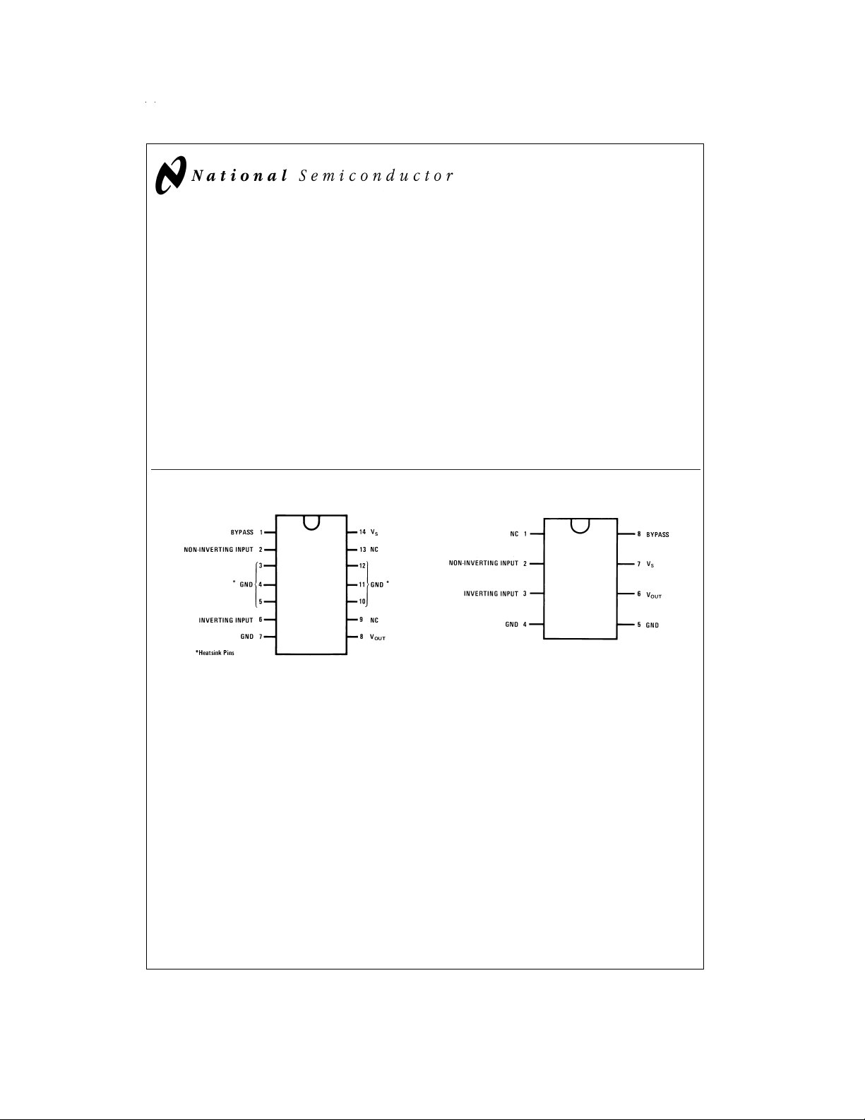
The package outline is standard dual-in-line. A copper lead
frame is used with the center three pins on either side comprising a heat sink. This makes the device easy to use in
standard p-c layout.
Uses include simple phonograph amplifiers, intercoms, line
drivers, teaching machine outputs, alarms, ultrasonic drivers, TV sound systems, AM-FM radio, small servo drivers,
power converters, etc.
Connection Diagrams (Dual-In-Line Packages, Top View)
A selected part for more power on higher supply voltages is
available as the LM384. For more information see AN-69.
Features
n Wide supply voltage range
n Low quiescent power drain
n Voltage gain fixed at 50
n High peak current capability
n Input referenced to GND
n High input impedance
n Low distortion
n Quiescent output voltage is at one-half of the supply
voltage
n Standard dual-in-line package
LM380 Audio Power Amplifier
December 1994
DS006977-2
DS006977-1
Order Number LM380N
See NS Package Number N14A
© 1999 National Semiconductor Corporation DS006977 www.national.com
Order Number LM380N-8
See NS Package Number N08E
Page 2
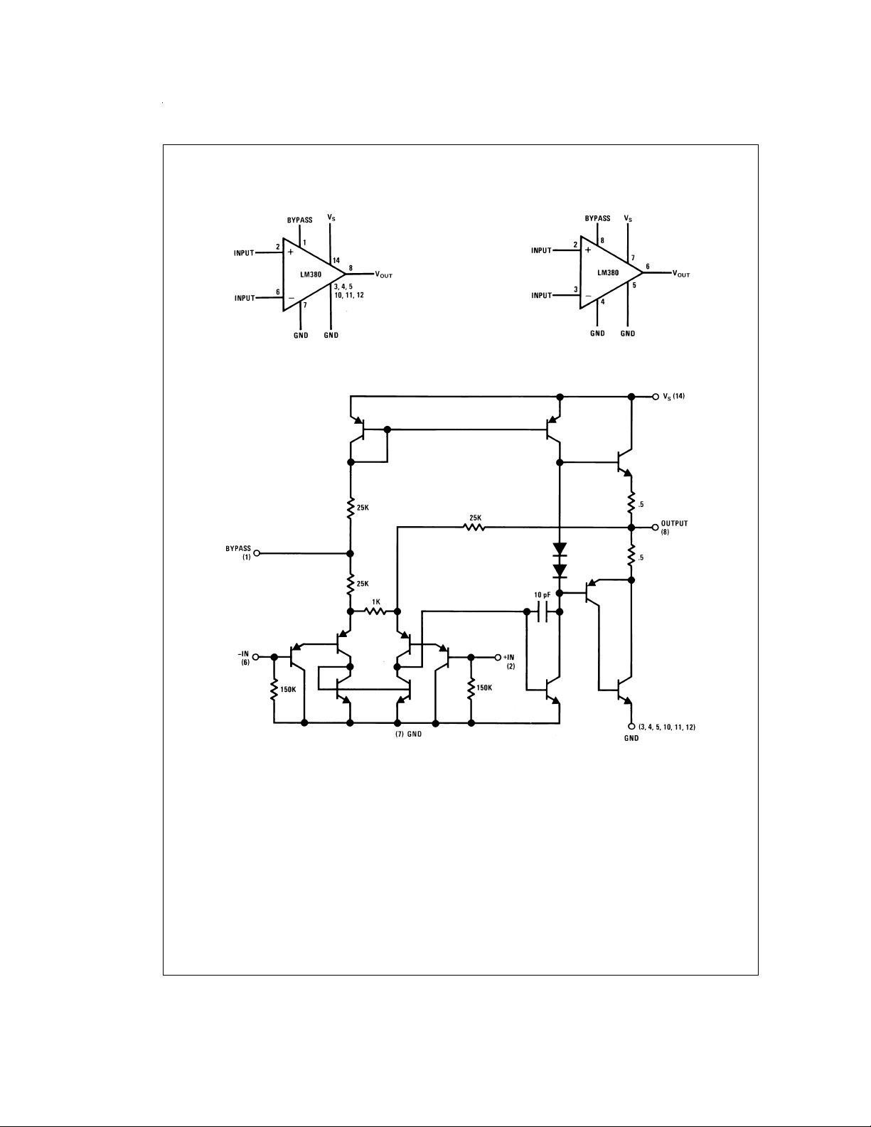
Block and Schematic Diagrams
LM380N
DS006977-3
LM380N-8
DS006977-4
www.national.com 2
DS006977-5
Page 3
Absolute Maximum Ratings (Note 1)
If Military/Aerospace specified devices are required,
please contact the National Semiconductor Sales Office/
Distributors for availability and specifications.
Supply Voltage 22V
Peak Current 1.3A
Package Dissipation 14-Pin DIP (Note 7) 8.3W
Package Dissipation 8-Pin DIP (Note 7) 1.67W
Input Voltage
±
0.5V
Operating Temperature 0˚C to +70˚C
Junction Temperature +150˚C
Lead Temperature (Soldering, 10 sec.) +260˚C
ESD rating to be determined
Thermal Resistance
(14-Pin DIP) 30˚C/W
θ
JC
(8-Pin DIP) 37˚C/W
θ
JC
(14-Pin DIP) 79˚C/W
θ
JA
(8-Pin DIP) 107˚C/W
θ
JA
Storage Temperature −65˚C to +150˚C
Electrical Characteristics (Note 2)
Symbol Parameter Conditions Min Typ Max Units
=
=
8Ω, THD=3%(Notes 4, 5) 2.5 W
L
=
8Ω 14 V
L
5µF.
OUT
=
2W, R
=
8Ω 100k Hz
L
P
OUT(RMS)
A
V
V
OUT
Z
IN
Output Power R
Gain 40 50 60 V/V
Output Voltage Swing R
Input Resistance 150k Ω
THD Total Harmonic Distortion (Notes 5, 6) 0.2
PSRR Power Supply Rejection Ratio (Note 3) 38 dB
V
S
Supply Voltage 10 22 V
BW Bandwidth P
I
Q
V
OUTQ
I
BIAS
I
SC
Note 1: “Absolute Maximum Ratings” indicate limits beyond which damage to the device may occur. Operating Ratings indicate conditions for which the device is
functional, but do not guarantee specific performance limits.
Note 2: V
Note 3: Rejection ratio referred to the output with C
Note 4: With device Pins 3, 4, 5, 10, 11, 12 soldered into a 1/16" epoxy glass board with 2 ounce copper foil with a minimum surface of 6 square inches.
Note 5: C
Note 6: The maximum junction temperature of the LM380 is 150˚C.
Note 7: The package is to be derated at 15˚C/W junction to heat sink pins for 14-pin pkg; 75˚C/W for 8-pin.
Quiescent Supply Current 7 25 mA
Quiescent Output Voltage 8 9.0 10 V
Bias Current Inputs Floating 100 nA
Short Circuit Current 1.3 A
=
S
BYPASS
18V and T
=
25˚C unless otherwise specified.
A
=
0.47 µfd on Pin 1.
BYPASS
p-p
%
www.national.com3
Page 4

Heat Sink Dimensions
Staver Heat Sink#V-7
Staver Company
41 Saxon Ave.
P.O. Drawer H
Bayshore, NY 11706
Tel: (516) 666-8000
Copper Wings
2 Required
Soldered to
Pins 3, 4, 5,
10, 11, 12
Thickness 0.04
Inches
Typical Performance Characteristics
Maximum Device Dissipation vs
Ambient Temperature
Device Dissipation vs Output
Power—4Ω Load
Device Dissipation vs Output
Power—8Ω Load
DS006977-6
DS006977-12
Device Dissipation vs Output
Power—16Ω Load
DS006977-13
www.national.com 4
DS006977-14
DS006977-15
Page 5

Typical Performance Characteristics (Continued)
Power Supply Current vs
Supply Voltage
Total Harmonic Distortion
vs Output Power
DS006977-16
DS006977-19
Total Harmonic Distortion
vs Frequency
Device Dissipation vs
Output Power
DS006977-17
DS006977-20
Output Voltage Gain and
Phase vs Frequency
DS006977-18
Supply Decoupling vs
Frequency
DS006977-21
Typical Applications
Phono Amplifier
DS006977-8
Bridge Amplifier
DS006977-9
www.national.com5
Page 6

Typical Applications (Continued)
Intercom
DS006977-10
Phase Shift Oscillator
www.national.com 6
DS006977-11
Page 7

Physical Dimensions inches (millimeters) unless otherwise noted
Molded Dual-In-Line Package (N)
Order Number LM380N-8
NS Package Number N08E
Molded Dual-In-Line Package (N)
Order Number LM380N
NS Package Number N14A
www.national.com7
Page 8

LM380 Audio Power Amplifier
Notes
LIFE SUPPORT POLICY
NATIONAL’S PRODUCTS ARE NOT AUTHORIZED FOR USE AS CRITICAL COMPONENTS IN LIFE SUPPORT
DEVICES OR SYSTEMS WITHOUT THE EXPRESS WRITTEN APPROVAL OF THE PRESIDENT AND GENERAL
COUNSEL OF NATIONAL SEMICONDUCTOR CORPORATION. As used herein:
1. Life support devices or systems are devices or
systems which, (a) are intended for surgical implant
into the body, or (b) support or sustain life, and
whose failure to perform when properly used in
accordance with instructions for use provided in the
2. A critical component is any component of a life
support device or system whose failure to perform
can be reasonably expected to cause the failure of
the life support device or system, or to affect its
safety or effectiveness.
labeling, can be reasonably expected to result in a
significant injury to the user.
National Semiconductor
Corporation
Americas
Tel: 1-800-272-9959
Fax: 1-800-737-7018
Email: support@nsc.com
www.national.com
National does not assume any responsibility for use of any circuitry described, no circuit patent licenses are implied and National reserves the right at any time without notice to change said circuitry and specifications.
National Semiconductor
Europe
Fax: +49 (0) 1 80-530 85 86
Email: europe.support@nsc.com
Deutsch Tel: +49 (0) 1 80-530 85 85
English Tel: +49 (0) 1 80-532 78 32
Français Tel: +49 (0) 1 80-532 93 58
Italiano Tel: +49 (0) 1 80-534 16 80
National Semiconductor
Asia Pacific Customer
Response Group
Tel: 65-2544466
Fax: 65-2504466
Email: sea.support@nsc.com
National Semiconductor
Japan Ltd.
Tel: 81-3-5639-7560
Fax: 81-3-5639-7507
 Loading...