

Page 1
LM143/LM343 High Voltage
Operational Amplifier
LM143/LM343 High Voltage Operational Amplifier
February 1995
General Description
The LM143 is a general purpose high voltage operational
amplifier featuring operation to
voltage protection up to
ble to those of other super-b op amps. Increased slew rate,
together with higher common-mode and supply rejection,
insure improved performance at high supply voltages. Operating characteristics, in particular supply current, slew rate
and gain, are virtually independent of supply voltage and
temperature. Furthermore, gain is unaffected by output
loading at high supply voltages due to thermal symmetry on
the die. The LM143 is pin compatible with general purpose
op amps and has offset null capability.
Application areas include those of general purpose op
amps, but can be extended to higher voltages and higher
output power when externally boosted. For example, when
used in audio power applications, the LM143 provides a
power bandwidth that covers the entire audio spectrum. In
addition, the LM143 can be reliably operated in environments with large overvoltage spikes on the power supplies,
where other internally-compensated op amps would suffer
catastrophic failure.
The LM343 is similar to the LM143 for applications in less
severe supply voltage and temperature environments.
g
40V, complete input over-
g
40V and input currents compara-
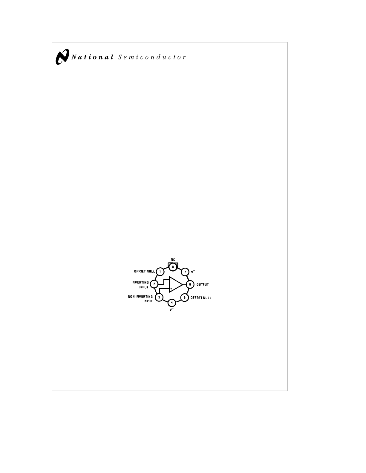
Connection Diagram
Metal Can Package
Top View
Features
Y
Wide supply voltage range
Y
Large output voltage swing
Y
Wide input common-mode range
Y
Input overvoltage protection Fullg40V
Y
Supply current is virtually independent of supply voltage
and temperature
g
4.0V tog40V
Unique Characteristics
Y
Low input bias current 8.0 nA
Y
Low input offset current 1.0 nA
Y
High slew rateÐessentially independent of temperature
and supply voltage 2.5V/ms
Y
High voltage gainÐvirtually independent of resistive
loading, temperature, and supply voltage 100k min
Y
Internally compensated for unity gain
Y
Output short circuit protection
Y
Pin compatible with general purpose op amps
g
37V
g
38V
Order Number LM143H, LM143H/883* or LM343H
TL/H/7783– 1
See NS Package Number H08C
*Available per SMDÝ7800303
C
1995 National Semiconductor Corporation RRD-B30M115/Printed in U. S. A.
TL/H/7783
Page 2
Absolute Maximum Ratings (Note 1)
If Military/Aerospace specified devices are required, please contact the National Semiconductor Sales Office/
Distributors for availability and specifications.
(Note 4)
LM143 LM343
Supply Voltage
g
40V
g
34V
Power Dissipation (Note 1) 680 mW 680 mW
Differential Input Voltage (Note 2) 80V 68V
Input Voltage (Note 2)
Operating Temperature Range
Storage Temperature Range
g
40V
b
55§Ctoa125§C0
b
65§Ctoa150§C
g
34V
Ctoa70§C
§
b
65§Ctoa150§C
Output Short Circuit Duration 5 seconds 5 seconds
Lead Temperature (Soldering, 10 sec.) 300
C 300§C
§
ESD rating to be determined.
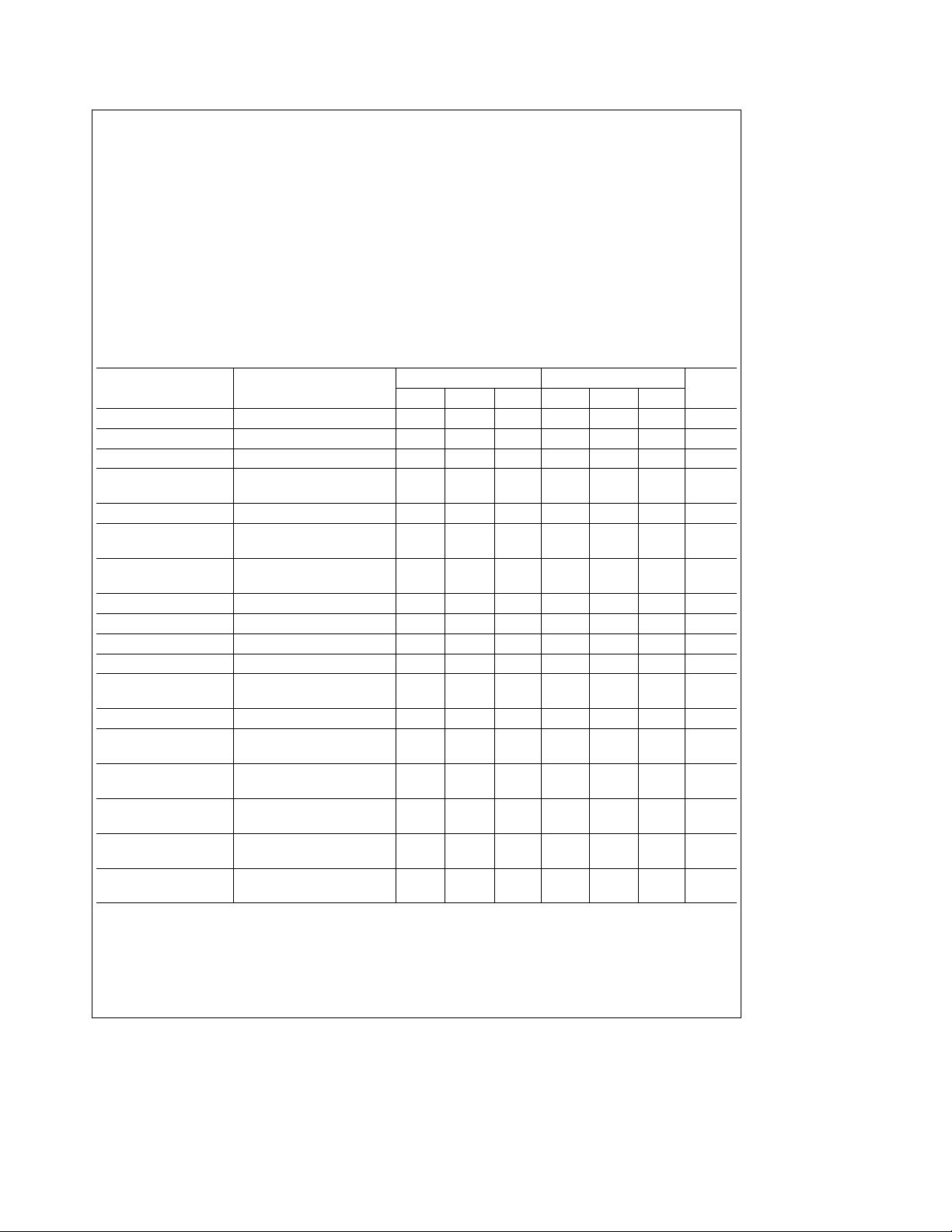
Electrical Characteristics (Note 3)
Parameter Conditions
Input Offset Voltage T
Input Offset Current T
Input Bias Current T
Supply Voltage T
Rejection Ratio
Output Voltage Swing T
Large Signal Voltage T
Gain R
Common-Mode T
Rejection Ratio
Input Voltage Range T
Supply Current (Note 5) T
Short Circuit Current T
Slew Rate T
Power Bandwidth T
Unity Gain Frequency T
Input Offset Voltage T
Input Offset Current T
Input Bias Current T
Large Signal Voltage R
Gain R
Output Voltage Swing R
Note 1: Absolute maximum ratings are not necessarily concurrent, and care must be taken not to exceed the maximum junction temperature of the LM143 (150§C)
or the LM343 (100
ambient, or 20
Note 2: For supply voltage less than
Note 3: These specifications apply for V
0§C.
Note 4: Refer to RETS143X for LM143H and LM1536H military specifications.
Note 5: The maximum supply currents are guaranteed at V
C). For operating at elevated temperatures, devices in the H08 package must be derated based on a thermal resistance of 155§C/W, junction to
§
C/W, junction to case.
§
e
25§C 2.0 5.0 2.0 8.0 mV
A
e
25§C 1.0 3.0 1.0 10 nA
A
e
25§C 8.0 20 8.0 40 nA
A
e
25§C
A
e
A
e
A
t
L
e
A
e
A
e
A
e
A
e
A
e
25§C, V
A
e
R
L
e
A
e
A
e
T
A
e
A
e
T
A
e
A
e
T
A
t
L
t
L
t
L
t
R
L
g
40V for the LM143 and less thang34V for the LM343, the absolute maximum input voltage is equal to the supply voltage.
e
S
t
25§C, R
25§C, V
100 kX
5kX 22 25 20 25 V
L
e
g
10V,
OUT
25§C
25§C
25§C 2.0 4.0 2.0 5.0 mA
25§C2020mA
e
25§C, A
5kX, THDs1%
1 2.5 2.5 V/ms
V
e
40 V
OUT
p-p
,
25§C 1.0M 1.0M Hz
Max 6.0 10
Min 6.0 10
Max 0.8 4.5 0.8 14
Min 1.8 7.0 1.8 14
Max 5.0 35 5.0 55
Min 16 35 16 55
100 kX,T
100 kX,T
5.0 kX,T
5.0 kX,T
g
e
Max 50k 150k 50k 150k
A
e
Min 50k 220k 50k 220k
A
e
Max 22 26 20 26
A
e
Min 22 25 20 25
A
28V. For LM143, T
e
S
e
maxe125§C and T
A
g
40V for the LM143 and V
LM143 LM343
Units
Min Typ Max Min Typ Max
10 100 10 200 mV/V
100k 180k 70k 180k V/V
80 90 70 90 dB
g
g
24
26
g
g
22
26 V
20k 20k Hz
mV
nA
nA
V/V
e
mineb55§C. For LM343, T
A
e
g
34V for the LM343.
S
e
maxe70§C and T
A
e
min
A
V
e
2
Page 3
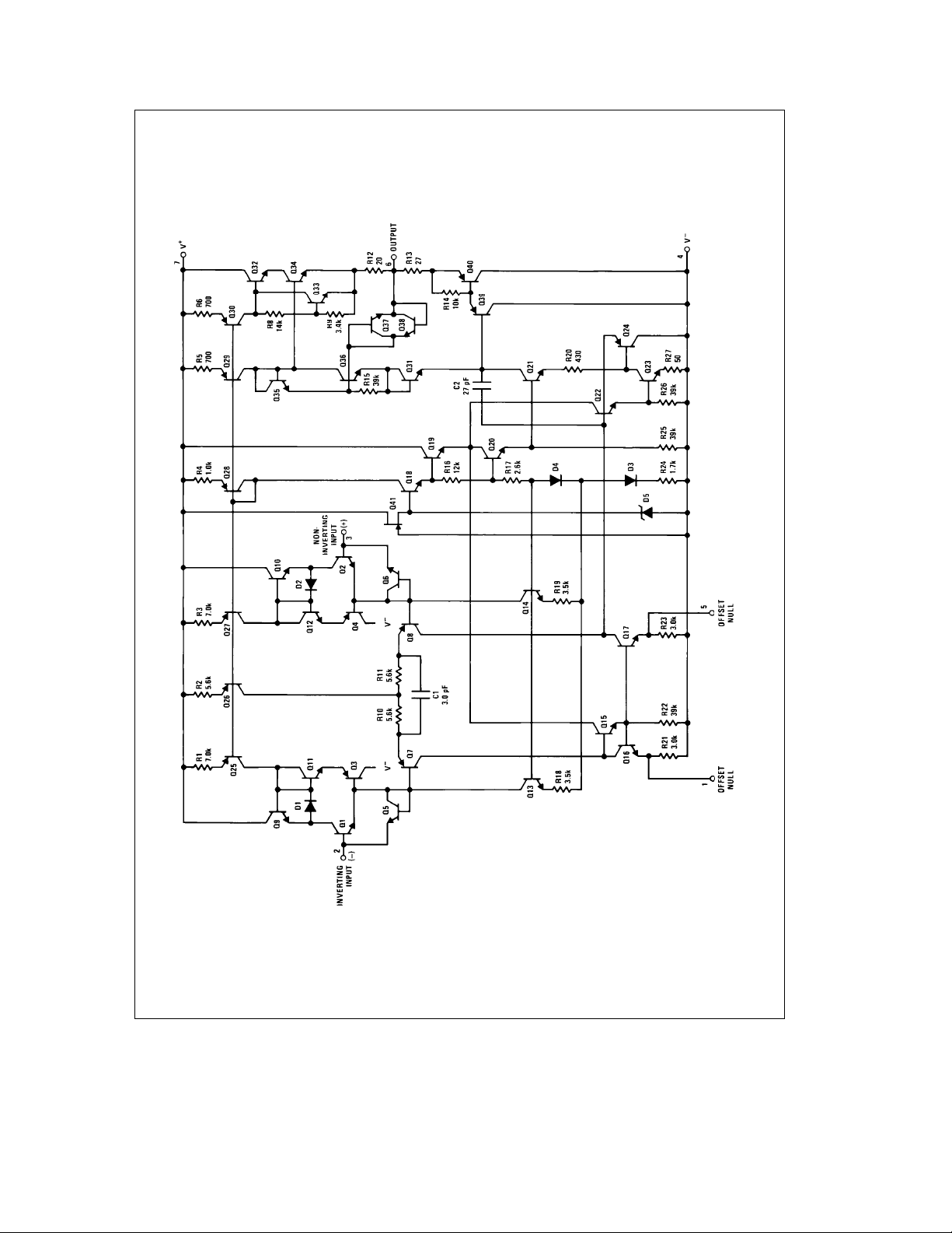
Schematic Diagram
TL/H/7783– 2
3
Page 4
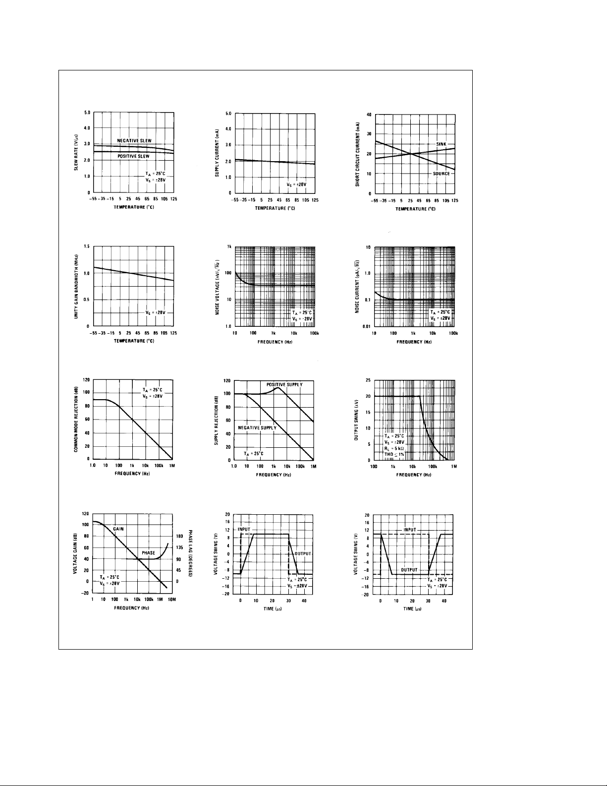
Typical Performance Characteristics
Voltage Follower Slew Rate Supply Current Short Circuit Current
Unity Gain Bandwidth Input Noise Voltage Input Noise Current
Common-Mode Rejection Power Supply Rejection Response
Open Loop Frequency
Response
Voltage Follower Pulse
Response
Large Signal Frequency
Inverter Pulse Response
TL/H/7783– 4
4
Page 5
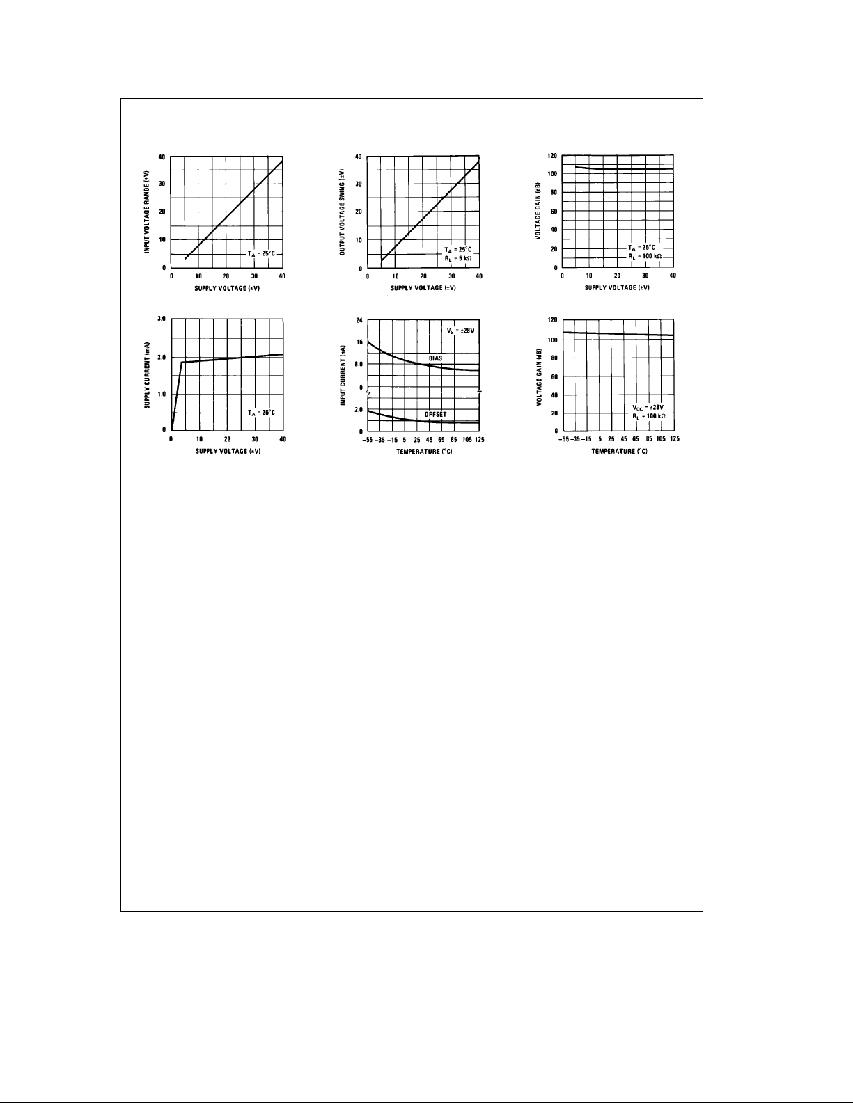
Typical Performance Characteristics (Continued)
Input Voltage Range Output Voltage Swing Voltage Gain
Supply Current Input Current Voltage Gain
Application Hints (See AN-127)
The LM143 is designed for trouble free operation at any
supply voltage up to and including the guaranteed maximum
g
of
40V. Input overvoltage protection, both common-mode
and differential, is 100% tested and guaranteed at the maximum supply voltage. Furthermore, all possible high voltage
destructive modes during supply voltage turn-on have been
eliminated by design. As with most IC op amps, however,
certain precautions should be observed to insure that the
LM143 remains virtually blow-out proof.
Although output short circuits to ground or either supply can
be sustained indefinitely at lower supply voltages, these
short circuits should be of limited duration when operating at
higher supply voltages. Units can be destroyed by any combination of high ambient temperature, high supply voltages,
and high power dissipation which results in excessive die
temperature. This is also true when driving low impedance
or reactive loads or loads that can revert to low impedance;
for example, the LM143 can drive most general purpose op
amps outside of the maximum input voltage range, causing
heavy current to flow and possibly destroying both devices.
Precautions should be taken to insure that the power supplies never become reversed in polarityÐeven under transient conditions. With reverse voltage, the IC will conduct
excessive current, fusing the internal aluminum interconnects. Voltage reversal between the power supplies will almost always result in a destroyed unit.
In high voltage applications which are sensitive to very low
input currents, special precautions should be exercised. For
example, with high source resistances, care should be taken to prevent the magnitude of the PC board leakage currents, although quite small, from approaching those of the
op amp input currents. These leakage currents become
larger at 125
ages. To prevent this, PC boards should be properly
cleaned and coated to prevent contamination and to provide protection from condensed water vapor when operating below 0
cantly reduce leakage currents from the op amp input pins
to the adjacent high voltage pins in the standard op amp pin
connection as shown in
how the guard ring is connected for the three most common
op amp configurations.
Finally, caution should be exercised in high voltage applications as electrical shock hazards are present. Since the
negative supply is connected to the case, users may inadvertantly contact voltages equal to those across the power
supplies.
The LM143 can be used as a plug-in replacement in most
general purpose op amp applications. The circuits presented in the following section emphasize those applications
which take advantage of the unique high voltage abilities of
the LM143.
C and are made worse by high supply volt-
§
C. A guard ring is also recommended to signifi-
§
Figure 1. Figures 2, 3
TL/H/7783– 3
and4show
5
Page 6
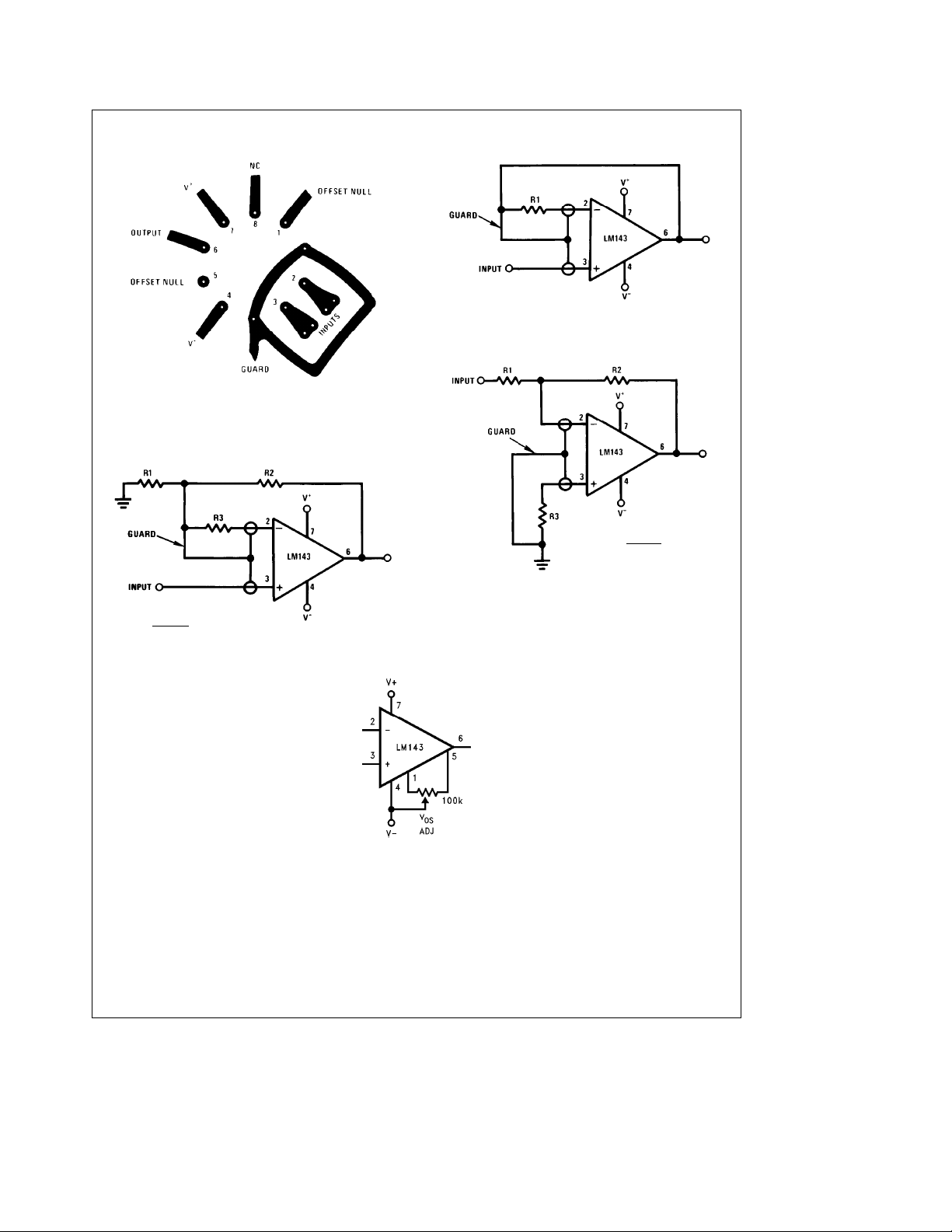
Application Hints (See AN-127) (Continued)
R1eR
SOURCE
FIGURE 2. Guarded Voltage Follower
TL/H/7783– 6
Bottom View
FIGURE 1. Printed Circuit Layout for Input
Guarding with TO-5 Package
R1cR2
R1aR2
e
R
SOURCE
a
R3
FIGURE 3. Guarded Non-Inverting Amplifier
TL/H/7783– 5
TL/H/7783– 7
R1cR2
e
R3
R1aR2
FIGURE 4. Guarded Inverting Amplifier
TL/H/7783– 8
FIGURE 5. Offset Voltage Adjustment
TL/H/7783– 14
6
Page 7
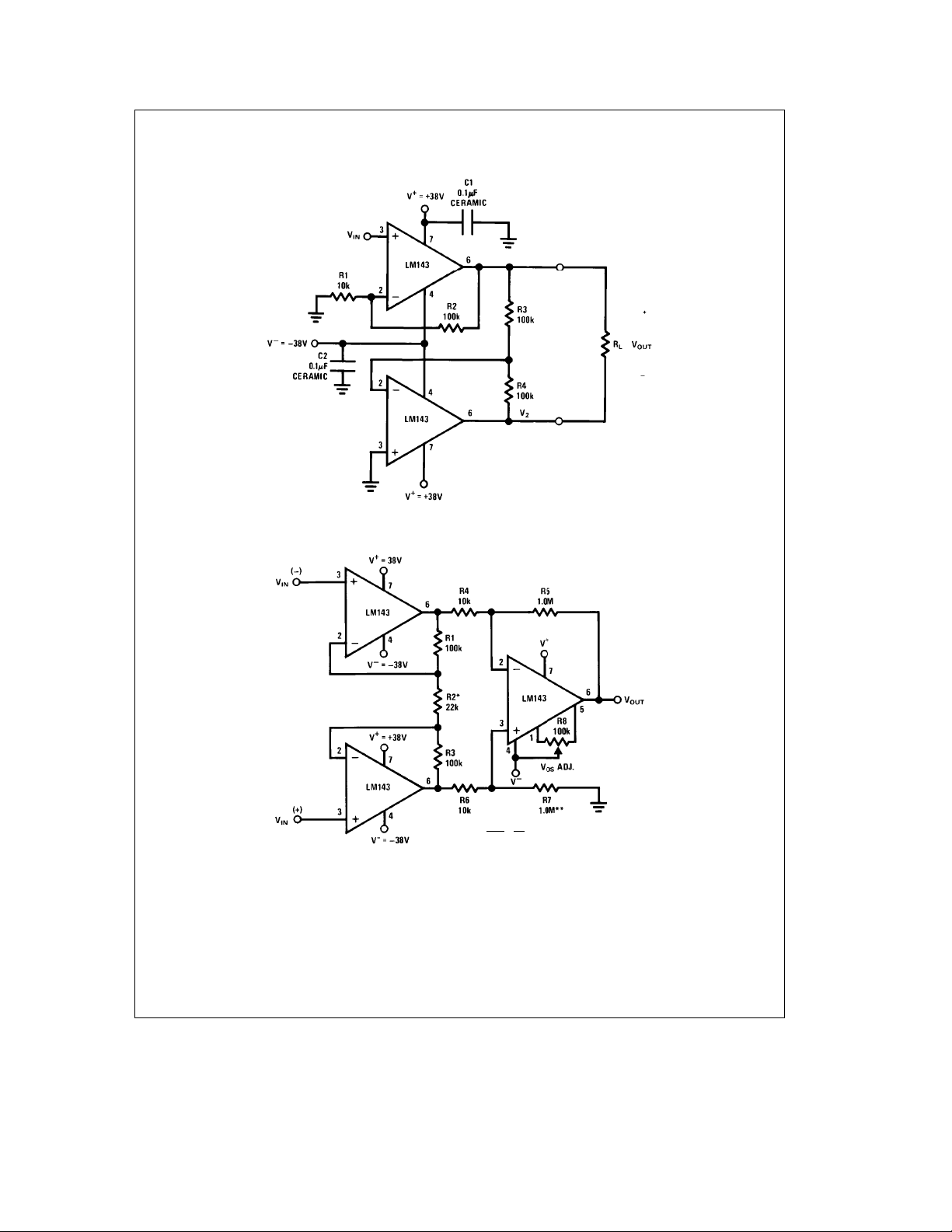
Typical Applications
³
(For more detail see AN-127)
Drive Across a Floating Load
130 V
p-p
g
34V Common-Mode Instrumentation Amplifier
TL/H/7783– 9
2R1
e
a
A
1
V
*R2 may be adjustable to trim the gain.
**R7 may be adjusted to compensate for the resistance tolerance of R4– R7 for best CMR.
³
The 38V supplies allow for a 5% voltage tolerance. All resistors are (/2 watt, except as noted.
R2
#
7
J
R5
R4
WHERE: R4
e
R6
R5eR7
TL/H/7783– 10
Page 8
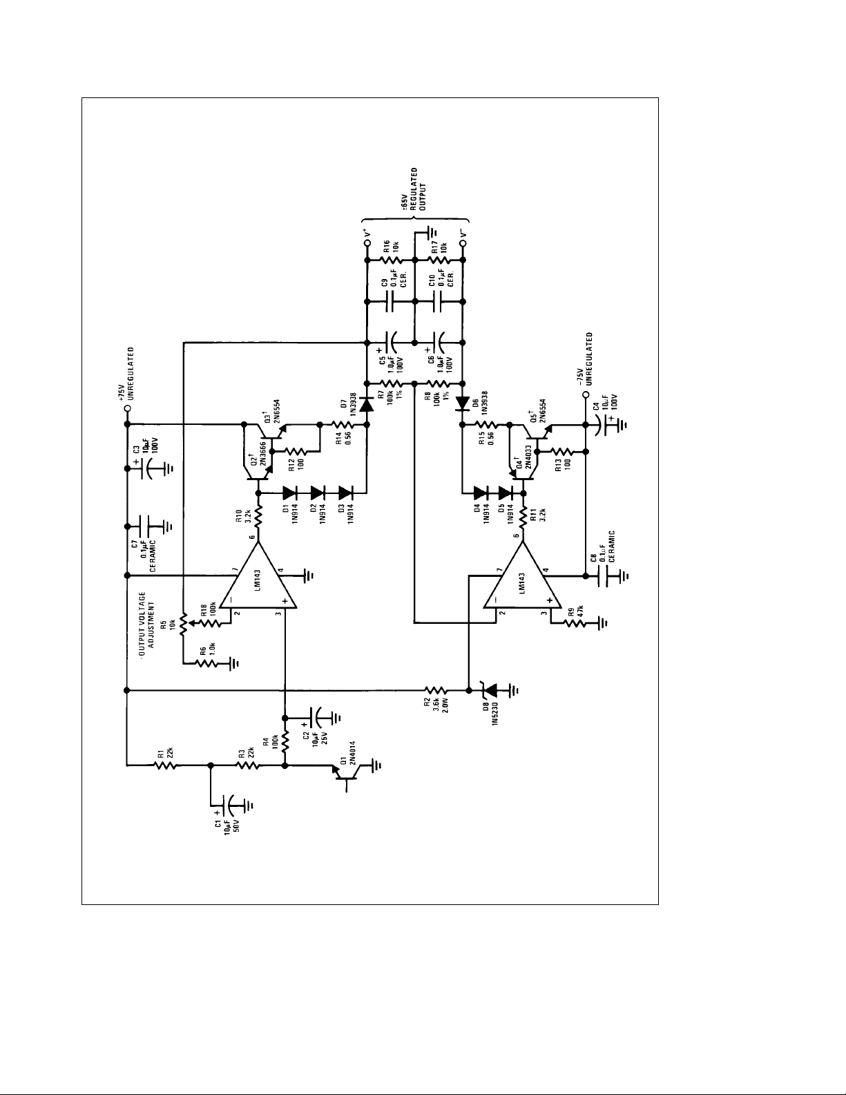
Typical Applications
³
(Continued) (For more detail see AN-127)
TL/H/7783– 11
65V, 1 Amp Power Supply with Short Circuit Protection
g
Tracking
Put on common heat sink.
²
All resistors are (/2 watt, 5%, except as noted.
The 38V supplies allow for a 5% voltage tolerance. All resistors are (/2 watt, except as noted.
³
8
Page 9

Typical Applications
³
(Continued) (For more detail see AN-127)
90W Audio Power Amplifier with Safe Area Protection
²
Put on common heat sink
*34 turns of no. 20 wire on a */8
**Adjust R6 to set I
³
The 38V supplies allow for a 5% voltage tolerance. All resistors are (/2 watt, except as noted.
e
Q
form
×
100 mA TL/H/7783– 12
9
Page 10
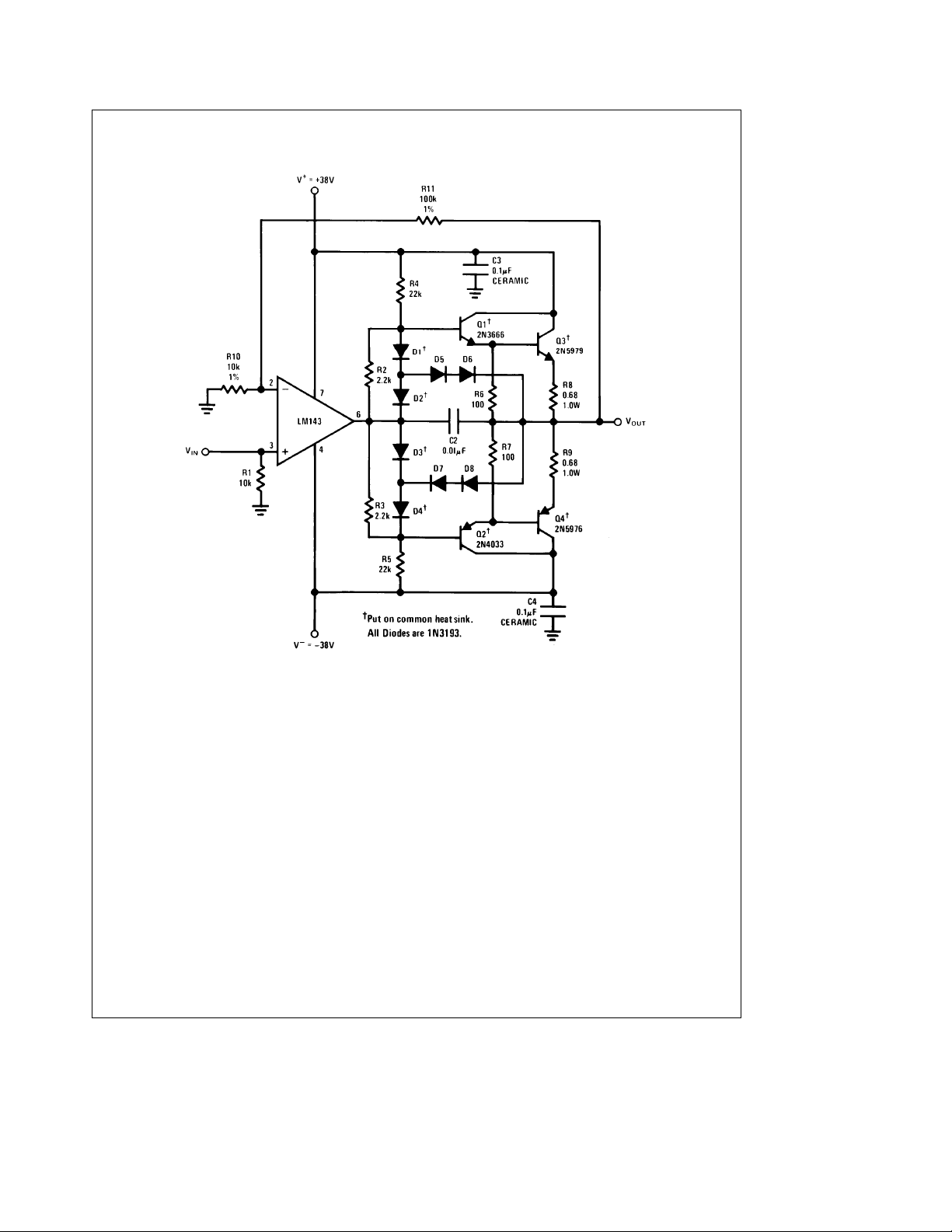
Typical Applications
³
(Continued) (For more detail see AN-127)
1 Amp Power Amplifier with Short Circuit Protection
³
The 38V supplies allow for a 5% voltage tolerance. All resistors are (/2 watt, except as noted.
10
TL/H/7783– 13
Page 11

11
Page 12
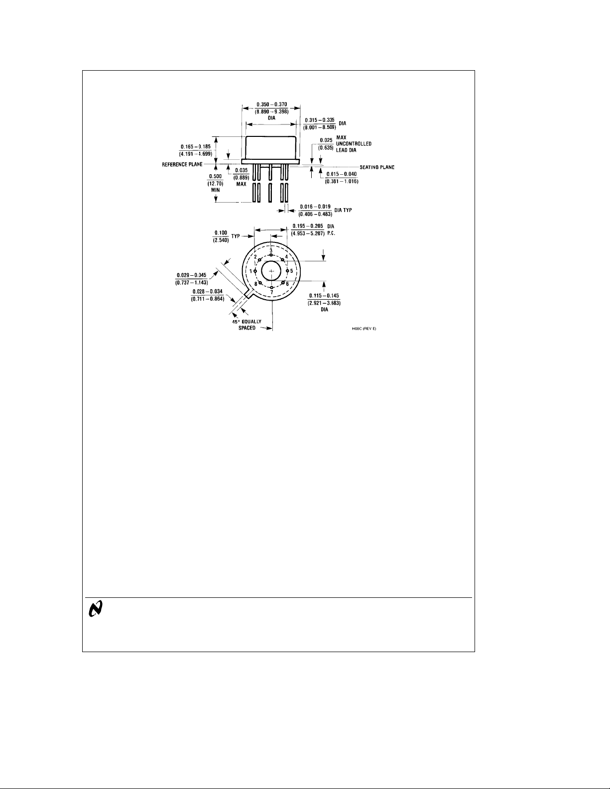
Physical Dimensions inches (millimeters)
Order Number LM143H, LM143H/883 or LM343H
Metal Can Package (H)
NS Package Number H08C
LM143/LM343 High Voltage Operational Amplifier
LIFE SUPPORT POLICY
NATIONAL’S PRODUCTS ARE NOT AUTHORIZED FOR USE AS CRITICAL COMPONENTS IN LIFE SUPPORT
DEVICES OR SYSTEMS WITHOUT THE EXPRESS WRITTEN APPROVAL OF THE PRESIDENT OF NATIONAL
SEMICONDUCTOR CORPORATION. As used herein:
1. Life support devices or systems are devices or 2. A critical component is any component of a life
systems which, (a) are intended for surgical implant support device or system whose failure to perform can
into the body, or (b) support or sustain life, and whose be reasonably expected to cause the failure of the life
failure to perform, when properly used in accordance support device or system, or to affect its safety or
with instructions for use provided in the labeling, can effectiveness.
be reasonably expected to result in a significant injury
to the user.
National Semiconductor National Semiconductor National Semiconductor National Semiconductor
Corporation Europe Hong Kong Ltd. Japan Ltd.
1111 West Bardin Road Fax: (
Arlington, TX 76017 Email: [email protected] Ocean Centre, 5 Canton Rd. Fax: 81-043-299-2408
Tel: 1(800) 272-9959 Deutsch Tel: (
Fax: 1(800) 737-7018 English Tel: (
National does not assume any responsibility for use of any circuitry described, no circuit patent licenses are implied and National reserves the right at any time without notice to change said circuitry and specifications.
Fran3ais Tel: (
Italiano Tel: (
a
49) 0-180-530 85 86 13th Floor, Straight Block, Tel: 81-043-299-2309
a
49) 0-180-530 85 85 Tsimshatsui, Kowloon
a
49) 0-180-532 78 32 Hong Kong
a
49) 0-180-532 93 58 Tel: (852) 2737-1600
a
49) 0-180-534 16 80 Fax: (852) 2736-9960
 Loading...